Table of Contents
Advertisement
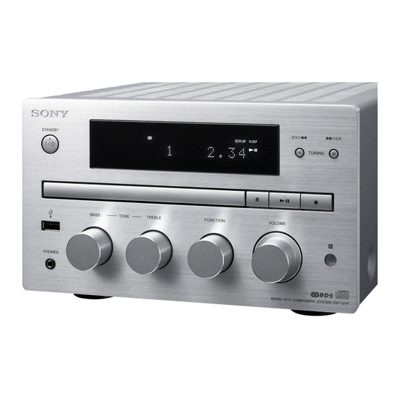
SERVICE MANUAL
Ver. 1.0 2011.06
• CMT-G1BiP/G1iP are composed of following models.
As service manuals are issued for each component model, please
refer to them.
COMPONENT MODEL NAME
Compact disc receiver
Speaker system
SPECIFICATIONS
Power requirements:
AC 230 V, 50/60 Hz
Power consumption: 50 watts
Dimensions (W/H/D) (excl. speakers):
Approx. 220 mm × 133 mm × 335 mm
Mass (excl. speakers): Approx. 5.3 kg
Supplied accessories: Remote Commander (1), R03 (SizeAAA) batteries (2),
AC power cord (1), FM lead antenna (1), AM loop antenna (1), DAB lead
antenna (1) (CMT-G1BiP only), Speaker cords (2) , Speaker pads (8)
Design and specifications are subject to change without notice.
L
Standby power consumption: 0.5 W
9-893-207-01
Sony Corporation
2011F05-1
©
2011.06
Published by Sony Techno Create Corporation
CMT-G1BiP/G1iP
CMT-G1BiP
CMT-G1iP
HCD-G1BiP
HCD-G1iP
SS-CG1
SS-CG1
ACCESSORIES
Ref. No.
Part No.
Description
1-754-102-41
ANTENNA, LOOP (LW.MW) (AM loop antenna)
1-793-184-41
CONNECTOR (F TYPE ADAPTOR)
1-793-184-41
CONNECTOR (F TYPE ADAPTOR)
0
1-837-421-61
CORD SET, POWER-SUPPLY (AC power cord)
0
1-837-426-61
CORD SET, POWER-SUPPLY (AC power cord)
0
1-838-705-61
CORD SET, POWER-SUPPLY (AC power cord)
0
1-839-230-11
CONNECTION CORD WITH SPEAKER
4-283-813-13
MANUAL, INSTRUCTION (ENGLISH) (UK)
4-283-813-23
MANUAL, INSTRUCTION (FRENCH) (AEP)
4-283-813-33
MANUAL, INSTRUCTION (SPANISH) (AEP)
4-283-813-43
MANUAL, INSTRUCTION (GERMAN) (AEP)
4-283-813-53
MANUAL, INSTRUCTION (DUTCH) (AEP)
4-283-813-63
MANUAL, INSTRUCTION (ITALIAN) (AEP)
4-283-813-73
MANUAL, INSTRUCTION (POLISH) (AEP)
4-283-813-92
MANUAL, INSTRUCTION (SIMPLIFIED CHINESE)
4-286-584-01
CUSHION (FOOT) (Speaker pads) (8 pieces, 1 set)
A-1831-638-A
RM-AMU127 (Remote commander)
The components identifi ed by mark 0
or dotted line with mark 0 are critical for
safety.
Replace only with part number specifi ed.
MICRO HI-FI COMPONENT SYSTEM
AEP Model
CMT-G1BiP/G1iP
UK Model
CMT-G1BiP
Chinese Model
CMT-G1iP
Remark
(FM lead antenna)
(DAB lead antenna) (CMT-G1BiP)
(UK)
(AEP)
(Chinese)
(Speaker cords) (2 pieces, 1 set)
(Chinese)
Advertisement
Table of Contents

Related Manuals for Sony CMT-G1BIP


Summary of Contents for Sony CMT-G1BIP
- Page 1 Supplied accessories: Remote Commander (1), R03 (SizeAAA) batteries (2), (DAB lead antenna) (CMT-G1BiP) AC power cord (1), FM lead antenna (1), AM loop antenna (1), DAB lead antenna (1) (CMT-G1BiP only), Speaker cords (2) , Speaker pads (8) 1-837-421-61 CORD SET, POWER-SUPPLY (AC power cord) (UK) Design and specifications are subject to change without notice.
- Page 2 CMT-G1BiP/G1iP REVISION HISTORY Ver. Date Description of Revision 2011.06...
- Page 3 Please note that the use of this accessory with iPod or iPhone may affect wireless performance. COMPACT DISC RECEIVER 9-893-206-01 Sony Corporation 2011F05-1 © 2011.06 Published by Sony Techno Create Corporation...
-
Page 4: Table Of Contents
REPLACE THESE COMPONENTS WITH SONY PARTS WHOSE PART NUMBERS APPEAR AS SHOWN IN THIS MANUAL OR IN SUPPLEMENTS PUBLISHED BY SONY. This appliance is classified as a CLASS 1 LASER product. This marking is located on the rear exterior. -
Page 5: Servicing Notes
HCD-G1BiP/G1iP SECTION 1 SERVICING NOTES MODEL IDENTIFICATION NOTES ON HANDLING THE OPTICAL PICK-UP – Rear Panel – PART No. BLOCK OR BASE UNIT The laser diode in the optical pick-up block may suffer electro- static break-down because of the potential difference generated by the charged electrostatic load, etc. - Page 6 HCD-G1BiP/G1iP HOW TO OPEN THE TRAY WHEN POWER SWITCH TURN OFF lever 1 Insert the hard metal fittings of L character type 6 cm or more in the hole of the chassis. 6 cm or more hole 2 Push the lever in the direction of the arrow A.
- Page 7 HCD-G1BiP/G1iP FL, JOG1, JOG2, USB AND HP BOARD SERVICE POSITION JOG1 board HP board JOG2 board USB board FL board insulating sheet CD MECHANISM DECK SERVICE POSITION MAIN board BD94D board CD mechanism deck (CDM77B-K6BD94D) front panel block MOTOR board...
- Page 8 HCD-G1BiP/G1iP SUB-PT BOARD SERVICE POSITION SUB-PT board MAIN board AMP BOARD SERVICE POSITION AMP board Note: Connect the alligator clips surely with this position. MAIN board CN103 alligator clips lug wire Connect extension jig (Part No. J-2501-212-A) to the AMP board (CN103) and MOTOR board. MOTOR board...
- Page 9 HCD-G1BiP/G1iP DCDC BOARD SERVICE POSITION DCDC board MAIN board TUNER AND DAB BOARD SERVICE POSITION Note: Both the flexible flat cable (9 core) can be connected with the CN406 or CN407 on MAIN board. When you connect the flexible flat cable (9 core) with the CN407 on MAIN board so as not to connect it by TUNER board mistake.
-
Page 10: Disassembly
HCD-G1BiP/G1iP SECTION 2 DISASSEMBLY • This set can be disassembled in the order shown below. 2-1. DISASSEMBLY FLOW 2-2. CASE 2-3. PANEL (CD TRAY) (Page 9) (Page 9) 2-5. PANEL (REAR) BLOCK 2-6. MAIN BOARD 2-4. PANEL (FRONT) BLOCK (Page 12) (Page 11) (Page 10) 2-7. - Page 11 HCD-G1BiP/G1iP Note: Follow the disassembly procedure in the numerical order given. 2-2. CASE 6 case 1 four screws (BV/ring) 2 flat head screw (TP) 5 two claws 2 flat head screw (TP) 2-3. PANEL (CD TRAY) 5 panel (CD tray) Note: There is a possibility of damaged of the panel (CD tray) when the panel (front) block is removed without removing the panel (CD tray).
-
Page 12: Panel (Front) Block
HCD-G1BiP/G1iP 2-4. PANEL (FRONT) BLOCK 8 screw (BVTP3 9 two screws 6 flexible flat cable (17 core) (BV/ring) (CN404) 4 Lift up the coating clip. 5 Turn over the flexible flat cable (15 core). qa panel (front) block 0 claw 8 screw (BVTP3 7 two screws... -
Page 13: Panel (Rear) Block
HCD-G1BiP/G1iP 2-5. PANEL (REAR) BLOCK 5 connector 3 Cut the binding band (taiton). 1 flexible flat cable (CN701) (8 core) (CN408) Note 1: In reassembling, use new binding band (taiton) to fasten the clamp (G1BiP) same as before. ire se i flexible flat cable (9 core) 6 connector (CN4404) -
Page 14: Main Board
HCD-G1BiP/G1iP 2-6. MAIN BOARD Note 1: Refer to page 13 for wire setting. 7 connector (CN701) qs flexible flat cable 6 Cut the binding band (taiton). (8 core) (CN401) Note 2: In reassembling, use new binding band (taiton) to fasten the clamp (G1BiP) same as before. - Page 15 HCD-G1BiP/G1iP SUB-PT board Match the wire to the edge tape of the shield R plate (AMP). Put the wire under the SUB-PT board. 40 mm tape lead pin The wire must not touch the heat-sink. ferrite core rear side The wire must not touch tape R196.
-
Page 16: Holder (Cd Front) Block
HCD-G1BiP/G1iP 2-7. HOLDER (CD FRONT) BLOCK 2 two screws 1 screw (BV3) (BVTP3 3 claw 1 two screws 4 holder (CD front) block (BVTP3 1 screw (BVTP3 3 two claws 2-8. AMP BOARD BLOCK 4 two screw (BV3) 4 screw (BV3) 2 Lift up the lead pin. -
Page 17: Amp Board
HCD-G1BiP/G1iP 2-9. AMP BOARD Note: When you install the flexible flat cable, please install them correctly. There is a possibility that this machine damages flexible flat cable (15 core) when not correctly installing it. 35 mm Insert is straight to the interior. Insert is incline flexible flat flexible flat... -
Page 18: Power Transformer (T901)
HCD-G1BiP/G1iP 2-10. POWER TRANSFORMER (T901) 9 clamp filter (ferrite core) 0 power transformer (T901) 2 connector (CN301) 3 Remove the coating clip from front side the clamp filter (ferrite core). 9 clamp filter (ferrite core) 5 connector (CN952) 8 plate (trans) 1 Lift up the lead pin. -
Page 19: Cd Mechanism Deck Block (Cdm77B-K6Bd94D)
HCD-G1BiP/G1iP 2-11. CD MECHANISM DECK BLOCK (CDM77B-K6BD94D) Note: When you install the flexible flat cable, please install them 2 three screws correctly. There is a possibility that this machine damages (BVTP3 when not correctly installing it. 6 CD mechanism deck block Insert is straight to the interior. -
Page 20: Base Unit (Bu-K6Bd94D)
HCD-G1BiP/G1iP 2-13. BASE UNIT (BU-K6BD94D) 1 floating screw 1 two floating screws (PTPWHM2.6) (PTPWHM2.6) 4 insulator 1 two floating screws (PTPWHM2.6) 2 two cone springs Note: When you install the cone spring, adjust sharp side to 2 two cone springs the floating screw side. -
Page 21: 2-15. Holder (Cd) Block
HCD-G1BiP/G1iP 2-15. HOLDER (CD) BLOCK 5 holder (CD) block Note: Confirm the wire does not rear side hit the edge of holder (CD). lead pin clamp filter 3 Remove the coating clip from (ferrite core) the clamp filter (ferrite core). 1 Lift up the lead pin. -
Page 22: Test Mode
HCD-G1BiP/G1iP SECTION 3 TEST MODE COLD RESET 3. All segments on the fl uorescent indication tube, [STANDBY] The cold reset clears all data including preset data stored in the LED light up. 4. Press the [ TUNING –] button, the model and destina- memory to initial conditions. -
Page 23: Electrical Check
HCD-G1BiP/G1iP SECTION 4 ELECTRICAL CHECK CD SERVICE MODE FM TUNE LEVEL CHECK This mode can run the CD sled motor freely. Use this mode, for instance, when cleaning the optical pick-up. signal generator Procedure: unit 1. Press the [ ] button to turn the power on. 2. - Page 24 HCD-G1BiP/G1iP MEMO...
- Page 49 HCD-G1BiP/G1iP – DAB Board – – MAIN Board – IC4001 MM3291CNRE IC403 PST8429UL GND 1 REGULATOR VDD 1 VOUT GND 2 VREF CE 3 – VDD 2 IC704 BD00GA3WEFJ-E2 IC602 TPS2553DBVR IC705 BD00GC0WEFJ-SE2 RREVERSE VOLTAGE COMPARATOR – CURRENT IN 1 6 OUT SENSE SOFT...
- Page 50 HCD-G1BiP/G1iP IC802 PCM1681PWPR ZR1/ZR1/FMT0 1 SYSTEM CLOCK SYSTEM ZERO MANAGER CLOCK DETECT POWER SUPPLY VOUT1 OUTPUT AMP AND MS/ADR/FMT1 2 CONVERTER LOW-PASS FILTER FUNCTION MC/SCL/DEMP 3 CONTROL MD/SDA/MUTE 4 VOUT2 OUTPUT AMP AND INETERFACE CONVERTER LOW-PASS FILTER VCOM SCK 5 AGND2 OUTPUT AMP AND CONVERTER...
- Page 51 HCD-G1BiP/G1iP – AMP Board – IC101 NJW1159V (TE2) IC102 BA6956AN OUTL 16 GND BOUTL 15 LATCH – 14 CLOCK INTERFACE & 13 DATA LOGIC VDD_OUT 12 CE1 CONTROL LOGIC 11 CE0 OUTR 10 INR BOUTR – VSS_OUT 9 INL LOSC LOSC BIAS V–...
- Page 52 HCD-G1BiP/G1iP – FL Board – IC4101 PT6302LQ-010 VSS 49 OSCI 50 OSCILLATOR OSCO 51 TIMING TIMING RSTB 52 GENERATOR 1 GENERATOR 2 SG35 SG34 DUTY CONTROL GRID SG33 CSB 53 8 BIT DRIVER SG32 CLKB 54 SHIFT DIGIT CONTROL REGISTER SG31 DIN 55 SG30...
- Page 53 HCD-G1BiP/G1iP • IC Pin Function Description BD94D BOARD IC101 TC94A70FG-101 (CD-MP3 PROCESSOR) Pin No. Pin Name Description AVSS3 Ground terminal RFZI RF ripple zero crossing signal input terminal RFRP RF ripple signal output terminal SBAD Sub beam addition signal output terminal Not used Focus error signal output terminal Not used...
- Page 54 HCD-G1BiP/G1iP Pin No. Pin Name Description Micro controller interface mode selection signal input terminal Fixed at “H” in this unit DOUT Digital audio data output terminal Not used AOUT1 Audio data output to the DSP BCKO Bit clock signal output to the DSP LRCKO L/R sampling clock signal output to the DSP Digital audio data input terminal...
- Page 55 HCD-G1BiP/G1iP MAIN BOARD IC402 R5F3650KBDFA (SYSTEM CONTROLLER) Pin No. Pin Name Description DP SDA/SPI DOUT Serial data output to the fl uorescent indicator tube driver DP SCL Serial data transfer clock signal output to the fl uorescent indicator tube driver DP CS Chip select signal output to the fl...
- Page 56 HCD-G1BiP/G1iP Pin No. Pin Name Description HP DET Headphone plug insert detection signal input terminal “H”: headphone plug is inserted HP MUTE Headphone muting on/off control signal output terminal “L”: muting on CDM OUT SW Disc tray open position detection switch input terminal “L”: disc tray is opened CDM IN SW Disc tray close position detection switch input terminal...
- Page 57 HCD-G1BiP/G1iP MAIN BOARD IC601 BU94604KV-E2 (USB DRIVER) Pin No. Pin Name Description RESETX Reset signal input from the system controller “L”: reset SEL_SLAVE Mode setting terminal “L”: slave, “H”: stand alone Fixed at “L” in this unit Mode setting terminal “L”: MP1, MP2 and MP3 play, “H”: MP3 play only SEL_MP3 Fixed at “L”...
- Page 58 HCD-G1BiP/G1iP MAIN BOARD IC805 BU9408KS2 (DSP) Pin No. Pin Name Description DVDDPLL Power supply terminal (+3.3V) FILT1 Filter connection terminal for the PLL DGNDPLL Ground terminal FILT2 Filter connection terminal for the PLL SCANTEST Digital test signal input terminal Not used I2CADR IIC slave address selection terminal Not used...
-
Page 59: Exploded Views
HCD-G1BiP/G1iP SECTION 6 EXPLODED VIEWS Note: • -XX and -X mean standardized parts, so • The mechanical parts with no reference The components identifi ed by mark 0 they may have some difference from the number in the exploded views are not sup- or dotted line with mark 0 are critical for original one. -
Page 60: Front Panel Section
HCD-G1BiP/G1iP 6-2. FRONT PANEL SECTION not supplied (FL board) not supplied ND4101 not supplied not supplied (JOG2 board) S4322 S4321 S4301 not supplied (JOG1 board) included in S4322 included in S4321 included in S4301 Ref. No. Part No. Description Remark Ref. -
Page 61: Rear Panel Section
HCD-G1BiP/G1iP 6-3. REAR PANEL SECTION not supplied not supplied (G1BiP) not supplied (G1BiP) DAB1 not supplied CN01 F4401 108 108 not supplied (DAB board) not supplied not supplied not supplied not supplied not supplied (SUB-PT board) MAIN board section Ref. No. Part No. -
Page 62: Main Board Section
HCD-G1BiP/G1iP 6-4. MAIN BOARD SECTION not supplied supplied not supplied not supplied not supplied supplied not supplied not supplied F303 F304 not supplied not supplied not supplied chassis section Ref. No. Part No. Description Remark Ref. No. Part No. Description Remark 3-077-331-21 +BV3 (3-CR) -
Page 63: Chassis Section
HCD-G1BiP/G1iP 6-5. CHASSIS SECTION T901 CD mechanism deck section (CDM77B-K6BD94D) supplied F951 not supplied not supplied not supplied not supplied Ref. No. Part No. Description Remark Ref. No. Part No. Description Remark 4-275-208-01 CUSHION (FOOT) 1-839-493-21 CABLE, FLEXIBLE FLAT (21 CORE) 0 F951 4-275-207-01 FOOT... -
Page 64: Cd Mechanism Deck Section (Cdm77B-K6Bd94D)
HCD-G1BiP/G1iP 6-6. CD MECHANISM DECK SECTION (CDM77B-K6BD94D) not supplied not supplied (MOTOR board) not supplied (including sled motor, spindle motor) spindle motor sled motor S201 Ref. No. Part No. Description Remark Ref. No. Part No. Description Remark 0 256 A-1242-967-B LOADING (BK) ASSY (Including MOTOR board) A-4735-357-A BASE ASSY, OP (KSM-213D) -
Page 65: Electrical Parts List
HCD-G1BiP/G1iP SECTION 7 ELECTRICAL PARTS LIST Note: • Due to standardization, replacements in • CAPACITORS When indicating parts by reference num- uF: µF the parts list may be different from the ber, please include the board name. parts specifi ed in the diagrams or the com- •... - Page 66 HCD-G1BiP/G1iP Ref. No. Part No. Description Remark Ref. No. Part No. Description Remark C1102 1-162-962-11 CERAMIC CHIP 470PF D002 6-503-020-01 DIODE DZ2J082M0L C1103 1-124-917-11 ELECT 33uF D003 6-503-020-01 DIODE DZ2J082M0L C1104 1-162-966-11 CERAMIC CHIP 0.0022uF D004 8-719-081-97 DIODE MMDL914T1 C1105 1-162-966-11 CERAMIC CHIP 0.0022uF D105...
- Page 67 HCD-G1BiP/G1iP Ref. No. Part No. Description Remark Ref. No. Part No. Description Remark < COIL > R178 1-216-864-11 SHORT CHIP R179 1-216-793-11 METAL CHIP 1/10W L1101 1-456-412-11 COIL, CHOKE 10uH R180 1-216-793-11 METAL CHIP 1/10W L1102 1-456-412-11 COIL, CHOKE 10uH R181 1-216-793-11 METAL CHIP...
- Page 68 HCD-G1BiP/G1iP BD94D Ref. No. Part No. Description Remark Ref. No. Part No. Description Remark R2126 1-249-186-31 CARBON 1/3W C205 1-107-826-11 CERAMIC CHIP 0.1uF R2127 1-216-864-11 SHORT CHIP C206 1-165-908-11 CERAMIC CHIP 1uF R2128 1-249-489-11 CARBON 1/2W C207 1-165-908-11 CERAMIC CHIP 1uF R2129 1-260-105-41 CARBON...
- Page 69 HCD-G1BiP/G1iP BD94D DCDC Ref. No. Part No. Description Remark Ref. No. Part No. Description Remark R204 1-216-864-11 SHORT CHIP < IC > R205 1-216-809-11 METAL CHIP 1/10W IC4001 6-711-132-01 IC MM3291CNRE R210 1-216-809-11 METAL CHIP 1/10W R211 1-216-809-11 METAL CHIP 1/10W <...
- Page 70 HCD-G1BiP/G1iP DCDC Ref. No. Part No. Description Remark Ref. No. Part No. Description Remark C983 1-126-926-11 ELECT 1000uF R968 1-218-827-11 METAL CHIP 0.5% 1/10W C987 1-114-503-21 CERAMIC CHIP 10uF R969 1-218-867-11 METAL CHIP 6.8K 0.5% 1/10W C988 1-114-503-21 CERAMIC CHIP 10uF R970 1-211-989-11 METAL CHIP...
- Page 71 HCD-G1BiP/G1iP JOG1 JOG2 Ref. No. Part No. Description Remark Ref. No. Part No. Description Remark < JUMPER RESISTOR > C4203 1-107-826-11 CERAMIC CHIP 0.1uF JR4115 1-216-864-11 SHORT CHIP < DIODE > JR4116 1-216-864-11 SHORT CHIP D4201 6-500-848-01 DIODE MC2840-T112-1 < COIL > <...
- Page 72 HCD-G1BiP/G1iP JOG2 MAIN Ref. No. Part No. Description Remark Ref. No. Part No. Description Remark R4328 1-216-829-11 METAL CHIP 4.7K 1/10W C807 1-124-779-00 ELECT CHIP 10uF C808 1-124-779-00 ELECT CHIP 10uF < ROTARY ENCODER > C809 1-124-779-00 ELECT CHIP 10uF C810 1-165-989-11 CERAMIC CHIP 10uF...
- Page 73 HCD-G1BiP/G1iP MAIN Ref. No. Part No. Description Remark Ref. No. Part No. Description Remark C1408 1-164-854-11 CERAMIC CHIP 15PF CN701 1-764-250-21 PIN, CONNECTOR (PC BOARD) 4P C1409 1-164-870-11 CERAMIC CHIP 68PF CN702 1-816-296-21 PIN, CONNECTOR (PC BOARD) 9P C1410 1-164-940-11 CERAMIC CHIP 0.0033uF CN803 1-794-032-21...
- Page 74 HCD-G1BiP/G1iP MAIN Ref. No. Part No. Description Remark Ref. No. Part No. Description Remark Q813 8-729-043-90 TRANSISTOR IMX9T110 R471 1-218-941-81 METAL CHIP 1/16W Q814 8-729-027-46 TRANSISTOR DTC114YKA-T146 R472 1-218-941-81 METAL CHIP 1/16W < RESISTOR > R473 1-218-941-81 METAL CHIP 1/16W R474 1-218-941-81 METAL CHIP...
- Page 75 HCD-G1BiP/G1iP MAIN Ref. No. Part No. Description Remark Ref. No. Part No. Description Remark R534 1-218-990-81 SHORT CHIP R597 1-218-990-81 SHORT CHIP 0 (G1BiP) R600 1-218-965-11 METAL CHIP 1/16W R535 1-218-990-81 SHORT CHIP R601 1-218-941-81 METAL CHIP 1/16W R536 1-218-981-91 METAL CHIP 220K 1/16W...
- Page 76 HCD-G1BiP/G1iP MAIN Ref. No. Part No. Description Remark Ref. No. Part No. Description Remark R746 1-208-713-11 METAL CHIP 0.5% 1/16W R876 1-218-959-11 METAL CHIP 3.3K 1/16W R747 1-218-990-81 SHORT CHIP R877 1-216-836-11 METAL CHIP 1/10W R752 1-216-864-11 SHORT CHIP R878 1-218-990-81 SHORT CHIP R879...
- Page 77 HCD-G1BiP/G1iP MAIN MOTOR SUB-PT TUNER Ref. No. Part No. Description Remark Ref. No. Part No. Description Remark R1421 1-218-990-81 SHORT CHIP D4406 6-502-961-01 DIODE DA2J10100L R1428 1-208-709-11 METAL CHIP 0.5% 1/16W R1429 1-208-709-11 METAL CHIP 0.5% 1/16W < FUSE > R1433 1-218-990-81 SHORT CHIP...
- Page 78 HCD-G1BiP/G1iP TUNER Ref. No. Part No. Description Remark Ref. No. Part No. Description Remark < JUMPER RESISTOR > 1-457-413-11 CORE, FERRITE 0 112 1-697-045-11 AC INLET (2P) JR502 1-216-864-11 SHORT CHIP 1-832-585-21 CABLE, FLEXIBLE FLAT (15 CORE) 1-457-413-11 CORE, FERRITE <...
- Page 79 HCD-G1BiP/G1iP MEMO...
- Page 80 HCD-G1BiP/G1iP REVISION HISTORY Checking the version allows you to jump to the revised page. Also, clicking the version at the top of the revised page allows you to jump to the next revised page. Ver. Date Description of Revision 2011.06...