
Related Manuals for Siemens CCDA1415-DN


Summary of Contents for Siemens CCDA1415-DN
-
Page 1: Instruction Manual
CCDA1415-DN DAY/NIGHT Dome System Instruction Manual Fire & Security Products Siemens Building Technologies... - Page 2 Data and design subject to change without notice. / Supply subject to availability. © 2004 Copyright by Siemens Building Technologies AG Wir behalten uns alle Rechte an diesem Dokument und an dem in ihm dargestellten Gegenstand vor. Der Empfänger anerkennt diese Rechte und wird dieses Dokument nicht ohne unsere vorgängige schriftliche Ermächtigung ganz oder teilweise Dritten zugänglich machen...
- Page 3 SensorNet 485 networks require 22 AWG unshielded cable. Do not exceed 32 devices per cable run. Siemens RS422/RS485 networks require 22 AWG shielded cable. Do not exceed 10 devices per cable run. Always terminate the camera dome connected at the end of a RS422/RS485 cable run using termination jumpers.
-
Page 4: Warnings And Cautions
All the obligations of Siemens are detailed in the relevant sales contract which also contains the complete and solely applicable warranty clause. These contractual warranty conditions are neither extended nor restricted by the information contained within this document. -
Page 5: Table Of Contents
Working with AGC and Open Shutter Settings ........104 9.5.1 Understanding How Advanced Shutter Settings Improve Low-Light Performance..................105 9.5.2 The Relationship between IR Mode and AGC and Open Shutter Settings................106 9.5.3 Configuring AGC and Open Shutter Settings ........106 Siemens Building Technologies BE_CCDA1415-DN.doc Fire & Security Products 05.2004... - Page 6 Setting and Enabling the Dome Password ...........134 12.3.1 Setting or Changing the Dome Password..........134 12.3.2 Enabling or Disabling Password Protection ..........134 Displaying Dome Information ............135 13.1 Understanding the Dome Information Screen........135 13.2 Viewing Dome Operating Statistics............136 Siemens Building Technologies BE_CCDA1415-DN.doc Fire & Security Products 05.2004...
-
Page 7: General Details
EN 61000-4-3 EN 61000-4-4 EN 61000-4-5 EN 61000-4-6 The EU conformity certificate which is available for the associated authorities is held at: Siemens Building Technologies Fire & Security Products GmbH & Co. oHG Siemensallee 84 76187 Karlsruhe Siemens Building Technologies BE_CCDA1415-DN.doc Fire &... -
Page 8: Ordering Data
Wall bracket, indoor 2GF1191-8BL for dome camera CCDA1415-DN 1.85 Wall mount bracket, short 2GF1191-8BM for dome cameras CCDA1415-DN with outdoor housing and CCDA1410-WD Wall mount bracket, long 2GF1191-8BN for dome cameras CCDA1415-DN with outdoor housing and CCDA1410-WD Outdoor pendant mount... -
Page 9: Scope Of Delivery
Scope of Delivery Scope of Delivery Instruction Manual Dome Camera CCDA1415-DN Ceiling Mount incl. Mounting Base Screws (subpackage) Safety Lanyard Tools Required Slotted screwdriver Siemens Building Technologies BE_CCDA1415-DN.doc Fire & Security Products 05.2004... -
Page 10: Technical Data
2000 Vrms PTC resettable fuse protects transformer, TVS RATED AT 5.6 V, 40 A, 0.1 joules; 10 kA impulse rated gas tube Siemens RS422/RS485 Interface Series resistor of 33 Ohm; TVS rated at 5.6 V, 40 A, 0.1 joules Alarm Input Series resistor of 33 Ohm;... - Page 11 82.8 mm 2.5° (H) x 1.9° (V) (equivalent to 8 to 80 mm 1/2-inch CCD or 11 to 110 mm on 2/3-inch CCD Dimensions (D x H) 120 x 205 mm Siemens Building Technologies BE_CCDA1415-DN.doc Fire & Security Products 05.2004...
-
Page 12: About The Dome Camera
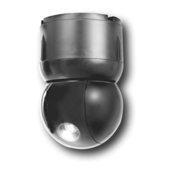
The SIEMENS DAY/NIGHT Dome System CCDA1415-DN comes in black finish, mounts indoors or outdoors, and can communicate with the video controller over Siemens RS422/RS485 network. The dome consists of a mounting base, and a housing and rotating eyeball assembly. Mounting Base The housing and eyeball assembly connects to the base using a twist and lock action, enabling it to be moved easily from one location to another. -
Page 13: Indoor Ceiling Mounting
(Fig. 2), or to tile ceiling T-bars where they intersect (Fig. 3). Fig. 2 Surface mounting to hard Fig. 3 Surface mounting to tile ceilings ceilings Siemens Building Technologies BE_CCDA1415-DN.doc Fire & Security Products 05.2004... -
Page 14: Indoor Ceiling/Wall Mounting (Optional)
2 foot grids. The bracket distributes the weight of the dome and the Top Hat housing across the T-bar framework of the ceiling. Fig. 4 Indoor mounting structures (optional) Siemens Building Technologies BE_CCDA1415-DN.doc Fire & Security Products 05.2004... -
Page 15: Outdoor Mounting (Optional)
NOTE: Do not use the I/O board (designed for indoor use) in place of the environmental board. Fig. 5 Outdoor housing (optional) Siemens Building Technologies BE_CCDA1415-DN.doc Fire & Security Products 05.2004... -
Page 16: Outdoor Mounting Structures (Optional)
About the Dome Camera Outdoor Mounting Structures (Optional) Fig. 6 Outdoor brackets (optional) Data Cable Requirements Table 1 shows the data cable requirements for Siemens RS422/RS485 and SensorNet RS485 networks. SensorNet RS485 Siemens RS422/RS485 Cable type 1 unshielded, twisted pair... -
Page 17: Indoor Installation
Set switches from most significant bit (MSB) to least significant bit (LSB). For example: For address 066, set SW3 to 0, SW2 to 6, and SW1 to 6. Fig. 7 Setting the address switches Siemens Building Technologies BE_CCDA1415-DN.doc Fire & Security Products 05.2004... - Page 18 In some cases, an additional termination of the RS422/RS485 buses may be required. NOTE: You may need a small slotted screwdriver to gently pry jumper loose. Be careful not to damage underlying PC board. Siemens Building Technologies BE_CCDA1415-DN.doc Fire & Security Products 05.2004...
- Page 19 RS422 Data In Low (–) RS422 Data Out High (+) to the next dome RS422 Data Out Low (–) The following interface parameters are applicable for the Siemens protocol RS422/RS485: Data rate in baud 19,200 bits/s Start bit...
-
Page 20: Alarm Connections
Insert plug into mating receptacle in top of housing and eyeball assembly. – Alarm connections Designation +12 V DC Alarm Out Alarm In Common 9-pin plug 4-pin plug Fig. 10 Cable connections Siemens Building Technologies BE_CCDA1415-DN.doc Fire & Security Products 05.2004... -
Page 21: Connecting To A Mounting Base With I/O Board
Set data communications jumper JW1. If data lines continue to another dome, set JW1 across pins 1-2 (un-terminated). Otherwise, set JW1 across pins 2-3 (terminated). Connect video cable to BNC connector P8 on I/O board. Connect Siemens RS422/RS485, or SensorNet 485 data wires to connector P1. Siemens Building Technologies BE_CCDA1415-DN.doc Fire &... - Page 22 RS422 Data Out Low (–) must be connected using a jumper cable! IMPORTANT If the Siemens protocol is used, the SensorNet input must be jumpered! The following interface parameters are applicable for the Siemens protocol RS422/RS485: Data rate in baud...
- Page 23 Alarm 2 input (3.5 mA sink) Alarm 1 input (3.5 mA sink) Alarm 0 input (3.5 mA sink) Ground Ground Connect power to P7 connector. Designation 24 V AC Ground 24 V AC Siemens Building Technologies BE_CCDA1415-DN.doc Fire & Security Products 05.2004...
- Page 24 L A T C H Fig. 14 Connecting the housing and eyeball assembly to the base Siemens Building Technologies BE_CCDA1415-DN.doc Fire & Security Products 05.2004...
-
Page 25: Using The Dome Configuration Utility
If the dome is installed together with the Siemens Control Unit CKA3210 or CKA4810, press and hold Cam, then press F1. The Dome Configuration Utility provides a means to setting features for your camera dome via a text overlay menu. -
Page 26: Working With The Dome Configuration Utility
Once the Dome Configuration Menu is displayed, you may select a menu item, and then modify the settings you want to change. The following table summarizes the controller commands for Siemens Control Unit CKA3210 and CKA4810. For combination keystrokes, press and hold each button in sequence, then release. -
Page 27: Restoring Factory Settings
If you do not want to start the configuration utility, select Cancel to return to normal dome operation. IMPORTANT If you forget the password, contact your Siemens Representative for assistance. Restoring Factory Settings Some screens provide a choice to restore factory settings. This choice applies only to those settings currently displayed on the screen. -
Page 28: Configuring Pan, Tilt, Zoom, And Synchronization Options
Change the setting. Select On to enable the flip feature. – Select Off to disable the flip feature. – The default setting is Off. Select Exit. The Dome Configuration Menu appears. Siemens Building Technologies BE_CCDA1415-DN.doc Fire & Security Products 05.2004... -
Page 29: Adjusting The Zoom Stop Settings
Configuring Pan, Tilt, Zoom, and Synchronization Options Adjusting the Zoom Stop Settings The SIEMENS DAY/NIGHT Dome CCDA1415-DN includes a 23 x optical zoom camera with 8 x digital zoom capability. The maximum possible zoom is 184 x. Zoom stop settings define how the zoom function is partitioned. Depending on the current zoom level, the camera will either stop at the first zoom stop setting or continue to the maximum zoom setting. -
Page 30: Changing The Line Lock Setting
If you want to reinitialize the dome, select Yes. Changes to the Line Lock – setting will take effect when the dome finishes the reset. Select Exit. The Dome Configuration Menu appears. Siemens Building Technologies BE_CCDA1415-DN.doc Fire & Security Products 05.2004... -
Page 31: Configuring Camera Features
To change settings, move the highlight bar to the appropriate field and make the changes. To change the settings for this screen to the factory defaults, select Reset to Factory Settings. To return to the Dome Configuration Menu, select Exit. Siemens Building Technologies BE_CCDA1415-DN.doc Fire & Security Products 05.2004... -
Page 32: Adjusting White Balance Settings
(purple). As the values for both the red and blue settings are decreased, the image appears more green. Tip: Auto White Bal must be set to Off to manually change the Red and Blue settings. Siemens Building Technologies BE_CCDA1415-DN.doc Fire & Security Products 05.2004... -
Page 33: Changing Automatic White Balance Settings
Select Exit. The Dome Configuration Menu appears. Understanding How IR Mode (Black & White) Operates SIEMENS DAY/NIGHT Dome CCDA1415-DN provides a black-and-white (B/W) mode to improve camera performance when the light level falls below certain thresholds. This allows clear images to be obtained under low-light conditions. This is referred to as IR Mode. -
Page 34: Manually Activating Or Deactivating The Ir Mode
This allows you to change between color and B/W modes as needed. To change the mode using Siemens RS422/RS485 protocols: press and hold Cam-button on keyboard, press and hold button F3. Using the manual command has the following affect on the menu settings: If the current IR Mode setting is... -
Page 35: Understanding Wide Dynamic Range
However, this causes the outdoor scene to appear too bright. In Fig. 22, it is difficult to see the car near the loading dock door. Fig. 22 Example scene with loading dock door open and iris open adjustment Siemens Building Technologies BE_CCDA1415-DN.doc Fire & Security Products 05.2004... -
Page 36: Working With Agc And Open Shutter Settings
Select Exit. Working with AGC and Open Shutter Settings The Dome camera CCDA1415-DN provides settings for compensating for low-light scenes in color: Automatic Gain Control and Open Shutter. Automatic Gain Control (AGC) amplifies the video signal in scenes with minimal light. Many low-light scenes result in picture noise. -
Page 37: Understanding How Advanced Shutter Settings Improve Low-Light Performance
If you want to videotape an incident in low-light conditions, you may find that tape quality is not acceptable. To ensure that the videotape quality is acceptable for possible prosecution purposes, you may want to test the Shutter Limit settings under the expected lighting conditions. Siemens Building Technologies BE_CCDA1415-DN.doc Fire & Security Products 05.2004... -
Page 38: The Relationship Between Ir Mode And Agc And Open Shutter Settings
If you need to change the shutter limit setting, continue below. Otherwise, continue with step 7. Move the highlight to the Limit field. Change the setting. The default setting is 1/3 for PAL. Select Exit. The Dome Configuration Menu appears. Siemens Building Technologies BE_CCDA1415-DN.doc Fire & Security Products 05.2004... -
Page 39: And Presets
To make changes, select a menu item to display the associated settings. To change the settings, move the highlight bar to appropriate field and make the changes. To return to the Dome Configuration Menu, select Exit. Siemens Building Technologies BE_CCDA1415-DN.doc Fire & Security Products 05.2004... -
Page 40: Alarm Actions
Configuring Alarms, Areas, Home, Privacy Settings and Presets 10.2 Alarm Actions When used in Siemens RS422/485 networks, the dome camera can be configured to respond to all available alarm inputs. The dome cannot transmit IMPORTANT alarm input states to the host controller. So if alarm states are to be transmitted to the host controller, the alarm device must be directly connected to the host controller. -
Page 41: Configuring Alarm Actions
Is not possible to send alarm contact status back to the controller. – Choose No. The default setting is Yes. Select Exit to return to the Alarm/Areas/Home/PZ screen. When the Alarm/Areas/Home/PZ screen appears, select Exit. The Dome Configuration menu appears. Siemens Building Technologies BE_CCDA1415-DN.doc Fire & Security Products 05.2004... -
Page 42: Configuring Normal Input States For Alarms
Repeat step 3 for each input requiring change. When finished, continue with step 5. Select Exit to return to the Alarms/Areas/Home/Presets/PZ screen. When the Alarms/Areas/Home/Presets/PZ screen appears, select Exit. The Dome Configuration Menu appears. Siemens Building Technologies BE_CCDA1415-DN.doc Fire & Security Products 05.2004... -
Page 43: Assigning The Dome's Home Position
Select Exit to return to the Alarms/Areas/Home/Presets/PZ screen. NOTE: If you selected a preset that has not been programmed, preset programming automatically starts. When the Alarms/Areas/Home/Presets/PZ screen appears, select Exit. The Dome Configuration Menu appears. Siemens Building Technologies BE_CCDA1415-DN.doc Fire & Security Products 05.2004... -
Page 44: Setting The North Position
Point the dome to the new North position. When satisfied with the view, save the setting, or cancel the change. The Alarms/Areas/Home/Presets/PZ screen appears. Select Exit. The Dome Configuration Menu appears. Siemens Building Technologies BE_CCDA1415-DN.doc Fire & Security Products 05.2004... -
Page 45: Programming Area Boundaries
NOTE: When defining areas, each area is assigned a standard name. Siemens Building Technologies BE_CCDA1415-DN.doc Fire & Security Products 05.2004... -
Page 46: Setting Area Boundaries
When the last area boundary is set, save the changes. A message appears confirming that the areas have been successfully saved. Press Focus to continue. When the Alarms/Areas/Home/Presets/PZ screen appears, select Exit. The Dome Configuration Menu appears. Siemens Building Technologies BE_CCDA1415-DN.doc Fire & Security Products 05.2004... -
Page 47: Establishing Privacy Zones
From this screen you can establish up to eight Privacy Zones, delete individual or all Privacy Zones, or hide all Privacy Zones. Further information can be found in the following chapters. Siemens Building Technologies BE_CCDA1415-DN.doc Fire & Security Products 05.2004... -
Page 48: How Privacy Zones Are Programmed
Pressing Focus Far returns you to the Privacy Zone programming screen. If you attempt to program more than eight Privacy Zones, the following message appears: Siemens Building Technologies BE_CCDA1415-DN.doc Fire & Security Products 05.2004... -
Page 49: Programming Privacy Zones
The new Privacy Zone appears on the screen. To program additional Privacy Zones, repeat steps 3 through 5. When finished, continue with step 7. Select Exit to return to Alarms/Areas/Home/Presets/PZ screen. When the Alarms/Areas/Home/Presets/PZ screen appears, select Exit. Siemens Building Technologies BE_CCDA1415-DN.doc Fire & Security Products 05.2004... -
Page 50: Removing Or Hiding Privacy Zones
By moving to the left, the arrows stop blinking when the target area enters Zone 1. Pressing Zoom allows you to delete Zone 1. If you do not want to delete the zone, press Focus. Siemens Building Technologies BE_CCDA1415-DN.doc Fire & Security Products... -
Page 51: Deleting Specific Privacy Zones
Select Yes to hide all Privacy Zones. – Select No to make all Privacy Zones active. – The default setting is No. Select Exit to return to Alarms/Areas/Home/Presets/PZ screen. When the Alarms/Areas/Home/Presets/PZ screen appears, select Exit. Siemens Building Technologies BE_CCDA1415-DN.doc Fire & Security Products 05.2004... -
Page 52: Programming Presets
Adjust the zoom and iris settings as necessary. When satisfied with the scene, save the preset. Repeat steps 3 and 4 for each preset you want to program. When finished, select Exit. When the Alarms/Areas/Home/Presets/PZ screen appears, select Exit. Siemens Building Technologies BE_CCDA1415-DN.doc Fire & Security Products 05.2004... -
Page 53: Configuring Text Displayed On-Screen
Configuration Menu and the Text Attribute Options screens. To change the settings, move the highlight bar to appropriate field and make the changes. To return to the Dome Configuration Menu, select Exit. Siemens Building Technologies BE_CCDA1415-DN.doc Fire & Security Products 05.2004... -
Page 54: Displaying Or Hiding Status Information
Select On to display dome status information on the monitor. – Select Off to prevent dome status information from appearing on the – monitor. The default setting is Off. Select Exit. The Dome Configuration Menu appears. Siemens Building Technologies BE_CCDA1415-DN.doc Fire & Security Products 05.2004... -
Page 55: Displaying Or Hiding All Name Information
Select Yes to disable the appearance of all name information. – Select No to enable the appearance of all or some name information. Then – continue The default setting is No. Select Exit. The Dome Configuration Menu appears. Siemens Building Technologies BE_CCDA1415-DN.doc Fire & Security Products 05.2004... -
Page 56: Displaying Diagnostic Tests During Reset
If you do not want diagnostic tests to run when the dome resets, select Off. – This choice displays the firmware versions whenever the dome resets. The default setting is Off. Select Exit. The Dome Configuration Menu appears. Siemens Building Technologies BE_CCDA1415-DN.doc Fire & Security Products 05.2004... -
Page 57: Displaying Direction Indicators
Fig. 44 illustrates the navigational headings and their corresponding degrees from North. 0° 315° 45° 90° 270° Dome 225° 135° 180° Fig. 44 Navigational headings and corresponding degrees from North Siemens Building Technologies BE_CCDA1415-DN.doc Fire & Security Products 05.2004... -
Page 58: Changing The Display Of Direction Indicators
Change the setting. Select On to display the direction information. – Select Off to prevent the direction information from displaying. – The default setting is Off. Select Exit. The Dome Configuration Menu appears. Siemens Building Technologies BE_CCDA1415-DN.doc Fire & Security Products 05.2004... -
Page 59: Configuring Name Information
To change programmable name information. continue with Assigning or – Changing Name Information. To return to the On-Screen Text Display settings screen select Exit. – Continue with step 9. Select Exit. The Dome Configuration Menu appears. Siemens Building Technologies BE_CCDA1415-DN.doc Fire & Security Products 05.2004... -
Page 60: Assigning Or Changing Name Information
Focus Far. NOTE: If Presets, Patterns, or Areas have been programmed, the dome automatically points to the starting position of the associated selection each time the number is advanced. Siemens Building Technologies BE_CCDA1415-DN.doc Fire & Security Products 05.2004... - Page 61 To make additional name changes, repeat steps 3 through 11. – To return to On-Screen Text Display, select Exit. Continue with step 13. – 13. Select Exit. The Dome Configuration Menu appears. Siemens Building Technologies BE_CCDA1415-DN.doc Fire & Security Products 05.2004...
-
Page 62: Changing The Settings For Text Displayed On-Screen
When Privacy Zones are active, the text is automatically displayed as solid. If you change the setting to display the text as translucent, the change remains ineffective until the Privacy Zones are either hidden or deleted. Siemens Building Technologies BE_CCDA1415-DN.doc Fire & Security Products... -
Page 63: Changing On-Screen Text Appearance
Select Off to display text associated with dome names and status – information as solid. The default setting is On. Select Exit to return to the On-Screen Text Display screen. Select Exit. The Dome Configuration Menu appears. Siemens Building Technologies BE_CCDA1415-DN.doc Fire & Security Products 05.2004... -
Page 64: Configuring Language And Password Settings
French, German, Italian, and Portuguese. When the dome is initially installed, the language setting is English. IMPORTANT If Portuguese is selected, the characters “ã” and “õ” cannot be displayed on the screen owing to a limited functionality of the text overlay chip. Siemens Building Technologies BE_CCDA1415-DN.doc Fire & Security Products 05.2004... -
Page 65: Changing The Language Setting
You may choose a different language, or select Exit to return to the Language / Password screen. Continue with step 6. Start the Dome Configuration Menu. The menu will appear in the new language setting. Siemens Building Technologies BE_CCDA1415-DN.doc Fire & Security Products 05.2004... -
Page 66: Setting And Enabling The Dome Password
Move the highlight bar to Password Protection. Change the setting. Select On to enable password protection. – Select Off to disable password protection. – The default setting is Off. Select Exit. The Dome Configuration Menu appears. Siemens Building Technologies BE_CCDA1415-DN.doc Fire & Security Products 05.2004... -
Page 67: Displaying Dome Information
SpeedDome Ultra VI camera dome if service is required. When you view this screen, you can determine the dome type, mnemonic, software version, serial number, and manufacture date. DOME INFORMATIO N NAME: SIEMENS CCDA1415-DN Mne m o nic : D/ N So ftw a re Ver:0701-4008-0100 Devic e Typ e:24770105... -
Page 68: Viewing Dome Operating Statistics
User reset count. This represents the resets initiated by the dome operators. Tab. 6 Abbreviations When you are finished viewing the dome statistics, select Exit to return to the Dome Information screen. Siemens Building Technologies BE_CCDA1415-DN.doc Fire & Security Products 05.2004...