Advertisement
Quick Links
GE
Security
M5 Controller
Installation Sheet
Introduction
This Installation Sheet is designed to help experienced
technicians install the M5 controller quickly. For more
detailed information, refer to the M5 Controller Installation
Manual.
Verify contents
The package should include the following contents:
•
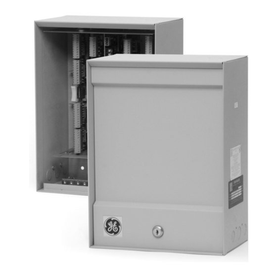
Enclosure (steel cabinet with keylock and tamper-
switch-protected door)
•
Power/Communications Board
•
PXNplus CPU Board
•
M5 Mounting hole template
•
M5 Controller Installation Sheet (this document)
•
PXNplus and DirecDoor Integrated Configuration Tool
Installation Sheet
•
Ferrite (for network connection)
•
M5 Mounting hole template
Documentation CD that includes the following documents:
•
M5 Controller Installation Manual
•
M5 Controller Installation Sheet
•
PXNplus and DirecDoor Integrated Configuration
Tool Installation Sheet
Power/Communications Board
The Power/Communications Board manages the power
and controls the communications for the controller. The
Power/Communications Board must be in the far right slot
of the controller.
For a detailed description of the Power/Communications
Board, refer to the M5 Controller Installation Manual.
Figure 1: Power/Communications Board layout
P/N 460639001B • ISS 21JUN09
1 of 6
Advertisement

Related Manuals for GE M5


Summary of Contents for GE M5
- Page 1 Power/Communications Board must be in the far right slot of the controller. For a detailed description of the Power/Communications Board, refer to the M5 Controller Installation Manual. Figure 1: Power/Communications Board layout Introduction This Installation Sheet is designed to help experienced technicians install the M5 controller quickly.
-
Page 2: Installation
Ferrite four times as shown in Figure 4. • The Power/Communications Board must be in the far right slot of the M5 card cage and grounded with a factory-installed braided wire as shown in Figure 5. Installation •... -
Page 3: Wiring The Power Supply
Figure 4: Ferrite installation Wiring the power supply The M5 requires a 12 to 15 VDC power supply with a 3 A current rating or greater depending on the configuration. Several M5 controllers can be powered by the same power supply. - Page 4 The battery backup acts as a temporary power supply to unit to connector J6 between pin 6 (ground) and pin 8 M5 when AC power is lost. Figure 8 shows a typical wiring (AC power fail input). The battery backup unit must...
-
Page 5: Troubleshooting
3 and 4. If the Power problems resistance is less than 200 ohms, there is a short Problem: The M5 does not power up correctly. from power to ground. Isolate the fault as follows: Resolution: Verify that the +5V and +12V LEDs on the •... - Page 6 6 of 6 P/N 460639001B • ISS 21JUN09...