
Related Manuals for Panasonic EP3202-U1


Summary of Contents for Panasonic EP3202-U1
-
Page 1: Specifications
ORDER NO.HPD0401U11C1 MASSAGE LOUNGER EP3203/EP3202-U1 SPECIFICATIONS © 2004 Matsushita Electric Works, Ltd. All rights reserved. Unauthorized copying and distribution is a violation of law. - Page 2 EP3203-U1 CONTENTS Page Page 1 COMPONENTS IDENTIFICATION 7 MOTION OF THE CLUTCH AND BELT BASED ON VARIOUS 2 MASSAGE RANGE (MOVEMENT RANGE OF MASSAGE MASSAGER OPERATIONS WHEELS) SHIATSU MASSAGE, SWEDISH MASSAGE, 8 CONTROL OF THE AIR-MASSAGE OPERATION KNEADING, VIBRATING, TAPPING A, TAPPING B, TAPPING 9 MASSAGER UP/DOWN SENSOR GEAR ADJUSTMENT C, WHOLE BACK ROLLING, REGIONAL ROLLING METHOD...
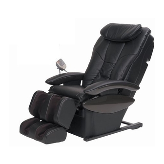
- Page 3 EP3203-U1 1 COMPONENTS IDENTIFICATION 1.1. Massage lounger...
- Page 4 EP3203-U1 1.2. Controller...
- Page 5 EP3203-U1 2 MASSAGE RANGE (MOVEMENT RANGE OF MASSAGE WHEELS) SHIATSU MASSAGE, SWEDISH MASSAGE, KNEADING, VIBRATING, TAPPING A, TAPPING B, TAPPING C, WHOLE BACK ROLLING, REGIONAL ROLLING Width adjustment Approx.50 to 210 mm (2.4in. to 8.3in.) Intensity adjustment Shiatsu, Swedish, Knead, vibration, Tap A, Tap B, Tap C, whole back roll, and Regional roll (from gentle to strong) :50mm(2.4in.)-wide adjustability where massage heads push out toward body as intensity increases.
-
Page 6: Turning On The Power
EP3203-U1 3 TURNING ON THE POWER 1. Plug the power plug into the power socket. 2. Turn the lock switch to the open position. 3. Turn on the power switch on the back of the unit. · When the operating lock switch is pointing toward ´lock´, the power switch cannot be moved to the ´on´ position. After each use. - Page 7 EP3203-U1 4 REQUIRED TOOLS...
- Page 8 EP3203-U1 5 ACTUAL WIRING DIAGRAM 5.1. Connecting cord for power source to Sub PCB...
- Page 9 EP3203-U1 6 DISPLAY METHOD OF MASSAGE BLOCK TOTAL USE TIME AND OPERATION TIME Adjustment of pressure sensor First, keep the Massage mechanism block unloaded with pressure and move it upward halfway. If the Massage mechanism block is at the highest or lowest position, you cannot arrange the pressure sensor correctly because the fabric becomes tense with pressure.
- Page 10 EP3203-U1 Chart for reading each function use time 7 MOTION OF THE CLUTCH AND BELT BASED ON VARIOUS MASSAGER OPERATIONS Massager operation and belt motion...
- Page 11 EP3203-U1 Massager operation and clutch motion...
- Page 12 EP3203-U1 8 CONTROL OF THE AIR-MASSAGE OPERATION Air massage functions with the operations of the pump unit x 1pc, 3-way electromagnetic valve x 1pc, and 2-way electromagnetic valve x 2pcs. 1. Air massage is operated by the pump and electromagnetic valves. 2.
- Page 13 EP3203-U1 9 MASSAGER UP/DOWN SENSOR GEAR ADJUSTMENT METHOD When the massager is removed from the chair, the position of the up/down sensor gear changes, resulting in a change of the up/down stop position. When installing the massager on the back frame, be sure to adjust the position with the up/down detection gear. Up/down sensor gear position adjustment procedure 1.
- Page 14 EP3203-U1 10 DISASSEMBLY AND ASSEMBLY INSTRUCTION 10.1. Removing the Arm rest and the Controller stand 10.1.1. Removing the Arm rest 1. Unscrew a hex screw (4mm) on the bottom of the Arm rest. 2. Pull the Arm rest backward(1) and pull it up(2) and take it away.
- Page 15 EP3203-U1 10.1.2. Removing the Controller stand 1. Take Controller, unscrew three screws(4mm) of the Controller stand.
- Page 16 EP3203-U1 10.2. Removing the Outside covers 10.2.1. Removing the Rear cover 1. Unscrew two screws at the top of the Rear cover top and two Push return rivets, and pull it off. 2. Take off the hook with nippers, which fixes the Rear cover bottom and the Rear cover fixing plate.
- Page 17 EP3203-U1 3. Take off two Brush clips on the Rear cover bottom and pull it off.
- Page 18 EP3203-U1 10.2.2. Removing the Under cover 1. Take off 8 push-return-rivets fixing Under cover left/right 2. Take off the Under covers right/left. and one brush clips (for Under cover right.) *When you take off the Under cover right, first take off the parts around the Power source box.
- Page 19 EP3203-U1 10.2.3. Removing the Side cover 1. Follow the procedure 10.2.1 Removing the Rear cover and 10.2.2. Removing the Under cover. 2. Unscrew three srew-rivets. 3. Unhook two hooks on the top of the Side cover and take off the Side cover. Caution When installing the Side cover, first hook two hooks and then screw screw-rivets.
- Page 20 EP3203-U1 10.3. Removing the Massage mechanism block Move the Massage mechanism block to the lowest position by the Upward button. Be sure to lean the Massage chair on chairs or desk so that the work will be easy. 1. Unscrew four screws on the Rear cover fixing plate. 2.
- Page 21 EP3203-U1 4. Pinch the hook of the Insulated tie and remove it. 5. Remove the Connecting cord for power source from the Cover clip. 6. Remove Rail piece set at both sides.
- Page 22 EP3203-U1 10.4. Removing the Under box and the Under box cover 1. Follow the procedure 10.2.1 Removing the Under cover. 2. Lift the Ottoman and put it on some desk and unscrew three screws on the Under box top/left and float the Under box top/left.
- Page 23 EP3203-U1 5. Remove the Sub PCB. 6. Unscrew three screws on the Under box and pull out the Under box. Be careful how Ottoman hoses are going out. Be sure that all hooks are hooked.
- Page 24 EP3203-U1 10.5. Removing the Lift units 10.5.1. Removing the Ottoman lift unit 1. Follow the procedure 10.3 Removing the Massage mechanism block. *It is safer to unload the Massage mechanism block. 2. Follow the procedure 10.3 Removing the Under cover. 3.
- Page 25 EP3203-U1 10.5.2. Removing the Reclining lift unit 1. Follow the procedure 10.3 Removing the Massage mechanism block. *It is safer to unload the Massage mechanism block. 2. Follow the procedure 10.3 Removing the Under cover. 3. Follow the procedure 10.4 Removing the Under box and the Under box cover 1 to 4, and disconnect the connectors blue(CN102- CN111) connecting to the Sub PCB.
- Page 26 EP3203-U1 10.6. Removing the Seat 1. Follow the procedure 10.2.1 Removing the Rear cover, 10.1.1 Removing the Arm rest, and 10.2 Removing the Outside covers. 2. Unhook the hooks at both sides of the Seat. 3. Cut off the Insulated tie and unzip the zippers of the Seat and the Ottoman and unscrew one each Push return rivets on both sides, and take off the Seat.
- Page 27 EP3203-U1 10.7. Removing the Air Ottoman 10.7.1. Removing the Air Ottoman 1. Follow the procedure 10.4 Removing the Under Cover. 2. Follow the procedure 10.6 Removing the Seat 3 and unzip the zippers and the Push return rivet of the Seat and the Ottoman.
- Page 28 EP3203-U1 5. Unscrew a screw and take off the Wire fixing plate. 6. Unhook the hook of the wire from the Leg slide lever and pull off the wire. 7. Move the Hose clamps and pull off the Hoses and take off the two Rod holders.
- Page 29 EP3203-U1 Caution when installing Be sure not to make the hook side of the Rod holder face the Seat, which might cause the tear. 8. Remove four Lift bushings and four Snap pins, and take off the Parallel link.
- Page 30 EP3203-U1 9. Take off the left/right Hinge pin Bs, Washers, and U nuts, and you can take off the Ottoman. 10. Pull out the Snap pin from the Ottoman and remove the Parallel link. Caution when installing Be careful of the directions when installing the Parallel link.
- Page 31 EP3203-U1 11. Unscrew three screws each at both sides of the Slide guide.
- Page 32 EP3203-U1 12. Unscrew two screws and remove the Spring.
- Page 33 EP3203-U1 10.7.2. Removing the Air Ottoman fabric 1. Follow the procedure 10.7.1 Removing the Ottoman. 2. Unzip the Zippers(two) of the bottom of the Air Ottoman. 3. Cut off the Insulated tie on the Hose for sole, and pull off the Hose from the fabric.
- Page 34 EP3203-U1 4. Remove the Fabric. Caution when installing *Be careful of the hole of the Fabric in which the Hose goes in when installing the Fabric.
- Page 35 EP3203-U1 10.7.3. Removing the Air Ottoman inside (Air bags, Hoses) 1. Follow the procedure 10.7.1 Removing the Air Ottoman and the procedure 10.7.2 Removing the Air Ottoman fabric. 2. Cut off all the Insulated ties binding Hoses. When installing the Insulated ties, refer to the 10.7.4 Air Ottoman hoses. 3.
- Page 36 EP3203-U1 10.7.4. Air Ottoman hoses...
- Page 37 EP3203-U1 10.8. Removing the Head rest, Back cushion, and Massage wheel cover 10.8.1. Removing the Head rest 1. Remove the Head rest. 10.8.2. Removing the Back cushion 1. Unzip the Zippers and remove the Back cushion.
- Page 38 EP3203-U1 10.8.3. Removing the Massage wheel cover *You can work without unloading the Massage mechanism block. 1. Follow the procedure 10.2.1 Removing the Back cover. 2. Cut off the three Insulated ties on the Seat panel. 3. Unscrew eight screws on the Massage wheel cover and remove the Massage wheel cover.
- Page 39 EP3203-U1 10.9. Removing the Power source box 1. Unscrew a screw and remove the Bushing cover. Pull out the Controller cord and disconnect the Connector and you can remove the Controller block. *Use a screwdriver so as not to break the screw head. 2.
- Page 40 EP3203-U1 3. Micro switch, Fuses, Power cord, and switch can be removed. *Be careful not to break the screw heads. Caution when installing Controller cord and Power cord Refer to the figure when installing cords. Caution when removing and installing the Power cord Cut the Insulated time at two parts as the figure and use the new Insulated tie and fix the Power cord.
- Page 41 EP3203-U1 10.10. Adjustment of the Up/down sensor gear When the Massage mechanism block is removed from the chair, the position of the Up/down sensor gear changes resulting in a change of the up/down stop position. When installing the Massage mechanism block on the back frame, be sure to adjust the position with the Up/down sensor gear. *Up/down sensor gear position adjustment procedure To make an adjustment, refer to the Massage mechanism block removing method (the back frame is tilted from the chair).
- Page 42 EP3203-U1 10.11. Installing the Connecting cord for power source Move the Massage mechanism block to the highest position. *After installing each Connecting cords, be sure to confirm that each Connecting cords do not touch belts or Rear cover fixing plate or being stuck in the gear by operating the Up/down button in the controller manual mode. Also confirm that each Connecting cords are not extremely tense at the highest position.
- Page 43 EP3203-U1 10.12. Lead wires of Massage mechanism block Refer to the following figure for the fixing of the Main PCB, motors, sensors, parts, and Insulated ties.
- Page 44 EP3203-U1 10.13. Assembly and disassembly of Massage mechanism block 10.13.1. Removing the Up/down sensor 1. Disconnect the Connector (CN206)(1) on the Main PCB. 2. Cut off the Insulated tie medium (2) of the lead wires. 3. Unscrew two installation screws (3) of the Up/down gear box B and the Up/down sensor plate and remove the Up/down sensor. Caution when installing When installing the Up/down sensor, be sure to insert the Sensor plate to the groove of the Up/down gear box B.
- Page 45 EP3203-U1 10.13.4. Removing the Width sensor 1. Disconnect all the Connectors on the Main PCB. 2. Cut off the four Insulated ties medium (2) (5) (10) (18), one small (12). 3. Unscrew five screws (13) on the Main PCB installation plate and four screws (14) and three screws (15). 4.
- Page 46 EP3203-U1 10.13.6. Removing the Air unit 1. Disconnect Connectors (CN201, CN208) of the Main PCB. 2. Unscrew five screws of the Main PCB installation plate and four screws of the Air unit. 3. Cut off the Insulated tie medium of the Air hoses. Caution when installing ·...
- Page 47 EP3203-U1 10.13.9. Removing the Up/down gear block *You should disassemble the Up/down gear block before replacing the Up/down shaft and the Up/down motor. *Follow the procedure 10.13.4 Removing the Width sensor 1-3. 1. Remove the Massage mechanism block from the Rear frame. 2.
- Page 48 EP3203-U1 10.13.10. Removing the Intensity gear block *Follow the procedure 10.13.4 Removing the Width sensor 1-3. *Follow the procedure 10.13.10 Removing the Up/down gear block 1-3. 1. Unscrew five screws of the Intensity gear box and the Intensity driving installation plate. 2.
- Page 49 EP3203-U1 10.13.11. Removing the Width driving block *Follow the procedure 10.13.4 Removing the Width sensor 1-3. *Follow the procedure 10.13.10 Removing the Up/down gear box 1-3. 1. Take off the clamps of the Shoulder air bag hose 1.2 and remove the Width driving block. 2.
- Page 50 EP3203-U1 11 ACTUAL WIRING DIAGRAM 11.1. Air Ottoman...
- Page 51 EP3203-U1...
- Page 52 EP3203-U1 12 CHECKING 12.1. Controller, Massage mechanism block...
- Page 53 EP3203-U1...
- Page 54 EP3203-U1...
- Page 55 EP3203-U1...
- Page 56 EP3203-U1 12.2. Air bags...
- Page 57 EP3203-U1 12.3. Checking the pressure of the Air bags 1. Follow the procedure 10.4 Removing the Under cover. 2. Connect the Air pressure gauge and the Special hose to the Hose 2-row leg A. 3. Turn on the On/off switch of the Controller and push the Squeeze button.
- Page 58 EP3203-U1 12.4. Checking Electromagnetic valves Follow the procedure 10.4 Removing the Under cover and 10.4 Removing the Under box, Under box cover. 1. Turn on the On/off switch of the Controller and push the Squeeze button. 2. Disconnect the Hoses with the air flow and the operating voltages of the Electromagnetic valves.
- Page 59 EP3203-U1 13 GREASE...
- Page 60 EP3203-U1...
- Page 61 EP3203-U1 14 EXPLODED VIEW...
- Page 62 EP3203-U1...
- Page 63 EP3203-U1...
- Page 64 EP3203-U1...
- Page 65 EP3203-U1...
- Page 66 EP3203-U1...
- Page 67 EP3203-U1...
- Page 68 EP3203-U1 15 REPLACEMENT PARTS LIST NOTES: Ref.No. Part No. Part Name & Description Remarks Per Unit WEP3200L0087 BACK FRAME WEP3200L0887 RESIN BUSHING WEP3203L0048 REAR COVER FIXING PLATE WEP2000L9567 SCREW(CUP.K4-10) WEP2005L0687 CORD WIRE WEP3200L0767 RAIL PIECE RIGHT EP3200L0777 RAIL PIECE LEFT WEP573L6627 SCREW(CUP.S.K4-6) WEP3200L3027...
- Page 69 EP3203-U1 Ref.No. Part No. Part Name & Description Remarks Per Unit WEP2110H3127 BUSHING COVER WEP3203K2008 POWER SOURCE SWITCH BLOCK WEP3203K2058 POWER CORD WEP3203K2068 CONNECTING CORD FOR POWER SOURCE B WEP3200L0077 POWER SOURCE BOX LID WEP3203K2078 CONNECTING CORD FOR CONTROLLER WEP2000L0717 ROD HOLDER C WEP3203K3108 UNDER BOX TOP/RIGHT...
- Page 70 EP3203-U1 Ref.No. Part No. Part Name & Description Remarks Per Unit WEP3203L4538 UP/DOWN GEAR BLOCK WEP3200L0377 UP/DOWN SHAFT WEP596L6057 UP/DOWN SHAFT BOLT WEP3200L3537 FITTING WEP3200L1457 GUIDE ROLLER C BLOCK WEP545H1937 GUIDE ROLLER B WEP2200L1907 PINION C SPRING WEP578AL0317 RUBBER RING WEP3200L1447 PINION C WEP3200L1477...
- Page 71 EP3203-U1 Ref.No. Part No. Part Name & Description Remarks Per Unit WEP760N9607 SCREW(K4-10) WEP590L6017 SCREW(CUP.S.K3-6) WEP573L6627 SCREW(CUP.S.K.4-6) WEP2110L0427 RIVET 21M2 WEP3200L0437 PLATE STOPPER RIGHT WEP3200L0447 PLATE STOPPER LEFT WEP3200L0417 PLATE STOPPER COVER WEP3200L0387 PROTECTION CLOTH WEP3200K0457 BRUSHCLIP WEP3200L0037 PCB INSTALLATION BOARD WEP3200L0517 PCB SPACER WEP2000L6967...