Sony ZS-H10CP Service Manual
Personal audio system
Hide thumbs
Also See for ZS-H10CP:
- Operating instructions (2 pages) ,
- Specifications (2 pages) ,
- Operating instructions manual (11 pages)
Table of Contents
Advertisement
ZS-H10CP/H20CP
SERVICE MANUAL
Ver. 1.0 2006.03
AUDIO POWER SPECIFICATIONS
(H10CP: US model only)
P
OWER OUTPUT AND TOTAL HARMONIC DISTORTION:
With 3.2-ohm loads, both channels driven from 150 - 10 000 Hz; rated 1.4 W
per channel-minimum RMS power, with no more than 10 % total harmonic
distortion in AC operation.
Other specifications
CD player section
System
Compact disc digital audio system
Laser diode properties
Emission duration: Continuous
Laser output: Less than 44.6 µW
(This output is the value measured at a distance of
about 200 mm from the objective lens surface on the
optical pick-up block with 7 mm aperture.)
Number of channels
2
Frequency response
20 - 20 000 Hz 1 dB
Wow and flutter
Below measurable limit
Radio section
Frequency range
FM: 87.5 - 108 MHz
– H10CP/H20CP: Mexican model –
AM: 530 - 1 710 kHz
– H20CP: E model –
AM: 531 - 1 611 kHz (9 kHz step)
530 - 1 610 kHz (10 kHz step)
Antennas
FM: Telescopic antenna
AM: Built-in ferrite bar antenna
General
Speaker
7
inches) dia., 3.2 Ω, cone type (2) (H10CP)
Full range: 10 cm (3
/
8
inches) dia., 6 Ω, cone type (2) (H20CP)
7
Full range: 10 cm (3
/
8
Sony Corporation
9-887-131-01
Personal Audio Division
2006C05-1
© 2006.03
Published by Sony Techno Create Corporation
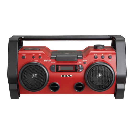
Photo: ZS-H10CP
Model Name Using Similar Mechanism
Optical Pick-up Mechanism Type
SPECIFICATIONS
Inputs
AUDIO IN jack (stereo minijack): minimum input level 245 mV
Outputs
Headphones jack (stereo minijack):
For 16 - 68 Ω impedance headphones
Power output
2.3 W + 2.3 W (at 3.2 Ω, 10 % harmonic distortion) (H10CP)
4.5 W + 4.5 W (at 6 Ω, 10 % harmonic distortion) (H20CP)
Power requirements
DC IN 9 V jack accepts:
Supplied AC power adaptor for use with 120 V AC, 60 Hz (H10CP/H20CP: Mexican model)
Supplied AC power adaptor for use with 230 V AC, 50 Hz (H20CP: E model)
9 V DC, 6 R20 (size D) batteries
Battery life
CD playback
Sony R20P: approx. 3 h (H10CP), approx. 1 h (H20CP)
Sony alkaline LR20: approx. 10 h (H10CP), approx. 6 h (H20CP)
Radio reception
Sony R20P: approx. 14 h (H10CP), approx. 4 h (H20CP)
Sony alkaline LR20: approx. 28 h (H10CP), approx. 13 h (H20CP)
Dimensions
Approx. 558 × 292 × 275 mm (w/h/d)
(22 × 11
× 10
1
7
/
/
inches) (incl. projecting parts)
2
8
Mass
Approx. 6.4 kg (14 lb) (incl. batteries)
Supplied accessories
AC power adaptor (1)
Design and specifications are subject to change without notice.
PERSONAL AUDIO SYSTEM
US Model
Canadian Model
ZS-H10CP
E Model
ZS-H20CP
CFD-S01
KSM-213CDP
Advertisement
Table of Contents

Related Manuals for Sony ZS-H10CP


Summary of Contents for Sony ZS-H10CP
-
Page 1: Specifications
7 mm aperture.) Sony R20P: approx. 3 h (H10CP), approx. 1 h (H20CP) Number of channels Sony alkaline LR20: approx. 10 h (H10CP), approx. 6 h (H20CP) Radio reception Frequency response 20 - 20 000 Hz 1 dB Sony R20P: approx. -
Page 2: Table Of Contents
THE PARTS LIST ARE CRITICAL TO SAFE OPERATION. FONCTIONNEMENT. NE REMPLACER CES COM- POSANTS REPLACE THESE COMPONENTS WITH SONY PARTS WHOSE QUE PAR DES PIÈCES SONY DONT LES NUMÉROS SONT PART NUMBERS APPEAR AS SHOWN IN THIS MANUAL OR DONNÉS DANS CE MANUEL OU DANS LES SUPPLÉMENTS IN SUPPLEMENTS PUBLISHED BY SONY. -
Page 3: Servicing Notes
ZS-H10CP/H20CP SECTION 1 SERVICING NOTES UNLEADED SOLDER NOTES ON HANDLING THE OPTICAL PICK-UP Boards requiring use of unleaded solder are printed with the lead- BLOCK OR BASE UNIT free mark (LF) indicating the solder contains no lead. The laser diode in the optical pick-up block may suffer electrostatic... -
Page 4: General
ZS-H10CP/H20CP SECTION 2 This section is extracted from instruction manual. GENERAL Basic Operations Notes on MP3 discs Do this • When the disc is inserted, the unit reads all the files on that disc. Pause playback Press . To resume play, press During this time, “READING”... -
Page 5: Other Operations
ZS-H10CP/H20CP Other Operations Tips Programmed 1 Program tracks/MP3 files (see Using the display • If you try to program 16 tracks/MP3 files or more, “FULL” will tracks/MP3 “Creating your own program”). appear in the display. files 2 Press REPEAT until “ ” and You can check information about the CD using the •... -
Page 6: Disassembly
ZS-H10CP/H20CP SECTION 3 DISASSEMBLY • This set can be disassembled in the order shown below. 3-1. DISASSEMBLY FLOW Note 1: The process described in can be performed in any order. Note 2: Without completing the process described in , the next process can not be performed. -
Page 7: Base (Handle L)/(Handle R), Handle Assy
ZS-H10CP/H20CP Note: Follow the disassembly procedure in the numerical order given. 3-2. BASE (HANDLE L)/(HANDLE R), HANDLE ASSY 8 screw (B2.6) (BV) 6 six screws (hexagon hole) qa telescopic antenna 4 screw (B2.6) (BV) 5 handle assy qs harness qd holder (ANT) 3 base (handle R) q;... -
Page 8: Cd Block Assy
ZS-H10CP/H20CP 3-4. CD BLOCK ASSY 3 two screws (B2.6) (BV) 1 connector (CN803) 6 CD block assy 2 flexible flat cable (23core) (CN802) 5 four screws (B2.6) (PWH) 3-5. OPTICAL PICK-UP (KSM-213CDP) 1 CD cover 2 two vibration proof rubbers... -
Page 9: Power Board
ZS-H10CP/H20CP 3-6. POWER BOARD 1 two connectors (CN301,908) 5 four screws (B2.6) (BV) 7 POWER board 2 connector (CN302) 3 four screws (B2.6) (BV) 6 two holders (PWB) 3-7. MAIN BOARD 3 connector (CN404) 4 connector 5 connector (CN303) (CN403) -
Page 10: Key (Power)/(Line) Board, Jack Board
ZS-H10CP/H20CP 3-8. KEY (POWER)/(LINE) BOARD, JACK BOARD 1 two screws (B2.6) (BV) qf KEY (POWER) board 2 screw (B2.6) (BV) qs button (power) 6 JACK board 5 two screws (B2.6) (BV) qd two screws (B2.6) (BV) 0 two screws 4 connector (B2.6) (BV) -
Page 11: Key (Play) Board
ZS-H10CP/H20CP 3-10. KEY (PLAY) BOARD 3 button (function) 4 two screws (B2.6) (BV) 1 four screws (B2.6) (BV) 5 KEY (PLAY) board 3-11. TU BOARD 1 flexible flat cable (11core) 3 four screws (CNP1) (B2.6) (BV) 6 TU board 4 holder (PWB) 5 holder (PWB) 2 four screws (B2.6) (BV) -
Page 12: Dc Jack Board
ZS-H10CP/H20CP 3-12. DC JACK BOARD 1 sheet (blind D) 4 connector (CN902) 3 connector (CN903) 2 sheet (blind D) 7 two screws (B2.6) (BV) 9 connector (CN904) 0 DC JACK board 5 four screws (B2.6) (BV) -
Page 13: Test Mode
ZS-H10CP/H20CP SECTION 4 TEST MODE COLD RESET Procedure: 1. In the standby mode or power on status, press three buttons of [POWER], [TUNE/FOLDER -], simultaneously. 2. The set is reset and display “RESET”, then becomes standby status. PANEL TEST MODE Procedure: 1. -
Page 14: Electrical Adjustments
ZS-H10CP/H20CP SECTION 5 ELECTRICAL ADJUSTMENTS 0 dB=1 µV TUNER SECTION AM IF ADJUSTMENT Adjust for a maximum reading on level meter [AM] 450 kHz Setting: Function: RADIO ( ): H20CP: E model Band: AM AM FREQUENCY COVERAGE ADJUSTMENT Adjustment Part... - Page 15 ZS-H10CP/H20CP Adjustment and Connecting Location: CD SECTION – TU Board (Component Side) – Note: 1. CD Block is basically constructed to operate without adjustment. 2. Use PATD-012 disc (Part No. 4-225-203-01) unless otherwise T2 FM IF Adjustment indicated. 3. Use an oscilloscope with more than 10 MΩ impedance.
-
Page 16: Diagrams
ZS-H10CP/H20CP SECTION 6 DIAGRAMS 6-1. BLOCK DIAGRAM – CD SERVO Section – A+3.3V DETECTOR (CD) CD-L (Page 18) 58 B AOUT1 RFACO 71 RFACI PCMD 4 PCMDI 59 C AOUT2 R-CH 6 BCKI R-ch is omitted due to same as L-ch. -
Page 17: Block Diagram - Tuner Section
ZS-H10CP/H20CP 6-2. BLOCK DIAGRAM – TUNER Section – FM IFT FM/AM RF AMP, MIX, OSC, FM/AM IF AMP, DET, MPX FM IF ANT1 FM TELESCOPIC ANTENNA L-OUT RA-L IF-IN RF-IN MIX-OUT FM IF (Page 18) -OUT RF AMP MUTE BUFFER... -
Page 18: Block Diagram - Main Section
ZS-H10CP/H20CP 6-3. BLOCK DIAGRAM – MAIN Section – R-CH MEGA BASS CONTROL (H20CP) Q160 J301 R-CH AUDIO IN R-CH R-CH 20 21 LI-L POWER AMP (H10CP) IC101 CD-L CD-L SELL ELECTRICAL SOUND (Page 16) VOLUME CONTROL J302 RA-L RA-L (Page 17... - Page 19 ZS-H10CP/H20CP • Note for Printed Wiring Boards and Schematic Diagrams • Circuit Boards Location Note on Printed Wiring Board: Note on Schematic Diagram: • X : parts extracted from the component side. • All capacitors are in µF unless otherwise noted. (p: pF) •...
-
Page 20: Printed Wiring Board - Cd Board
ZS-H10CP/H20CP • See page 19 for Circuit Boards Location. 6-4. PRINTED WIRING BOARD – CD Board – : Uses unleaded solder. CD BOARD (COMPONENT SIDE) CD BOARD M401 (SPINDLE) (CONDUCTOR SIDE) S201 (LIMIT) C403 R280 C405 C406 R451 IC402 R104... -
Page 21: Schematic Diagram - Cd Board
ZS-H10CP/H20CP • See page 32 for Waveforms. • See page 32 for IC Block Diagrams. • See page 35 for IC Pin Function Description. 6-5. SCHEMATIC DIAGRAM – CD Board – C210 C208 (RFACO) C230 R256 100p C257 C274 CN301... -
Page 22: Printed Wiring Board - Tu Board
ZS-H10CP/H20CP • See page 19 for Circuit Boards Location. 6-6. PRINTED WIRING BOARD – TU Board – : Uses unleaded solder. TU BOARD AM FERRITE-ROD ANTENNA ANT1 FM TELESCOPIC ANTENNA (VT) (ANT) (EXCEPT H20CP: E) (GND) JC24 H20CP: E ) -
Page 23: Schematic Diagram - Tu Board
ZS-H10CP/H20CP • See page 32 for Waveforms. • See page 32 for IC Block Diagrams. 6-7. SCHEMATIC DIAGRAM – TU Board – AM FERRITE-ROD KV1520NT 220p AM OSC ANTENNA AM FREQUENCY 100p COVERAGE JC24 JC12 JC11 1µH 0.01 220k (VT) 1000p 0.01... -
Page 24: Printed Wiring Boards - Main Section
ZS-H10CP/H20CP • See page 19 for Circuit Boards Location. • See page 25 for Semiconductor Location. 6-8. PRINTED WIRING BOARDS – MAIN Section – : Uses unleaded solder. (Page 26) (Page 26) (Page 31) (Page 30) MAIN BOARD KEY (PLAY) -
Page 25: Schematic Diagram - Main Section
ZS-H10CP/H20CP • See page 32 for Waveforms. • See page 32 for IC Block Diagrams. • See page 35 for IC Pin Function Description. 6-9. SCHEMATIC DIAGRAM – MAIN Section – ∗ ∗ C830 C829 C101,201 C104,204 4.7 50V(H10CP) 0.47 50V(H10CP) -
Page 26: Printed Wiring Board - Power Supply Section (1/2)
ZS-H10CP/H20CP • See page 19 for Circuit Boards Location. 6-10. PRINTED WIRING BOARD – POWER SUPPLY Section (1/2) – : Uses unleaded solder. • Semiconductor Location Ref. No. Location D303 (Page 27) D360 JACK BOARD POWER BOARD D361 CN305 D950... -
Page 27: Printed Wiring Boards - Power Supply Section (2/2)
ZS-H10CP/H20CP • See page 19 for Circuit Boards Location. 6-11. PRINTED WIRING BOARDS – POWER SUPPLY Section (2/2) – : Uses unleaded solder. J901 DC JACK BOARD – DC IN 9V FH901 J301 J302 AUDIO IN JACK BOARD F901 D901... -
Page 28: Schematic Diagram - Power Supply Section
ZS-H10CP/H20CP 6-12. SCHEMATIC DIAGRAM – POWER SUPPLY Section – POWER AMP IC101 BA5417 CN306 L201 C227 C228 (Page 25) 10µH 2200p 1000p R238 R239 2.2k 4.7k (H10CP) R149 C207 L101 1000p 10µH J301 JC314 AUDIO IN C133 JW127 (H20CP) (H10CP) -
Page 29: Schematic Diagram - Panel Section
ZS-H10CP/H20CP 6-13. SCHEMATIC DIAGRAM – PANEL Section – R426 R427 R415 R416 R417 S419 ROTARY ENCODER R494 R409 R408 R428 R429 VOLUME R430 D401 S413 S414 S415 L-34HD R493 OPR/BATT RADIO S408 S407 BAND CN414 AUTO PRESET R422 TUNE/FOLDER (Page 25) -
Page 30: Printed Wiring Boards - Panel Section (1/2)
ZS-H10CP/H20CP • See page 19 for Circuit Boards Location. 6-14. PRINTED WIRING BOARDS – PANEL Section (1/2) – : Uses unleaded solder. KEY (PRESET) BOARD KEY (TUNE) BOARD S409 MEGA BASS (Page 24) MAIN BOARD CN403 S408 TUNE/FOLDER R411 S410 R430 >... -
Page 31: Printed Wiring Boards - Panel Section (2/2)
ZS-H10CP/H20CP • See page 19 for Circuit Boards Location. 6-15. PRINTED WIRING BOARDS – PANEL Section (2/2) – : Uses unleaded solder. (Page 24) KEY (PLAY) BOARD MAIN BOARD JOG BOARD CN404 S415 RADIO S413 S414 BAND AUTO PRESET S419... - Page 32 ZS-H10CP/H20CP • Waveforms • IC Block Diagrams – TU Board – – MAIN Board – – CD Board – – CD Board – IC203 BH18LB1WG-TR IC201 1 (LRCK), 2 (LRCKI) IC2 w; (XOUT) IC801 os (X1) (CD play mode) VIN 1...
- Page 33 ZS-H10CP/H20CP – TU Board – IC1 TA2149BN RF GND FM RFOUT FM RF RF VCC FM RFIN AM RFIN AM LOW CUT MIX OUT FM OSC AM OSC BUFF BUFF 1/1 OR 1/16 OSC OUT LEVEL AM IF AM IF IN...
- Page 34 ZS-H10CP/H20CP – MAIN Board – IC301 BD3870FS-E2...
- Page 35 ZS-H10CP/H20CP • IC Pin Function Description CD BOARD IC201 CXD3014A-201R (CD DSP) Pin No. Pin Name Description LRCK L/R sampling clock signal output terminal LRCKI L/R sampling clock signal input terminal PCMD Serial data output terminal PCMDI Serial data input terminal...
- Page 36 ZS-H10CP/H20CP Pin No. Pin Name Description FRDR Focus servo drive signal (-) output terminal IOVDD1 Power supply terminal (+3.3V) AVDD0 Power supply terminal (+3.3V) AVSS0 Ground terminal E signal input from the optical pick-up block F signal input from the optical pick-up block...
- Page 37 ZS-H10CP/H20CP Pin No. Pin Name Description SVDD Power supply terminal (+2.5V) JTAGTCK Clock signal input terminal (for JTAG) Not used JTAGTDI Data input terminal (for JTAG) Not used JTAGTDO Data output terminal (for JTAG) Not used JTAGTMS Mode select signal input terminal (for JTAG) Not used...
- Page 38 ZS-H10CP/H20CP MAIN BOARD IC801 MB90802NPF-G-117E1 (SYSTEM CONTROLLER) Pin No. Pin Name Description O-POWER System power on/off control signal output terminal "H": power on O-FM/AM-SHIFT Oscillation frequency selection on/off control signal output terminal "H": selection on O-A-MUTE Audio muting on/off control signal output terminal "H": muting on CD-XRST System reset signal output to the CD DSP "L": reset...
- Page 39 ZS-H10CP/H20CP Pin No. Pin Name Description I-VM Input terminal for battery middle point voltage detection I-SHIMUKE Input terminal for destination discrimination I-ENCODER +, 49, 50 Jog dial pulse input from the rotary encoder (VOLUME) I-ENCODER - Input terminal for mode setting "L": normal mode, "H": flash writing mode Input terminal for mode setting "H": normal and flash writing mode...
-
Page 40: Exploded Views
ZS-H10CP/H20CP SECTION 7 EXPLODED VIEWS NOTE: • -XX and -X mean standardized parts, so they • Items marked “*” are not stocked since they The components identified by mark 0 or dotted line with mark 0 are may have some difference from the original are seldom required for routine service. -
Page 41: Cabinet Section
ZS-H10CP/H20CP 7-2. CABINET SECTION cabinet (rear) assy section cabinet (upper) assy section not supplied chassis assy section Ref. No. Part No. Description Remark Ref. No. Part No. Description Remark 3-254-140-11 SCREW (B2.6), (+) BV TAPPING 2-666-199-01 LID, BATTERY CASE 2-666-200-01 LID, AC BOX... -
Page 42: Chassis Assy Section
ZS-H10CP/H20CP 7-3. CHASSIS ASSY SECTION Note:This illustration displays the back of the set forward. TU board not supplied not supplied holder assy section LCD401 (H10CP) MAIN board Ref. No. Part No. Description Remark Ref. No. Part No. Description Remark A-1176-957-A MAIN BOARD, COMPLETE (H10CP) -
Page 43: Holder Assy Section
ZS-H10CP/H20CP 7-4. HOLDER ASSY SECTION Note:This illustration displays the back of the set forward. speaker section not supplied not supplied not supplied not supplied not supplied not supplied not supplied not supplied not supplied not supplied not supplied not supplied... -
Page 44: Speaker Section
ZS-H10CP/H20CP 7-5. SPEAKER SECTION Note:This illustration displays the back of the set forward. not supplied not supplied not supplied SP101 not supplied not supplied SP201 Ref. No. Part No. Description Remark Ref. No. Part No. Description Remark 3-252-827-11 SCREW (B2.6), (+) BV TAPPING... -
Page 45: Cabinet (Upper) Assy Section
ZS-H10CP/H20CP 7-6. CABINET (UPPER) ASSY SECTION not supplied not supplied not supplied not supplied not supplied CD block assy section Ref. No. Part No. Description Remark Ref. No. Part No. Description Remark 3-252-828-01 SCREW (B2.6), (+) PWH TAPPING 2-669-039-01 SHAFT (BUCKLE) 3-252-827-11 SCREW (B2.6), (+) BV TAPPING... -
Page 46: Cd Block Assy Section
ZS-H10CP/H20CP 7-7. CD BLOCK ASSY SECTION S201 Ref. No. Part No. Description Remark Ref. No. Part No. Description Remark A-1134-279-A CD BOARD, COMPLETE 1-832-404-21 CABLE, FLEXIBLE FLAT (16 CORE) 3-931-379-21 RUBBER, VIBRATION PROOF (GREEN) S201 1-771-853-11 SWITCH, DETECTION (LIMIT) 0 303... -
Page 47: Cabinet (Rear) Assy Section
ZS-H10CP/H20CP 7-8. CABINET (REAR) ASSY SECTION BATTERY (2) board supplied supplied not supplied DC JACK F901 board Ref. No. Part No. Description Remark Ref. No. Part No. Description Remark 2-666-220-01 HOLDER (DC) 2-669-030-01 CAP (DC) 3-252-827-11 SCREW (B2.6), (+) BV TAPPING... -
Page 48: Electrical Parts List
ZS-H10CP/H20CP SECTION 8 BATTERY (1) BATTERY (2) ELECTRICAL PARTS LIST NOTE: • Due to standardization, replacements in the • Items marked “*” are not stocked since they The components identified by mark 0 or dotted line with mark 0 are parts list may be different from the parts are seldom required for routine service. - Page 49 ZS-H10CP/H20CP DC JACK DETECTION JACK Ref. No. Part No. Description Remark Ref. No. Part No. Description Remark C406 1-164-360-11 CERAMIC CHIP 0.1uF C424 1-164-360-11 CERAMIC CHIP 0.1uF R323 1-216-864-11 SHORT CHIP R324 1-216-845-11 METAL CHIP 100K 1/10W C451 1-165-176-11 CERAMIC CHIP 0.047uF...
- Page 50 ZS-H10CP/H20CP JACK KEY (LINE) KEY (PLAY) KEY (POWER) KEY (PRESET) KEY (TUNE) Ref. No. Part No. Description Remark Ref. No. Part No. Description Remark C246 1-162-927-11 CERAMIC CHIP 100PF A-1176-946-A KEY (PLAY) BOARD, COMPLETE C314 1-107-826-11 CERAMIC CHIP 0.1uF **************************...
- Page 51 ZS-H10CP/H20CP KEY (TUNE) MAIN Ref. No. Part No. Description Remark Ref. No. Part No. Description Remark C112 1-162-962-11 CERAMIC CHIP 470PF < RESISTOR > C113 1-165-176-11 CERAMIC CHIP 0.047uF R408 1-216-813-11 METAL CHIP 1/10W C114 1-127-715-11 CERAMIC CHIP 0.22uF R409...
- Page 52 ZS-H10CP/H20CP MAIN Ref. No. Part No. Description Remark Ref. No. Part No. Description Remark C822 1-162-927-11 CERAMIC CHIP 100PF < IC > C823 1-162-927-11 CERAMIC CHIP 100PF C824 1-162-927-11 CERAMIC CHIP 100PF IC301 6-701-824-11 IC BD3870FS-E2 C825 1-162-927-11 CERAMIC CHIP...
- Page 53 ZS-H10CP/H20CP MAIN Ref. No. Part No. Description Remark Ref. No. Part No. Description Remark R213 1-216-853-11 METAL CHIP 470K 1/10W R802 1-216-821-11 METAL CHIP 1/10W R803 1-216-821-11 METAL CHIP 1/10W R214 1-216-849-11 METAL CHIP 220K 1/10W R804 1-216-821-11 METAL CHIP...
- Page 54 ZS-H10CP/H20CP MAIN POWER Ref. No. Part No. Description Remark Ref. No. Part No. Description Remark R868 1-216-821-11 METAL CHIP 1/10W C136 1-107-826-11 CERAMIC CHIP 0.1uF C137 1-104-665-11 ELECT 100uF R869 1-216-821-11 METAL CHIP 1/10W C138 1-107-826-11 CERAMIC CHIP 0.1uF R870...
- Page 55 ZS-H10CP/H20CP POWER Ref. No. Part No. Description Remark Ref. No. Part No. Description Remark C952 1-126-963-11 ELECT 4.7uF R126 1-216-829-11 METAL CHIP 4.7K 1/10W (H10CP) C954 1-162-970-11 CERAMIC CHIP 0.01uF C955 1-126-935-11 ELECT 470uF R127 1-216-845-11 METAL CHIP 100K 1/10W...
- Page 56 ZS-H10CP/H20CP POWER Ref. No. Part No. Description Remark Ref. No. Part No. Description Remark (H20CP) 1-162-970-11 CERAMIC CHIP 0.01uF R237 1-216-789-11 METAL CHIP 1/10W (H20CP: E) (H20CP) 1-164-227-11 CERAMIC CHIP 0.022uF R238 1-216-825-11 METAL CHIP 2.2K 1/10W (EXCEPT H20CP: E)
- Page 57 ZS-H10CP/H20CP Ref. No. Part No. Description Remark Ref. No. Part No. Description Remark 1-216-813-11 METAL CHIP 1/10W < DIODE > 1-216-809-11 METAL CHIP 1/10W 1-216-825-11 METAL CHIP 2.2K 1/10W 8-719-078-48 DIODE KV1471ETR-G 8-719-078-48 DIODE KV1471ETR-G 1-216-825-11 METAL CHIP 2.2K 1/10W...
-
Page 58: Revision History
ZS-H10CP/H20CP REVISION HISTORY Clicking the version allows you to jump to the revised page. Also, clicking the version at the upper right on the revised page allows you to jump to the next revised page. Ver. Date Description of Revision...