
Related Manuals for Electrolux T5675


Summary of Contents for Electrolux T5675
-
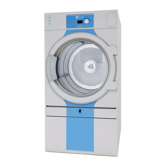
Page 1: Tumble Dryer
Installation manual Tumble dryer T5675 Type N2... 438 9054-20/AU 2014.06.24 Installation manual in original language... - Page 3 DO NOT USE OR STORE FLAMMABLE MATERIALS IN THE APPLIANCE STORAGE DRAWER OR NEAR THIS APPLIANCE. DO NOT SPRAY AEROSOLS IN THE VICINITY OF THIS APPLIANCE WHILE IT IS IN OPERATION. For parts, service and technical assistance please contact: Electrolux Laundry Systems 5–7 Keith Champbell Crt Scoresby Victoria 3179...
- Page 4 Additional safety instructions and warnings To minimize the risk of fire in a tumble dryer, the following should be observed: • Items that have been spotted or soaked with vegetable or cooking oil constitute a fire hazard and should not be placed in a tumble dryer. •...
-
Page 5: Table Of Contents
Contents Contents 1 Safety Precautions ......................7 1.1 Symbols........................8 2 Technical data ........................9 2.1 Drawing ........................9 2.2 Technical data......................10 2.3 Connections........................ 10 2.4 Sound levels ....................... 10 3 Setup..........................11 3.1 Unpacking........................11 3.2 Siting........................... 12 3.3 Mechanical installation .................... -
Page 7: Safety Precautions
Safety Precautions 1 Safety Precautions This appliance can be used by children aged from 8 years and above and persons with reduced physical, sensory or mental capabilities or lack of experience and knowledge if they have been given supervision or instruction concerning use of the appliance in a safe way and understand the hazards involved. -
Page 8: Symbols
Safety Precautions Gas heated tumble dryer: Before installation, check that the local distribution conditions, nature of gas and pressure and the adjustment of the appliance are compatible. The machine is not to be installed in rooms containing cleaning machines with perchloroethylene, TRICHLOROETHYLENE or CHLOROFLUOROCONTAINING HYDROCARBONS as cleaning agents. -
Page 9: Technical Data
Technical data 2 Technical data 2.1 Drawing B(b) B(a) Operating panel Door opening, ⌀ 810 mm Electrical connection Gas connection Exhaust connection Steam: in Steam: out B(a) B(b) 1560 1640 1857 1490 1560... -
Page 10: Technical Data
Technical data 2.2 Technical data Weight, net Drum volume litres Drum diameter Drum depth Drum speed, medium load Rated capacity, filling factor 1:18 (Max. load) 37.5 Rated capacity, filling factor 1:22 (Recommended load) 30.6 Heating: Electricity Heating: Gas Heating: Steam Maximum air flow, Electric 50 Hz / 60 Hz 1140 / 1140 Maximum air flow, Gas 50 Hz / 60 Hz... -
Page 11: Setup
Setup 3 Setup 3.1 Unpacking Note! Two persons are recommended for the unpacking. The machine is delivered complete with supporting feet. The machine is delivered bolted onto the transport pallet and packed in a crate or box. Remove packing from the machine. Remove the bolts between the machine and pallet. -
Page 12: Siting
Setup 3.2 Siting The machine should be positioned so that there is plenty of room for working, both for the user and service personnel. The figure shows minimum distance to a wall and/or other machines. ② Max. 50 mm / 1 15/16 inch Min. -
Page 13: Marine Installation
Marine installation 4 Marine installation To ensure steadiness of the machine it is important to fasten the machine to the foundation. Fasten the four fittings (supplied with the marine machine model) to the foundation using four x M10 set screws. If the four fittings are not supplied, order kit No. 487193544. Fasten the machine to the fittings. -
Page 14: Reversing The Door
Reversing the door 5 Reversing the door Disconnect the power to the machine. Demount the hinges and remove the door. Remove the upper hinge first. ⑤ fig.7166 Remove the screws on the front panel and carefully loosen the panel. Push the door switch cable down through the hole in order to access the cable and then disconnect the cable. - Page 15 Reversing the door Move the door switch cable to the opposite side. Note! The plastic plug MUST be placed in the hole where the door switch cable was before. ⑦ fig.7170 Loosen the nuts and move the two brackets to the opposite side. ⑧...
- Page 16 Reversing the door Move the door switch on the front panel. ⑨ fig.7172 Move the four metal clips from the opposite side. ⑩ fig.7174...
- Page 17 Reversing the door Connect the door switch cable and push the cable in over the drum and pull it upwards. ⑪ fig.7549 Remount the front panel. Ensure that the door switch cable does not get damaged when remounting the front panel. Fasten the hinges and mount the door on the opposite side.
-
Page 18: Evacuation System
Evacuation system 6 Evacuation system 6.1 Air principle The fan creates low pressure in the machine, drawing air into the drum via the heating unit. The heated air passes through the garments and the drum holes. The air then flows outh through a lint filter positioned below the drum. Then the air is evacuated through the fan and exhaust system. -
Page 19: Fresh Air
Evacuation system 6.2 Fresh air For maximum efficiency and the shortest possible drying time, it is important to ensure that fresh air is able to enter the room from the outside in the same volume as that blown out of the room. To avoid draught in the room it is important to place the air inlet behind the machine. -
Page 20: Exhaust Duct
Evacuation system 6.3 Exhaust duct • Only rigid or flexible metal duct should be used for exhausting. • Plastic ducting is not to be used. • Recommended material for exhaust is galvanized steel. • The duct is not to be assembled with screws of other fastening means that extend into the duct and catch lint. -
Page 21: Shared Exhaust Duct
Evacuation system 6.4 Shared exhaust duct It is recommended that each machine is connected to a separate exhaust duct. When several machines shall use the same exhaust duct the exhaust duct must increase after each machine. ⑯ Number of machines Exhaust duct ⌀... -
Page 22: Exhaust Dimensioning
Evacuation system 6.5 Exhaust dimensioning It is important that the machine has correct air volume compared to each machines power. If the air flow is smaller or larger this will result in a longer drying period. The machine is designed to work with the maximum static back pressure according to the table in the technical data section. -
Page 23: Adjusting The Dryer
Evacuation system 6.6 Adjusting the dryer Adjusting the dryer may only be carried out by authorized personnel. The dryer is pre-set for optimal air flow with up to 15 m equivalent pipe length. For longer pipes it is necessary to adjust the dryer according to the following instructions. For default settings from factory, check the label attached on the damper. - Page 24 Model name Heating / Frequency Static pressure Resulting Nominal air flow cold in NTC sensor empty machine (m position (Pa) T5675 1140 Electric / 50 Hz T5675 Electric / 60 Hz 1150 1140 T5675...
- Page 25 Evacuation system Alternative measuring meathod Adjusting the dryer may only be carried out by authorized personnel. Use a home made U tube manometer, a hose (max ⌀ 10 mm), with water. Insert one end of the hose in the hole, hold the hose according to the picture so that the water is in level. Start the machine and measure the difference between the water in one of the hose ends with the other.
-
Page 26: Steam Connection
Steam connection 7 Steam connection 7.1 Connecting the steam Note! The steam pipe must be cut off and must not be under pressure. • The branch pipe’s must be located at the top of the main steam pipe to prevent condensation in the steam. -
Page 27: Steam Calorifier
Steam connection 7.2 Steam calorifier Mount the steam calorifier Unpack the steam calorifier. Demount the back panel on the machine. Demount the supporting rail on the machine (A). Note which way the supporting rail turns as it has to be remounted the same way. ⑳... - Page 28 Steam connection When ready • Leak test the system. • Clean the dirt collectors. • Perform a function chek.
-
Page 29: Gas Connection
Gas connection 8 Gas connection 8.1 General Caution This appliance shall be installed only by authorised personnel and in accordance with the manufacturer’s installation instructions, local gas fitting regulations, municipal building codes, electrical wiring regulations, AS5601/AG601 — Gas Installations and any other statutory regulations. Mount a shut-off valve upstream from the machine. -
Page 30: Table Of Pressure And Adjustment
Gas connection 8.2 Table of pressure and adjustment Total nomi- Inlet Injector Injector size Air reducing Label May be category nal gas con- pressure pressure (⌀ mm) plate (mm) number available sumption (kPa) (kPa) in following (MJ/h) countries Natural 1.13 0.80 4.00 490359201... -
Page 31: Test Run
Gas connection 8.3 Test run • Loosen the measuring branch screw (2) 1/4 turn; connect a manometer to the measuring branch. • Select a program with heat. • Start the machine. • Check the nozzle pressure, see “Table of pressure and adjustment”. •... -
Page 32: Converting Instructions
Gas connection 8.4 Converting instructions • Disconnect the power to the machine. • Demount the lower back panel. • Remove the air reducing plates. • Remove the nozzle (1). • Mount the new supplied nozzle. • Mount the new air reducing plates according to the table. fig.7182 •... - Page 33 Gas connection • Check that the gas flame burns evenly. • Mount the cover screw (3). • Remount the lower back panel.
-
Page 34: Data Label
MANIF. PRESSURE : 0.8 KP A ORF. M. BURNER MM. : 3.50 MM Ø AGA AP P ROVAL NO : ? Electrolux Laundry Systems 5-7 Keith Campbell Crt Scoresby V ictoria 3179 For safety reasons use only genuine spar e par ts. -
Page 35: Electrical Connection
Electrical connection 9 Electrical connection 9.1 Electrical installation The electrical installation may only be carried out by qualified personnel. Machines with frequency-controlled motors can be incompatible with certain types of earth leakage circuit breaker. It is important to know that the machines are designed to provide a high level of personal safety, which is why items of external equipment such as earth leakage circuit breakers are not necessary. -
Page 36: Single-Phase Connection
Electrical connection 9.2 Single-phase connection Demount the cover panel from the supply unit. Connect the earth and other wires as shown. 1NAC L2/N When the installation is completed remount the cover panel and check: • That the drum is empty. •... -
Page 37: Three-Phase Connection
Electrical connection 9.3 Three-phase connection Demount the cover panel from the supply unit. Connect the earth and other wires as shown. 3NAC 3NAC When the installation is completed remount the cover panel and check: • That the drum is empty. •... -
Page 38: Electrical Connections
Electrical connection 9.4 Electrical connections Heating Main voltage Heating power Total power Recommended alternative fuse Electric heated 32.0 34.6 380–415V 3/3N ~ 50/60 380–415V 3/3N ~ 50/60 40.0 42.6 440–480V 3 ~ 32.0 34.7 440–480V 3 ~ 40.0 42.7 230–240V 3 ~ 50/60 32.0 34.4... -
Page 39: Functions For I/O-Cards
Electrical connection 9.5 Functions for I/O-cards The electrical schematic can be one of the following: 9.5.1 Central payment (2J) To start the machine from a central payment system, the payment system must transmit a start pulse 300–3000 ms (500 ms is recommended) with a minimum pause of 300 ms (500 ms is recommended) between two pulses. -
Page 40: Central Payment (2J)
Electrical connection 9.5.2 Central payment (2J) The central payment or booking system shall transmit an active (high) signal to the machine once permission has been granted to start the machine. The signal must remain active (high) during drying. When the signal gets inactive (low) the machine will abort ongoing program and enter cooling. -
Page 41: External Coin Meter/Central Payment (2K)
Electrical connection 9.5.3 External coin meter/Central payment (2K) The signal received from external coin meters must be a pulse between 300–3000 ms (500 ms is recommended) with a minimum pause of 300 ms (500 ms is recommended) between two pulses. fig.7438... -
Page 42: Price Reduction (2K)
Electrical connection 9.5.4 Price reduction (2K) By maintaining an activated (high) signal on connection 5 ("Price red"), the price of the program can be reduced. This function has a number of uses, including providing reductions during a specific period of the day. Whilst the signal remains active (high), the price of the program is reduced (or the time is increased on time programs), by the percentage entered in the price programming menu. -
Page 43: External Connection 100 Ma
Electrical connection 9.6 Option 9.6.1 External connection 100 mA A special connection terminal is located on the connection console. This connection can be used as external control of a fan. The terminal for external control is equipped with 220–240V max.100 mA and is intended solely for the operation of a contactor. -
Page 44: Function Check
Function check 10 Function check May only be carried out by qualified personnel. A function check must be made when the installation is finished and before the machine can be ready to be used. Whenever a repair has been made, a function check must be performed before the machine can be used again. - Page 45 Function check If the direction is wrong, swop two of the three phases to the left on the connection terminal. fig.7119 Check the heat • Let the machine work for five minutes on a program with heat. • Check that the heating is working by opening the door and feel if there is heat in the drum. Ready to use If all tests are OK the machine is now ready to be used.
- Page 48 Electrolux Laundry Systems Sweden AB 341 80 Ljungby, Sweden www.electrolux.com/laundrysystems Share more of our thinking at www.electrolux.com...