Table of Contents
Advertisement
Quick Links
Specifications
lGeneral
Power Source:
Power consumption:
Dimensions (W×H×D):
Mass:
lAmplifier section
RMS Output Power: Dolby Digital Mode
lTotal RMS Dolby Digital
mode Power:
At 1kHz and total harmonic of 10%
lFront:
lCenter:
lSurround:
At 100Hz and total harmonic of 10%
lActive subwoofers:
DIN Output Power: Dolby Digital Mode:
lTotal DIN Dolby Digital mode Power:
At 1kHz and total harmonic of 1%
lFront:
lCenter:
AC 230V, 50Hz
115 W
430×60×354 mm
3.35kg
850 W
110 W/ Channel (3Ω)
225 W/ Channel (6Ω)
90 W/ Channel (4Ω)
225 W/ Channel (6Ω)
440 W
80 W/ Channel (3Ω)
75 W/ Channel (6Ω)
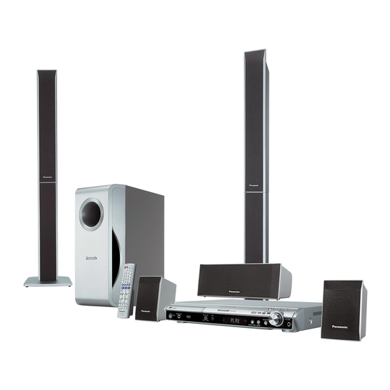
DVD Home Theater Sound System
SA-HT540EE
Colour
(S).......................Silver Type
lSurround:
At 100Hz and total harmonic of 1%
lSubwoofer:
lPreset Memory:
lFM tuner section (FM)
Frequency Range:
Sensitivity:
S/N 26dB
Antenna Terminals:
lAM tuner section (AM/MW)
Frequency Range:
AM Sensitivity S/N 20dB at
999kHz:
lPhone jack:
Terminal:
lMic jack:
Sensitivity:
Terminal:
lFront M. Port:
© 2006 Panasonic AVC Networks Singapore Pte.
Ltd. All rights reserved. Unauthorized copying and
distribution is a violation of law.
ORDER NO.MD0605176C3
65 W/ Channel (4Ω)
75 W/ Channel (6Ω)
FM 15 stations
AM/MW 15 stations
87.5-108.0MHz
(50kHz step)
2.5µV (IHF)
2.2µV
75Ω (unbalanced)
522-1629kHz (9kHz step)
560µV/m
Stereo 3.5 mm jack
0.7mV (1.2kΩ)
Mono 6.3 mm jack (1 system)
Advertisement
Table of Contents

Related Manuals for Panasonic SA-HT540EE


Summary of Contents for Panasonic SA-HT540EE
-
Page 1: Specifications
80 W/ Channel (3Ω) Terminal: Mono 6.3 mm jack (1 system) 75 W/ Channel (6Ω) lFront M. Port: lCenter: © 2006 Panasonic AVC Networks Singapore Pte. Ltd. All rights reserved. Unauthorized copying and distribution is a violation of law. - Page 2 Note: long and narrow pictures may not be displayed. 1. Specifications are subject to change without notice. *4 MPEG4 data recorded with Panasonic SD multi cameras or DVD video recorders. Mass and dimensions are approximate. lConforming to SD VIDEO specifications (ASF standard)/ 2.
- Page 3 SA-HT540EE...
-
Page 4: Table Of Contents
SA-HT540EE CONTENTS Page Page 1 Safety Precautions 10.1. Servicing position of the DVD Module P.C.B. 1.1. GENERAL GUIDELINES 10.2. Servicing position of the Main P.C.B. 1.2. Before Repair and Adjustment 11 Assembly and disassembly of Mechanism Unit 1.3. Protection Circuitry 11.1. - Page 5 SA-HT540EE 25 Replacement Parts List 25.1. Component Parts List...
-
Page 6: Safety Precautions
SA-HT540EE 1 Safety Precautions 1.1. GENERAL GUIDELINES 1. When servicing, observe the original lead dress. If a short circuit is found, replace all parts which have been overheated or damaged by the short circuit. 2. After servicing, see to it that all the protective devices such as insulation barriers, insulation papers shields are properly installed. -
Page 7: Prevention Of Electro Static Discharge (Esd) To Electrostatically Sensitive (Es) Devices
SA-HT540EE If this occurs, follow the procedure outlines below: 1. Turn off the power. 2. Determine the cause of the problem and correct it. 3. Turn on the power once again after one minute. Note: When the protection circuitry functions, the unit will not operate unless the power is first turned off and then on again. -
Page 8: Precaution Of Laser Diode
SA-HT540EE 3 Precaution of Laser Diode CAUTION : This product utilizers a class 1 laser. Invisible laser radiation is emitted from the optical pick up lens. When the unit is turned on: Wavelength : 662nm (DVD) / 785nm (CD) Maximum output radiation power from pick up : 100µW/VDE Laser radiation from pick up unit is safety level, but be sure the followings: 1. -
Page 9: About Lead Free Solder (Pbf)
SA-HT540EE 4 About Lead Free Solder (PbF) 4.1. Service caution based on legal restrictions 4.1.1. General description about Lead Free Solder (PbF) The lead free solder has been used in the mounting process of all electrical components on the printed circuit boards used for this equipment in considering the globally environmental conservation. -
Page 10: Handling Precautions For Traverse Unit
SA-HT540EE 5 Handling Precautions for Traverse Unit The laser diode in the optical pickup unit may break down due to static electricity of clothes or human body. Special care must be taken avoid caution to electrostatic breakdown when servicing and handling the laser diode. - Page 11 SA-HT540EE...
-
Page 12: Accessories
SA-HT540EE 6 Accessories AC cord Remote control AM loop antenna Speaker cable FM indoor antenna Video cable Speaker label Screws... -
Page 13: Operation Procedures
SA-HT540EE 7 Operation Procedures 7.1. Remote Control Key Buttons Operations... -
Page 14: Main Unit Key Buttons Operations (Sa-Ht540)
SA-HT540EE 7.2. Main Unit Key Buttons Operations (SA-HT540) OPEN CLOSE TUNING VOLUME SELECTOR MUSIC PORT AC IN ME MOR Y... -
Page 15: Using Of Music Port
SA-HT540EE 7.3. Using of Music Port MONO... -
Page 16: Disc Information
Recorded with Panasonic SD multi cameras or DVD video recorders using the DCF (Design rule for Camera File System) Standard Version 1.0. Recorded with Panasonic SD multi cameras or DVD video recorders [conforming to SD VIDEO MPEG4 specifications (ASF standard)/MPEG4 (Simple Profile) video system/G.726 audio system]. - Page 17 SA-HT540EE 7.4.2. File Extension Type Support (WMA/JPEG/MP3)
-
Page 18: About Divx Vod Content
SA-HT540EE 7.5. About DivX VOD Content... -
Page 19: Self-Diagnosis And Special Mode Setting
SA-HT540EE 8 Self-Diagnosis and special mode setting 8.1. Service Mode Summary Table The service modes can be activated by pressing various button combination on the player and remote control unit. Below is the summary of major checking: Player buttons Remote control unit buttons... - Page 20 SA-HT540EE 8.2.1. Service Mode Table 1 Item Key Operation FL Display Mode Name Description Front Key Jitter check Jitter check In STOP (no disc) mode, Jitter rate is measured and displayed. press STOP button on the Measurement is repeatedly done in player, and "5"...
- Page 21 SA-HT540EE 8.2.2. Service Mode Table 2 Item Key Operation FL Display Mode Name Description Front Key Micro-processor In STOP (no disc) Micro-processor firmware version firmware version mode, press STOP button display & EEPROM checksum display. display & on the player, and "7"...
- Page 22 SA-HT540EE 8.2.3. Service Mode Table 3 Item Key Operation FL Display Mode Name Description Front Key In STOP (no disc) Timer 1 check Timer 1 check mode, press STOP button Laser operation timer is measured on the player, and "...
- Page 23 SA-HT540EE...
-
Page 24: Dvd Self Diagnostic Function-Error Code
SA-HT540EE 8.3. DVD Self Diagnostic Function-Error Code 8.3.1. Error Code Table 1 Error Diagnosis Contents Description of error Automatic FL Display Remarks Code Focus servo error Focus coil NG (OPU unit abnormal) Press [ n STOP] on main unit for next error. - Page 25 SA-HT540EE 8.3.2. Error Code Table 2 Error Diagnosis Contents Description of error Automatic FL Display Remarks Code F505 DSC Attention error Similar as F500 Press [ n STOP] on main unit for next error F506 Invalid media Disc is flipped over, TOC unreadable,...
-
Page 26: Sales Demonstration Lock Function
SA-HT540EE 8.3.3. Error Code Table 3 Error Diagnosis Contents Description of error Automatic FL Display Remarks Code F702 Message command Message is changed before it is sent as Press [ n STOP] on main changes a reply to disc manager... -
Page 27: Service Precautions
SA-HT540EE “___LOCKED_” appears when the function is activated.) Note: OPEN/CLOSE , DISC CHECK and DISC CHANGE buttons are invalid and the player displays “___LOCKED_” while the lock function mode is entered. · Prohibiting operation of selector and disk 1. Select the DVD/CD function. - Page 28 SA-HT540EE 1. Press on remote control while pressing “STOP” button on main unit. (To enter into initialization) 2. FL display show “INIT” 3. While still pressing “STOP” button on main unit, press “ENTER” on remote control. (To reset the unit) 4.
-
Page 29: Assembling And Disassembling
SA-HT540EE 9 Assembling and Disassembling “ATTENTION SERVICER” Be careful when disassembling and servicing. Some chassis components may have sharp edges. Special Note: 1. This section describes the disassembly procedures for all the major printed circuit boards and main components. 2. Before the disassembly process was carried out, do take special note that all safety precautions are to be carried out. -
Page 30: Disassembly Flow Chart
SA-HT540EE 9.1. Disassembly Flow Chart... -
Page 31: Main Components And P.c.b. Locations
SA-HT540EE 9.2. Main Components and P.C.B. Locations... -
Page 32: Disassembly Of Top Cabinet
SA-HT540EE 9.3. Disassembly of Top Cabinet Step 1 Remove 4 screws. Step 2 Remove 3 screws. (Rear view) Step 3 Lift up and remove the top cabinet. 9.4. Disassembly of the DVD Lid (When taking out disc manually) Step 1 Detach the gear for drawing out tray from the mechanism unit. -
Page 33: Disassembly Of Front Panel Assembly
SA-HT540EE 9.5. Disassembly of Front Panel Assembly · Follow Item 9.3. Step 1 Remove the DVD lid. Step 2 Detach FFC cables at connectors. (CN2006, CN2007 & Step 5 Detach the front panel assembly. CN2017) Special Note: Avoid placing the set in a position that might Step 3 Remove 1 screw. -
Page 34: Disassembly Of Dvd Mechanism Unit
SA-HT540EE Step 6 Remove 6 screws. Step 7 Remove FL P.C.B., Top Button P.C.B. & Mic P.C.B. 9.8. Disassembly of DVD Module P.C.B. · Follow Item 9.7. Step 1 Remove 4 screws. Step 2 Detach FFC cables at the connectors.(FP8251, FP8531) 9.7. -
Page 35: Disassembly Of Scart P.c.b
SA-HT540EE 9.12. Disassembly of Digital Amp IC (IC5000/IC5200/IC5300) · Follow (Step 1) to (Step 2) of Item 9.11. · Disassembly of digital amp IC (IC5000). Step 1 Desolder all the pins of the digital amp IC. Step 2 Release the claws and remove the heat sink clip. -
Page 36: Disassembly Of Switch Regulator Ic (Ic5701)
SA-HT540EE Note: Refer to the diagrams of Main P.C.B. (Section 19.2) for location of the parts. 9.15. Disassembly of Switch Regulator IC (IC5701) · Follow (Step 1) to (Step 2) of Item 9.11. Step 1 Desolder all pins of IC5701. -
Page 37: Service Position
SA-HT540EE 10 Service Position 10.1. Servicing position of the DVD Module P.C.B. · Follow Item 9.7. · Follow (Step 1) of Item 9.8. · Follow (Step 1) to (Step 2) of Item 9.9. Step 1 Connect FFC cables at connectors. (CN2001, CN2004, CN2006, CN2007 &... -
Page 38: Assembly And Disassembly Of Mechanism Unit
SA-HT540EE 11 Assembly and Step 4 Remove the traverse unit. disassembly of Mechanism Unit 11.1. Disassembly Procedure 11.1.2. Disassembly of Tray Unit Step 1 Slide the guide tray unit while pressing the stopper in the arrow direction, and remove the guide tray unit. - Page 39 SA-HT540EE Step 3 Hook the drive arm concave phase over the tray and Step 4 Spread the tabs at the both sides and pull the tray out. the tray slider. (The tray slides a little forword and stops.). Step 4 Press in the tray.
- Page 40 SA-HT540EE Step 7 Turn the change lever in the arrow direction till it stops. Step 8 Hook the change lever spring on the change lever project part temporarily. Step 2 Hook the lock lever spring on the lock lever projection part temporarly.
- Page 41 SA-HT540EE 11.1.4. Disassembly of Tray Loading P.C.B. Step 1 Remove 3 screws Step 2 Remove 4 pins. 11.1.5. Disassembly of Optical Pickup Unit Special Note: Anti-static measures are necessary due to handling of OPU unit . Step 3 Remove the middle chassis.
- Page 42 SA-HT540EE Step 7 Remove 1 screw. Step 8 Slide the shaft in the arrow direction. Step 4 Remove the optical pickup unit in the arrow direction till it stops. Step 9 Lift the optical pickup unit with the shaft. Step 5 Remove 2 screws.
- Page 43 SA-HT540EE (Assembling the optical pickup unit) Step 1 Pass the intermediate FPC through the frame hole. Step 2 Align the guide section of the optical pickup unit with the rail. Step 3 Install the shaft top to the holder. Step 11 Pull the shaft and the rubber out.
-
Page 44: Measurements And Adjustments
SA-HT540EE 12 Measurements and Adjustments 12.1. Service Tools and Equipment Application Name Number Tilt adjustment DVD test disc DVDT-S20 [SPG] TORX screw driver (T6) Available on sales route. (T6) or RFKZ0185 [SPG] Others Grease RFKXPG641 [SPG] Confirmation CD test disc... -
Page 45: Optical Adjustment
SA-HT540EE 12.4. Optical adjustment 12.4.1. Optical pickup tilt adjustment Measurement point Adjustment point Mode Disc Tangential adjustment screw T01 (inner periphery) play DVDT-S20 [SPG] Tilt adjustment screw T30 (center periphery) T43 (outer periphery) play Measuring equipment Adjustment value None (Main unit display for servicing is used.) Adjust to the minimum jitter value. -
Page 46: Abbreviations
SA-HT540EE 13 Abbreviations INITIAL/LOGO ABBREVIATIONS ERROR TORQUE CONTROL ERROR TORQUE CONTROL INITIAL/LOGO ABBREVIATIONS REFERENCE A0~UP ADDRESS ENCSEL ENCODER SELECT ACLK AUDIO CLOCK ETMCLK EXTERNAL M CLOCK (81MHz/40.5MHz) AD0~UP ADDRESS BUS ETSCLK EXTERNAL S CLOCK (54MHz) ADATA AUDIO PES PACKET DATA... - Page 47 SA-HT540EE INITIAL/LOGO ABBREVIATIONS INITIAL/LOGO ABBREVIATIONS READ ENABLE VBLANK V BLANKING RFENV RF ENVELOPE COLLECTOR POWER SUPPLY RF PHASE DIFFERENCE OUTPUT VOLTAGE (CD-ROM) REGISTER SELECT VCDCONT VIDEO CD CONTROL (TRACKING RSEL RF POLARITY SELECT BALANCE) RESET DRAIN POWER SUPPLY VOLTAGE RESERVE...
-
Page 48: Voltage And Waveform Chart
SA-HT540EE 14 Voltage and Waveform Chart 14.1. DVD Module P.C.B. IC8001 Re f No. MODE CD P LAY IC8001 Re f No. MODE CD P LAY IC8001 Re f No. MODE CD P LAY IC8001 Re f No. MODE CD P LAY Re f No. -
Page 49: Main P.c.b
SA-HT540EE 14.2. Main P.C.B. Re f No. IC2004 MODE CD P LAY S TANDBY IC2018 Re f No. MODE CD P LAY S TANDBY IC2018 Re f No. MODE CD P LAY S TANDBY IC2018 Re f No. MODE CD P LAY... - Page 50 SA-HT540EE IC5000 Re f No. MODE CD P LAY 29.2 -29.2 -21.2 29.5 -3.4 -29.4 -16.8 -29.2 -3.4 29.5 -29.2 -29.2 29.2 S TANDBY 29.2 -29.2 -21.2 29.2 -3.4 -29.4 -16.8 -29.4 -3.4 29.5 -29.2 -29.2 29.2 IC5000 Re f No.
-
Page 51: Fl P.c.b., Scart P.c.b., Mic P.c.b. & Tray Loading P.c.b
SA-HT540EE 14.3. FL P.C.B., Scart P.C.B., Mic P.C.B. & Tray Loading P.C.B. FL P .C.B. IC6901 Re f No. MODE CD P LAY -0.1 -21.0 -21.0 -18.9 -18.8 -14.7 -18.9 -14.7 S TANDBY -21.0 -21.0 -21.0 -18.9 -10.5 -8.4 -14.7 IC6901 Re f No. -
Page 52: Waveform Chart
SA-HT540EE 14.4. Waveform Chart WF No. IC2018-13 (PLAY) WF No. IC2102-20 (PLAY) WF No. IC2102-30 (PLAY) WF No. IC2103-7 (PLAY) 5.4Vp-p(100nsec/div) 0.1Vp-p(500usec/div) 4.4Vp-p(5msec/div) 1.2Vp-p(2usec/div) WF No. IC2801-4 (PLAY) WF No. IC2801-8 (PLAY) WF No. IC2801-11 (PLAY) WF No. IC2801-13 (PLAY) 0.7Vp-p(2msec/div) -
Page 53: Illustration Of Ic's, Transistors And Diodes
SA-HT540EE 15 Illustration of IC's, Transistors and Diodes RFKWMHA0B160 C3EBEG000073 (8p) C0ABBB000230 (8p) C0HBB0000057 (44p) C1BB00001098 (100p) C0CBCBD00018 (8p) C3EBGC000055(8p) C2CBYY000195 (100p) C3ABPG000145 (54p) C0EBA0000029 (4p) MN2DS0009AP (256p) C9ZB00000461 (132p) C0FBBK000050 (28p) No.1 MN864701 (164p) C0JBAB000011 (14p) No.1 C0GBG0000048 C0DAAMH00012... - Page 54 SA-HT540EE...
-
Page 55: Wiring Connection Diagram
TO TUNER PACK UNIT FP8101 CP2010 LOADING MOTOR MIC P.C.B. CS901 (SOLDER SIDE) TUNER EXTENT P.C.B. TRAY LOADING P.C.B. DVD MODULE P.C.B. H6903 DVD MODULE P.C.B. (SIDE:B) (SOLDER SIDE) (SOLDER SIDE) (SIDE:A) JK6802 VR6081 CN2010 MIC LEVEL SA-HT540EE WIRING CONNECTION... - Page 56 SA-HT540EE...
-
Page 57: Block Diagram
ACT T+ LEVEL VOL1- ACT T- SHIFT RFINN FOCUS RFINP COIL ACT F+ ACT F- SPMUTE MUTE3 DRV4 MUTE VOL2+ TRVFT MUTE MUTE12 CH1,2 LEVEL VOL2- DRV3 MUTE SHIFT MUTE4 MUTE QR8571 BUFFER TRAVERSE INNER SW DRV2 SA-HT540EE BLOCK DIAGRAM... - Page 58 AND GATE DVD CLK OP CPU CLK NEXOE NEXWE NEXCE OP CPU CMD DVD CMD EXDT0 IC8695 C0JBAA000346 AND GATE DVD STAT OP CPU STAT DATA IC8601 C0EBA0000029 RESET IC8611 NRST EEPROM IC8606 EXDT15 C0EBE0000455 RESET (Not Supplied) SA-HT540EE BLOCK DIAGRAM...
- Page 59 Q2006 POWER ON ZFLAG RESET MUTING DVD MUTE DVD CLK DVD CLK DVD CMD IC2018 DVD CMD DVD STAT DVD STAT C2CBYY000195 ST/DO TUN DO SYSTEM CONTROL TUN DI TUN SD POWER TUN CLK SUPPLY (FM:ON) (FM) SA-HT540EE BLOCK DIAGRAM...
- Page 60 INVERTER (CLOCK GENERATOR) IC2204 C0ABBB000230 IC2600 MIC AMP C0ABBB000230 VR6081 SUBWOOFER PHASE INVERTER JK6802 X5500 Q5500 375KHz SWITCH X5501 Q5501 415KHz SWITCH D6900 Q2004 Z6900 VR6800 (REMOTE SENSOR) (VOLUME) DRIVE Q2003 VREF+ X2001 RESET 10MHz IC2018 C2CBYY000195 SYSTEM CONTROL SA-HT540EE BLOCK DIAGRAM...
- Page 61 SURROUND R+ CONTROL CONTROL SUBWOOFER + OUT2 IN2P SWITCH2 OUT2 SURROUND R IN2P SWITCH2 HANDSHAKE INPUT HANDSHAKE INPUT DRIVER DRIVER STAGE RELEASE2 STAGE RELEASE2 MODULATOR Q5601-5604 MODULATOR IN2M IN2M MODE 1 MUTING MODE 2 IC2018 C2CBYY000195 SYSTEM CONTROL SA-HT540EE BLOCK DIAGRAM...
- Page 62 C0GAY0000013 Q2915 MOTOR DRIVE(LOADING) DETECT LOADING V REF MOTOR IC2004 DRIVE CONTROL EEPROM (Not Supplied) KEY SWITCH KEY SWITCH FL00 (S6801-6805) (S6806) IC6901 X OUT C0HBB0000057 DISPLAY DRIVER X IN S902 S901 IC2018 C2CBYY000195 SYSTEM CONTROL AVSS SA-HT540EE BLOCK DIAGRAM...
- Page 63 C0CBCBD00018 +3.3V DC-DC REGULATOR CONVERTER Q2914, D2944 IC5701 C5HABZZ00125 +2.7V Q5701 SWITCHING REGULATOR REGULATOR Q5747 D5748,49 CONT CURRENT SWITCHING LIMMITTING QR8111 SWITCH POWER CONTROL D5741 DRAIN IC8151 PC5701 C0DBEHG00006 FEED BACK FEED BACK +1.2V REGULATOR Q5710 SWITCHING SA-HT540EE BLOCK DIAGRAM...
- Page 64 SA-HT540EE...
-
Page 65: Schematic Notes
SA-HT540EE 18 Schematic Notes · This schematic diagram may be modified at any time with the development of new technology. Notes: S901: Play detection switch. S902: Open detection switch. S6800: Tray open / close switch ( Open / Close). S6804: F. - Page 66 SA-HT540EE...
-
Page 67: Schematic Diagram
100P LDGND LB8561 J0JBC0000042 LDDVD LB8551 J0JBC0000042 GND(OEIC) C8533 VREF1 LB8531 ERJ2GE0R00X VREFH SUB2 RX8533 VIN6 (56 x 2) SUB1 VIN5 LPC2 PIN(CD) R8532 2.2K RAM_CD SUBSEL R8533 GND(VRCD) W2551 C8532 220P SA-HT540EE DVD MODULE (DV3.2)/ OPTICAL PICKUP UNIT CIRCUIT... - Page 68 AND GATE LOGIC IC C8691 LB8691 ERJ2GEJ101X R8557 C8553 C8551 6.3V47 R8556 C8552 C8554 R8558 R8553 OP_CPU_STAT 16V10 R8555 R8554 R8559 Q8552 C8695 B1ADGB000008 Q8551 R8551 SWITCH LB8692 ERJ2GEJ101X 2SD1819A0L LPC01 SWITCH LB8693 R8552 ERJ2GEJ101X OP_CPU_CMD SA-HT540EE DVD MODULE (DV3.2) CIRCUIT...
- Page 69 C8055 EXADR12 EXADR11 EXADR10 EXADR9 EXADR8 IC8051 C8022 C3ABPG000145 C8606 EXADR19 64MB SDRAM NEXWE EXADR18 EXADR17 R8601 100K EXADR7 C8601 EXADR6 EXADR5 EXADR4 EXADR3 EXADR2 EXADR1 IC8606 C0EBE0000455 RESET IC8601 C8008 C0EBA0000029 RESET C8602 0.015 SA-HT540EE DVD MODULE (DV3.2) CIRCUIT...
- Page 70 VIN5 EXADT3 VIN5 VIN5 EXADT2 VIN9 C8211 VIN6 1200P EXADT1 VIN10 D8211 MA2J11000L L8201 G1C100K00019 D+3.3V 65 66 67 68 69 70 71 72 73 L8501 G1C100K00019 C8528 C8529 R8003 C8201 C8501 6.3V100 6.3V100 C8505 SA-HT540EE DVD MODULE (DV3.2) CIRCUIT...
-
Page 71: Bmain Circuit
W2555 J0JBC0000015 R2816 75 C2827 C2826 Q2805 100P 100P WIDE W2550 B1GBCFJN0033 C2833 INVERTER 330P L2806 COUT J0JBC0000015 R2817 75 W2610 W2540 W2546 C2840 L2807 6.3V1000 J0JBC0000015 R2818 75 W2542 YOUT C2831 C2830 C2832 100P 330P 1000P SA-HT540EE MAIN CIRCUIT... - Page 72 R2092 W2508 R2033 RF_DET BRAKE_H RF_DET 5 6 7 8 9 RESET D2005 L2008 B0ACCK000005 G0C3R3JA0027 R2032 W2517 R2026 R2019 C2006 R2001 100K 50V4.7 Q2003 R2095 4.7K B1GBCFLL0037 RESET D2008 R2017 B0ACCK000005 W2509 X2001 H2B100500004 10MHz W2529 SA-HT540EE MAIN CIRCUIT...
- Page 73 MIXL C2301 INL1 SLSELOUT MICIN SLVOLIN AGND SLNFIN C2295 1 LINEOUT-R R2301 RECOUTR SLVOLOUT 100K LINEOUT-L RECOUTL SLFIN C2303 C2302 C2195 1 0.047 0.039 5 6 7 8 9 C2502 0.047 R2503 C2503 0.039 R2303 C2196 470P SA-HT540EE MAIN CIRCUIT...
- Page 74 R2270 HEADPHONE AMP 2.2K C2294 C2278 C2279 R2170 560P 100P 2.2K C2270 R2268 C2277 R2275 R2276 R2277 R2279 R2293 2.2K 5.6K FRVOLOUT HP-RCH FRFIN R2278 R2280 R2288 3.9K SCART_MUTE_S Q1009 B1GDCFGA0018 MUTING CONTROL R1021 SCART_MUTE W2 0 SA-HT540EE MAIN CIRCUIT...
- Page 75 G0A101G00022 VGND -30V FP2000 L2909 R2975 4.7 SCART CIRCUIT G0A200D00002 GNDE (CN1001) ON DC_18V DC_DET SCHEMATIC GNDE SCART_MUTE_S SCARTMUTE DIAGRAM-16 SYS6V SYS6V SYNC SYNC YC_H YC_H GNDE LINEOUT-R ROUT TV-RCH AGND R2935 TV-LCH 4.7K DVD_PCONT LINEOUT-L LOUT SA-HT540EE MAIN CIRCUIT...
-
Page 76: C) Power & Ac-Inlet Circuit
DC_DET L5000 L5002 R5011 ETQA15A150T G0B9R5K00001 Q5102 R5610 B1ABCF000176 8.2K Q5603 DC DETECT B1ADCE000012 Q5101 R5611 MUTING 8.2K D_AMP+5V B1ABCF000176 DC DETECT Q5601 Q5602 B1ABCF000176 B1ABCF000176 R5021 MUTING MUTING SIGNAL R5022 R5602 MOD_DA Q5604 B1ABCF000176 MUTING SA-HT540EE POWER(DIGITAL AMP) CIRCUIT... - Page 77 VDDP SURROUND L+ CENTER- L5400 L5402 SUBWOOFER- SPEAKERS ETQA15A150T G0B9R5K00001 FRONT R- SURROUND R+ FRONT L- FRONT R+ C5310 CENTER+ VSSP R5310 SUBWOOFER+ L5300 L5301 ETQA15A150T G0B9R5K00001 C5327 0.1 R5300 C5301 R5319 R5035 R5034 5.6K 5.6K SA-HT540EE POWER(DIGITAL AMP) CIRCUIT...
- Page 78 W2620 0 Q5710 DC_13V AM_BP DC_18V 2SC3940ARA DC_18V MGND GNDE SWITCHING DC_GND GNDE IC5702 C0DABFC00002 SHUNT REGULATOR DC_DET DC_DET -30V_M -30V_M C5720 R5715 Q5706 B1BACD000018 REGULATOR D5713 B0BC4R0A0006 D5903 D5923 R5918 R5917 B0BC01200019 B0BC01200019 C5715 10V100 C5916 50V100 SA-HT540EE POWER(SMPS) CIRCUIT...
- Page 79 C5732 50V56 C5709 IC5721 470P C5757 2200P C0DABYY00002 SWITCHING REGULATOR R5726 R5704 Q5704 0.68 B1ABCF000176 CURRENT LIMITTING SWITCH C5729 50V22 PC5721 Q5745 R5727 B3PBA0000402 2.2K B3PBA0000402 FEED BACK Q5746 B1GBCFLL0037 R5779 W5714 INVERTER SYS6V_S D5745 B0EAKM000117 SA-HT540EE POWER(SMPS)/ AC-INLET CIRCUIT...
-
Page 80: D) Fl, Top Button, Tray Loading, Tuner Extent, Mic, Music Port & Scart Circuit
2.7K J0JBC0000019 DIAGRAM- 9 FLGND FLD_CLK FLD_OUT TOP BUTTON CIRCUIT FLD_STB W6988 SW5V R6925 R6926 R6927 1.2K W6938 W6956 W6949 H6901 H6902 W6985 KEY2 KEY2 KEY2 DGND DGND KEY2STOP KEY2STOP KEY2STOP W6974 W6983 W6972 W6973 SA-HT540EE FL/ TOP BUTTON CIRCUIT... - Page 81 D6900 DGND CIRCUIT B3AAA0000803 (CN2006) on L6083 W6901 STBLED W601 J0JBC0000019 JK6802 SCHEMATIC VREF VR6081 W6904 DIAGRAM- 9 W6910 W6906 W6999 EVUE27FK3B53 SW5V L6081 W602 MIC LEVEL J0JBC0000019 W6702 C6701 R6701 L6082 R6081 J0JBC0000030 SA-HT540EE TUNER EXTENT/MUSIC PORT/TRAY LOADING/MIC CIRCUIT...
- Page 82 WIDE RGB_S YC_S R_OUT VGND VGND R1200 R1203 MAIN CIRCUIT RCH_OUT (CN2008) on SCHEMATIC R1201 Q1200 DIAGRAM-9 SCART_MUTE 2SD0601AHL W1101 W1103 MUTING YC_H YC_S ROUT R1101 Q1100 TV_R 2SD0601AHL AGND MUTING TV_L R1100 W1104 R1103 LOUT LCH_OUT SA-HT540EE SCART CIRCUIT...
-
Page 83: Printed Circuit Board
C8013 C8016 LB8693 C8015 R8011 RX8017 RX8012 RX8016 LB8692 RX8018 RX8015 RX8014 RX8011 RX8019 C8057 C8421 C8427 C8422 QR8420 C8424 IC8421 C8428 C8426 FP8251 (TO SPINDLE/ TRAVERSE MOTOR) 3118A 3118A 3118A 3118A (SIDE A) (SIDE B) SA-HT540EE DVD MODULE P.C.B. -
Page 84: B) Main/Power
1 2 3 4 5 6 7 Q2804 W2121 W2545 D2935 CN2002 Q2805 C2026 W2258 W2122 C2022 L2807 R2803 C2829 L2111 D2936 C2812 W2102 R2818 C2801 L2211 W2124 W2547 C2817 C2810 W2510 C2818 Q2801 W2259 CN2004 0475A-3 0475A-3 SA-HT540EE MAIN/POWER P.C.B. -
Page 85: C) Tuner Extent, Ac-Inlet, Tray Loading, Music Port, Top Button, Fl, Mic & Scart
Q1004 L1005 R1005 R1204 R1202 R1103 C1021 R1203 SENSOR MUSIC C1004 Q1005 PORT R1020 R1019 AV OUT TOP BUTTON P.C.B. (REPX0512A) S6804 S6805 S6800 (FORWARD) (REVERSE) (OPEN/CLOSE) 0479A-2 0479A-2 R6926 R6927 R6925 H6902 SA-HT540EE TUNER EXTENT/AC-INLET/FL/MUSIC PORT/TOP BUTTON/TRAY LOADING/MIC/SCART P.C.B. - Page 86 SA-HT540EE...
-
Page 87: Basic Troubleshooting Guide
SA-HT540EE 21 Basic Troubleshooting Guide 21.1. Basic Troubleshooting Guide for Traverse Unit (DVD Module P.C.B.) Problems Checking Points Checking components 1) Distorted picture or abnormal a) Check SDRAM address, data bus, CLK and IC8051 sound is heard during initialisation other control signals waveform... -
Page 88: Overall Block (Ht540)
SA-HT540EE 22 Overall Block (HT540) -
Page 89: Ht540 Dvd Unit Block
SA-HT540EE 22.1. HT540 DVD Unit Block... -
Page 90: Ht540 Block (Analog Signal : Dvd 5.1Ch Play Back Mode)
SA-HT540EE 22.2. HT540 Block (Analog Signal : DVD 5.1ch Play Back Mode) -
Page 91: Ht540 Block (Analog Signal : 2Ch Analog Input Mode)
SA-HT540EE 22.3. HT540 Block (Analog Signal : 2ch Analog Input Mode) -
Page 92: Ht540 Power Supply Block
SA-HT540EE 22.4. HT540 Power Supply Block... -
Page 93: Ht540 Power Block (Smps)
SA-HT540EE 22.5. HT540 Power Block (SMPS) -
Page 94: Terminal Function Of Ics
SA-HT540EE 23 Terminal Function of ICs 23.1. IC2018 (C2CBYY000195): Terminal Name Function Micro processor IC 49 N.C No connection 50 N.C No connection Terminal Name Function 51 N.C No connection 52 N.C No connection 1 TRAY_ Loading mechanism close SW ( L: SW 53 N.C... -
Page 95: Exploded Views
SA-HT540EE 24 Exploded Views 24.1. Cabinet Parts Location... - Page 96 SA-HT540EE...
-
Page 97: Packaging
SA-HT540EE 24.2. Packaging... -
Page 98: Replacement Parts List
SA-HT540EE 25 Replacement Parts List Notes: *Important safety notice: Components identified by mark have special characteristics important for safety purpose. Furthermore, special parts which have purposes of fire-retardant (resistors), high-quality sound (capacitors), low-noise (resistors), etc. are used. When replacing any of components, be sure to use only manufacture’s specified parts shown in the parts list. -
Page 99: Component Parts List
SA-HT540EE 25.1. Component Parts List Ref. Part No. Part Name & Description Remarks RMR1468-K CLAMP PLATE Ref. Part No. Part Name & Description Remarks RAE2018W-S DT69U3 BLOCK RMG0598-A FLOATING RUBBER CABINET AND CHASSIS RMG0617-H CUSHION RUBBER A RMG0618-H CUSHION RUBBER B... - Page 100 SA-HT540EE Ref. Part No. Part Name & Description Remarks Ref. Part No. Part Name & Description Remarks Q1007 2SB0709AHL TRANSISTOR D2918 B0ACCK000005 DIODE Q1009 B1GDCFGA0018 TRANSISTOR D2919 B0ADCJ000020 DIODE Q1100 2SD0601AHL TRANSISTOR D2921 B0ACCK000005 DIODE Q1200 2SD0601AHL TRANSISTOR D2923 B0ACCK000005...
- Page 101 SA-HT540EE Ref. Part No. Part Name & Description Remarks Ref. Part No. Part Name & Description Remarks LB8426 ERJ2GE0R00X CHIP RESISTOR L2211 ERJ3GEY0R00V CHIP JUMPER LB8427 ERJ2GE0R00X CHIP RESISTOR L2801 G0C220JA0055 COIL LB8428 ERJ2GE0R00X CHIP RESISTOR L2802 J0JBC0000015 CHIP INDUCTOR...
- Page 102 SA-HT540EE Ref. Part No. Part Name & Description Remarks Ref. Part No. Part Name & Description Remarks FUSE R1104 ERJ3GEYJ103V 10K 1/16W R1200 ERJ3GEYJ471V 470 1/16W K5D402BNA005 FUSE R1201 ERJ3GEYJ821V 820 1/16W R1202 ERJ3GEYJ104V 100K 1/16W FUSE PROTECTOR R1203 ERJ3GEYJ221V...
- Page 103 SA-HT540EE Ref. Part No. Part Name & Description Remarks Ref. Part No. Part Name & Description Remarks R2081 ERJ3GEYJ103V 10K 1/16W R2300 ERJ3GEYJ183V 18K 1/16W R2083 ERJ3GEYJ221V 220 1/16W R2301 ERJ3GEYJ563V 56K 1/16W R2084 ERJ3GEYJ473V 47K 1/16W R2302 ERJ3GEYJ333V 33K 1/16W...
- Page 104 SA-HT540EE Ref. Part No. Part Name & Description Remarks Ref. Part No. Part Name & Description Remarks R2919 ERJ3GEYJ102V 1K 1/16W R5305 ERJ8GEYJ100V 10 1/8W R2920 ERJ3GEYJ472V 4.7K 1/16W R5306 ERJ3GEYJ562V 5.6K 1/16W R2921 ERJ3GEYJ331V 330 1/16W R5307 ERJ3GEYJ562V 5.6K 1/16W...
- Page 105 SA-HT540EE Ref. Part No. Part Name & Description Remarks Ref. Part No. Part Name & Description Remarks R5766 ERG1SJ220E 22 1W R8261 ERJ2GEJ823X 82K 2W R5767 ERJ3GEYJ102V 1K 1/16W R8262 ERJ2GEJ153X 15K 2W R5768 ERJ3GEYJ222V 2.2K 1/16W R8263 ERJ2GEJ823X 82K 2W...
- Page 106 SA-HT540EE Ref. Part No. Part Name & Description Remarks Ref. Part No. Part Name & Description Remarks W602 ERJ3GEY0R00V CHIP JUMPER W6904 ERJ6GEY0R00V CHIP RESISTOR W1008 ERJ3GEY0R00V CHIP JUMPER W6905 ERJ3GEY0R00V CHIP JUMPER W1101 ERJ3GEY0R00V CHIP JUMPER W6906 ERJ6GEY0R00V CHIP RESISTOR...
- Page 107 SA-HT540EE Ref. Part No. Part Name & Description Remarks Ref. Part No. Part Name & Description Remarks W6978 ERJ3GEY0R00V CHIP JUMPER C2018 ECA1CM331B 330 16V W6979 ERJ6GEY0R00V CHIP RESISTOR C2019 ECA1CM331B 330 16V W6980 ERJ6GEY0R00V CHIP RESISTOR C2020 ECJ1VB1H103K 0.01 50V...
- Page 108 SA-HT540EE Ref. Part No. Part Name & Description Remarks Ref. Part No. Part Name & Description Remarks C2306 ECJ1VB1A154K 0.15 10V C2833 ECJ1VB1H331K 330P 50V C2307 ECJ1VB0J105K 1 6.3V C2840 ECA0JM102B 1000 6.3V C2308 ECJ1VB1A105K 1 10V C2841 ECA0JM102B 1000 6.3V...
- Page 109 SA-HT540EE Ref. Part No. Part Name & Description Remarks Ref. Part No. Part Name & Description Remarks C5040 ECA2AM220B 22 100V C5331 ECJ1VB1H103K 0.01 50V C5106 ECJ1VB1H104K 0.1 50V C5332 ECJ1VB1H103K 0.01 50V C5107 ECJ1VB1H104K 0.1 50V C5340 ECA2AM220B 22 100V...
- Page 110 SA-HT540EE Ref. Part No. Part Name & Description Remarks Ref. Part No. Part Name & Description Remarks C5732 ECJ1VB1H104K 0.1 50V C8013 ECJ0EF1C104Z 0.1 16V C5733 ECA1CM221B 220 16V C8014 ECJ0EF1C104Z 0.1 16V C5736 F1BAF1020020 1000P C8015 ECJ0EF1C104Z 0.1 16V...
- Page 111 SA-HT540EE Ref. Part No. Part Name & Description Remarks C8515 ECJ0EB1A104K 0.1 10V C8516 ECJ0EB1A104K 0.1 10V C8521 ECJ0EB1A104K 0.1 10V C8522 ECJ0EB1A104K 0.1 10V C8523 ECJ0EF1C104Z 0.1 16V C8524 ECJ0EF1C104Z 0.1 16V C8525 ECJ0EB1C562K 5600P 16V C8526 ECJ0EB1C183K 0.018 16V...