Panasonic KX-T206E Installation Manual
Electronic modular switching system
Hide thumbs
Also See for KX-T206E:
- User manual (24 pages) ,
- Product description (20 pages) ,
- User manual (16 pages)

Related Manuals for Panasonic KX-T206E


Summary of Contents for Panasonic KX-T206E
- Page 1 Electronic Modular Switching System Please read this manual before connecting the Electronic Modular Switching System. MODEL KX-T206E...
- Page 2 Thank you for purchasing the Panasonic Model KX-T206E, Electronic Modular Switching System. Service Unit Telephone Optional Equipment Notes • In this Installation Manual, the suffix “E” of each model number is omitted. • A proprietary telephone is abbreviated as “PT”.
-
Page 3: Important Information
If you lose the fuse cover the plug must not be used until a replacement cover is obtained. A replacement fuse cover can be purchased from your local Panasonic Dealer. IF THE FITTED MOULDED PLUG IS UNSUITABLE FOR THE SOCKET OUTLET IN YOUR HOME THEN THE FUSE SHOULD BE REMOVED AND THE PLUG CUT OFF AND DISPOSED OF SAFELY. - Page 4 Important Information This equipment should be used on PSTN lines requiring 2-wire Loop calling unguarded clearing with Loop Disconnect or DTMF address signalling. The equipment must be connected to direct extension lines and a payphone should not be connected as an extension. Operation in Power Failure In the event of a power failure, CO2 is connected to extension 22 automatically.
- Page 5 • Keep the unit away from heating appliances and electrical noise generating devices such as fluorescent lamps, motors and television. These noise sources can interfere with the perform- ance of the Electronic Modular Switching System. • This unit should be kept free of dust, moisture, high temperature (more than 40˚C/104˚F) and vibration, and should not be exposed to direct sunlight.
-
Page 6: Table Of Contents
Specifications ... 7 Before Installation... 8 Unpacking ... 9 Name and Location ... 9 Wall Mounting ... 10 Opening Front Cover... 10 Frame Ground Connection ... 10 System Connection Diagram ... 11 CO Line Connection ... 12 Extension Connection ... 13 Paralleled Telephone Connection ... -
Page 7: Specifications
General Descriptions 1. Capacity ... CO line 2. Control Method ... Stored Program CPU: 8 bits CPU 3. Switching Method ... Space Division CMOS Crosspoint Switch 4. Power Supplies ... Primary 5. Dialling 6. Connector ... CO 7. EXT Connection ... Cable 8. -
Page 8: Before Installation
Please read the following notes concerning installation and connection before installing the system. Safety Installation Instructions When installing telephone wiring, basic safety precautions should always be followed to reduce the risk of fire, electric shock and injury to persons, including the following: 1. -
Page 9: Unpacking
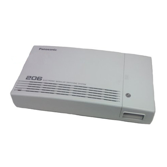
• Main Unit ... one • AC Cord ... one Overview of the Main Unit AC Inlet Inside View of the Main Unit Notes • Doorphone Jack and Door Opener Connector are at SELV. • CO Line 4-pin Jack and Extension 4-pin Jacks are at TNV. Unpacking •... -
Page 10: Wall Mounting
1. Place the templet (on page 39) on the wall to mark the three screw positions. 2. Install the three screws and washers (included) into the wall. 3. Hook the main unit on the screw heads. screw Frame Ground Connection Wall Mounting Opening Front Cover 1. -
Page 11: System Connection Diagram
System Connection Diagram 6 Extensions (one pair) Single Line Telephone (one pair) Cordless Phone (one pair) Telephone Answering Machine with Facsimile to CO1 and CO2 2 CO Lines Doorphone KX-T30865 Door Opener Doorphone KX-T7050 (two pair) (two pair) KX-T7130 (two pair) KX-T7020... -
Page 12: Co Line Connection
Wire Specification Connection Use a 4-pin plug (included) to connect CO lines. A single plug is able to connect two CO lines. Use twisted pair cable. 1. Lift the transparent part. 2. Insert the required telephone wires into the holes of the plug. Then press the transparent part back into the black part. -
Page 13: Extension Connection
Wire Specification Connection Use a 4-pin plug (included) to connect extension lines. There are 6 plugs to connect extensions to EXTN. 1 through EXTN. 6 jacks. 1. Lift the transparent part. 2. Insert the required telephone wires into the holes of the plug. Then press the transparent part back into the black part. -
Page 14: Paralleled Telephone Connection
Paralleled Telephone Connection Any single line telephone can be connected in parallel with a proprietary telephone. 4-conductor wiring cord Connect pins “H”, “A”, “B”, and “L”. Secondary socket Notes • The following features are not available for SLT connected in parallel: Call Splitting External Feature Access Conference... -
Page 15: Installation Of Optional Card And Unit
Installation of Optional Card and Unit Doorphone (KX-T30865) Connection SYSTEM Notes • The doorphone adaptor is not required for KX-T206. • To avoid howling, you must assign all extensions as “DISABLE” in the “#06/#76 Doorphone Assignment (Day/Night)” program when you do not connect a doorphone. •... - Page 16 Installation of Optional Card and Unit DISA Card (KX-T20691) Connection 1. Disconnect the AC cord from the system. 2. Loosen the screws and remove the cover. The DISA feature allows an outside caller to have direct access to intercom calls. System pro- gramming is required.
-
Page 17: Installation Of Lightning Protectors
Installation of Lightning Protectors Overview A lightning protector is a device to be installed on a CO line to prevent a dangerous surge from entering the building and damaging equipment. A dangerous surge can occur if a telephone line comes in contact with a power line. Trouble due to lightning surges have been showing a steady increase with the development of electronic equipment. - Page 18 Installation of Lightning Protectors Outside Notice If you install an extension outside of the main building, the following precautions are recom- mended: (1) Install the extension wire underground. (2) Use a conduit to protect the wire. Note • The lightning protector for an extension is different from that for CO. Installation of an Earth Rod Lightning Protector...
-
Page 19: Power Failure Transfer
Power Failure Transfer In the event of a power failure, CO2 is connected to extension 22 automatically. Note • The system programmed data is protected by the factory provided lithium battery. Starting the System Plug the AC power cord into the system and an AC outlet. •... -
Page 20: General Programming Instructions
System programming can only be performed from extension 21. Use KX-T7130. When you check the assignment, set the MEMORY switch on PT to “PROGRAM”. Enter “#” and the program address. You cannot check programs #60, #62, #63, #65, #67, #84 and #85, as they are not displayed on the display panel. -
Page 21: System Programming
System Speed Dialling Number Set Description Used to program System Speed Dial numbers. These numbers are available to all exten- sion users. There are 40 numbers from 00 through 39. Condition • A maximum of 32 digit numbers can be stored. •... -
Page 22: Outgoing Permitted Co2 Assignment (Day/Night)
Outgoing Permitted CO2 Assignment (Day/Night) Description Determines the extensions which can have access to CO line 2 in both day and night modes. The extension users can make outgoing CO calls if their extensions are assigned as “ENABLE”. Input Format Explanation •... -
Page 23: Doorphone Assignment (Day/Night)
Doorphone Assignment (Day/Night) Description Assigns the extensions which will ring when a doorphone call is received and enables to call the doorphone in both day and night modes. Condition • All extensions must be assigned as “0: DISABLE”, if you do not connect a doorphone to the system. -
Page 24: Trs Denied Code (Class 2, 3)
Description Allows you to specify the numbers which are toll-restricted for TRS Class 2 and Class 3. Condition • The character “ ” can be any number. Input Format Explanation • [A]= Code No.: 0 through 9 1 digit Default All codes–... -
Page 25: Ogm Play
Description Confirms the outgoing message recorded in the OGM Recording program. Condition • If you perform programming with a PT, the message “PLAYBACK” will be displayed on its panel. Input Format Description Allows the system to detect the CNG tone from a facsimile. If it is set to “ENABLE”, extension 26 will receive fax transmission data. -
Page 26: Co2 Delayed Ringing Assignment
CO2 Delayed Ringing Assignment Description Assigns delayed ringing to extensions when a call from CO line 2 is received. Condition • The number of delayed rings is assigned by the “#15 Delayed Ringing Count Selection” program. • This feature is not available for the calls sent by the DISA feature. Input Format Explanation •... -
Page 27: Door Opener Assignment
Description Assigns each extension to have access to door opener or not. Input Format Explanation • [A]= 1 through 6 (corresponding to extension no. 21 through 26) • [B]= 0: DISABLE/ 1: ENABLE Default All extensions– 1: ENABLE Description Assigns automatic or manual day/night mode. Condition •... -
Page 28: Other Programs
Other Programs • Host PBX Access Code Assignment Assigns a Host PBX access code to make an outside call, if the system is installed behind the host PBX. A pause is automatically inserted after the access code and the toll restriction feature applies to the number after the code. - Page 29 (default) Note • You cannot check the assignments of the programs, #60, #62, #63, #65 and #67 by setting the MEMORY switch to “PROGRAM”, and entering “#” and the program address. System Programming • Hookswitch Flash Time Range Assignment Sets the hookswitch flash time range.
-
Page 30: Least Cost Routing (Lcr) Programs
Least Cost Routing (LCR) Programs Least Cost Routing (LCR) is a system programmable feature that automatically selects the least expensive route available at the time a long distance call is made. It is not necessary to dial the access code of the least expensive carrier. You must assign the programs on the next page to activate the LCR feature. - Page 31 Least Cost Routing (LCR) Programs (continued) • LCR Mode Allows you to turn on or off the Least Cost Routing (LCR) mode. LCR, if enabled, selects the least expensive route to be used for a CO call. Input Format: #80 [A] [B] •...
-
Page 32: Tone / Ring Tone
Tone / Ring Tone <Tone> 1 sec Confirmation Tone 1 Confirmation Tone 2 Confirmation Tone 3 (Conference Tone) Dial Tone 1 Dial Tone 2 Busy Tone Reorder Tone Ringback Tone Do Not Disturb (DND) Tone 15 sec Hold Alarm Call Waiting Tone... - Page 33 <Ring Tone> 1 sec Intercom Calls / Intercom Hold Recall CO Calls / CO Hold Recall Doorphone Calls NOTE • The dial tone 2 is heard during the system programming mode and when the following features are set: Do Not Disturb Call Pickup Deny Call Forwarding Data Line Security...
-
Page 34: Programming Tables
Programming Tables [#00] System Speed Dialling Number Set Phone No. (32 digits max.) Name... - Page 35 [#01] Dial Type Selection Default CO1 CO2 0: PULSE 1: TONE [#02] Outgoing Permitted CO 1 Assignment (Day) Default Ext.21 Ext.22 Ext.23 Ext.24 Ext.25 Ext.26 0: DISABLE 1: ENABLE [#03] Outgoing Permitted CO 2 Assignment (Day) Default Ext.21 Ext.22 Ext.23 Ext.24 Ext.25 Ext.26 0: DISABLE 1: ENABLE [#04] CO 1 Ringing Assignment (Day)
- Page 36 [#61] Door Opener Assignment Default Ext.21 Ext.22 Ext.23 Ext.24 Ext.25 Ext.26 0: DISABLE 1: ENABLE [#70] Day/Night Switching Mode Selection Default 0: MANUAL 1: AUTO [#83] LCR Route Selection Code Route 1 Code (6 digits max.) Programming Tables [#71] Day/Night Starting Time 1: DAY 2: NIGHT Route 2...
- Page 37 [#88] LCR Route Exceptional Code Route 1 Code (6 digits max.) Programming Tables Route 2 Route 3 Code (6 digits max.) Code (6 digits max.) Route 4 Code (6 digits max.)
-
Page 39: Templet
Templet 71 mm 77 mm Install a screw here Install a screw here Install a screw here • Copy the templet and place it on the wall. 39 39... - Page 40 Panasonic Business Systems U.K. Panasonic House, Willoughby Road, Bracknell, Berkshire RG12 4FP Printed in Japan PSQX1141ZB KW0397KM1097...