Table of Contents
Advertisement
SERVICE MANUAL
Ver. 1.0 2010.03
CD player section
System
Compact disc digital audio system
Laser diode properties
Emission duration: Continuous
Laser output: Less than 44.6 μW
(This output is the value measured at a distance of
about 200 mm from the objective lens surface on the
optical pick-up block with 7 mm aperture.)
Number of channels
2
Frequency response
20 Hz - 20,000 Hz +1/–2 dB
Wow and fl utter
Below measurable limit
Radio section
Frequency range
FM: 87.5 MHz - 108 MHz
Except SP model:
AM: 531 kHz - 1,602 kHz
SP model:
AM: 531 kHz - 1,602 kHz (9 kHz step)
530 kHz - 1,610 kHz (10 kHz step)
Sony Corporation
9-889-821-01
2010C04-1
Audio&Video Business Group
©
2010.03
Published by Sony Techno Create Corporation
CFD-S05
Model Name Using Similar Mechanism
CD
Section
Optical Pick-up Name
Model Name Using Similar Mechanism
TC
Section
Tape Transport Mechanism Type
SPECIFICATIONS
IF (AUS, TH model)
FM: 128 kHz
AM: 45 kHz
Antennas
FM: Telescopic antenna
AM: Built-in ferrite bar antenna
Cassette-corder section
Recording system
4-track 2 channel stereo
Fast winding time
Approx. 150 s (sec.) with Sony cassette C-60
Frequency response
TYPE I (normal): 80 Hz - 10,000 Hz
General
Speaker
Full range: 8 cm dia., 4 Ω, cone type (2)
Outputs
Headphones jack (stereo minijack):
For 16 Ω - 32 Ω impedance headphones
Input
AUDIO IN jack (stereo minijack)
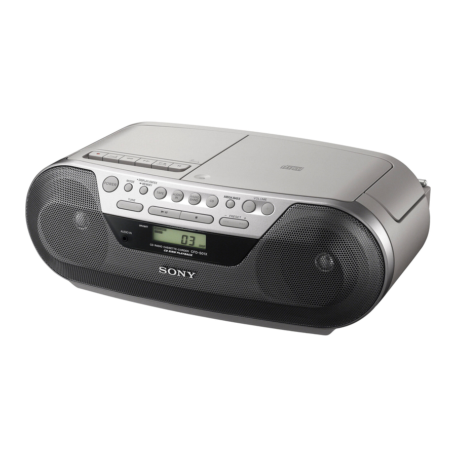
CD RADIO CASSETTE-CORDER
Australian Model
Singapore Model
Taiwan Model
Korea Model
Thai Model
NEW
DA11MMVGP
NEW
MF-S05V
– Continued on next page –
Advertisement
Table of Contents

Summary of Contents for Sony CFD-S05
- Page 1 7 mm aperture.) Number of channels 4-track 2 channel stereo Fast winding time Approx. 150 s (sec.) with Sony cassette C-60 Frequency response 20 Hz - 20,000 Hz +1/–2 dB Frequency response Wow and fl utter...
- Page 2 COMPONENTS IDENTIFIED BY MARK 0 OR DOTTED LINE WITH MARK 0 ON THE SCHEMATIC DIAGRAMS AND IN THE PARTS LIST ARE CRITICAL TO SAFE OPERATION. REPLACE THESE COMPONENTS WITH SONY PARTS WHOSE PART NUMBERS APPEAR AS SHOWN IN THIS MANUAL OR IN SUPPLEMENTS PUBLISHED BY SONY.
- Page 3 CFD-S05 UNLEADED SOLDER TABLE OF CONTENTS Boards requiring use of unleaded solder are printed with the lead- free mark (LF) indicating the solder contains no lead. SERVICING NOTES ..........(Caution: Some printed circuit boards may not come printed with the lead free mark due to their particular size) DISASSEMBLY 2-1.
- Page 4 CFD-S05 SECTION 1 SERVICING NOTES PRECAUTION WHEN INSTALLING A NEW OP UNIT/ CHUCK PLATE JIG ON REPAIRING PRECAUTION BEFORE UNSOLDERING THE STATIC ELECTRICITY PREVENTION SOLDER BRIDGE On repairing CD section, playing a disc without the lid (CD), use Chuck Plate Jig.
- Page 5 CFD-S05 SECTION 2 DISASSEMBLY • This set can be disassembled in the order shown below. 2-1. CABINET (UPPER) SECTION (Page 6) 2-2. CABINET (FRONT) SECTION 2-5. CD BLOCK ASSY (Page 6) (Page 8) 2-10. KEY BOARD 2-6. MOTOR BOARD (Page 10) (Page 8) 2-3.
- Page 6 CFD-S05 Note: Follow the disassembly procedure in the numerical order given. 2-1. CABINET (UPPER) SECTION 5 screw (+BV tapping (B2.6)) 4 two screws (+BV tapping (B2.6)) 3 six screws qs cabinet (upper) section (+BV tapping (B2.6)) 1 battery case lid...
-
Page 7: Main Board
CFD-S05 2-3. MAIN BOARD 2 CN1 (2P) 1 CN901 (3P) 4 three screws (+P tapping (B2.6)) 3 three screws (+P tapping (B2.6)) 5 MAIN board cabinet (rear) section 2-4. POWER BOARD 1 CN901 (3P) 3 screw (+BV tapping (B2.6)) 6 CN903 (2P)


