
Related Manuals for Nokia RM-42


Summary of Contents for Nokia RM-42
- Page 1 Nokia Customer Care Service Manual RM-42 (Nokia N90) Mobile Terminal Part No: (9241872 (Issue 1)) Company Confidential Copyright ©2005 Nokia. All Rights Reserved.
- Page 2 RM-42 Nokia Customer Care Amendment Record Sheet Amendment Record Sheet Amendment No Date Inserted By Comments Issue 1 06/2005 J-PH Page ii Company Confidential 9241872 (Issue 1) Copyright ©2005 Nokia. All Rights Reserved.
- Page 3 Nokia operates a policy of continuous development. Nokia reserves the right to make changes and improvements to any of the products described in this document without prior notice. Under no circumstances shall Nokia be responsible for any loss of data or income or any special, incidental, consequential or indirect damages howsoever caused.
- Page 4 WCDMA networks and cause problems to 3G cellular phone communication in a wide area. • During testing never activate the GSM or WCDMA transmitter without a proper antenna load, otherwise GSM or WCDMA PA may be damaged. Page iv Company Confidential 9241872 (Issue 1) Copyright ©2005 Nokia. All Rights Reserved.
- Page 5 Nokia Customer Care ESD protection Nokia requires that service points have sufficient ESD protection (against static electricity) when servicing the phone. Any product of which the covers are removed must be handled with ESD protection. The SIM card can be replaced without ESD protection if the product is otherwise ready for use.
- Page 6 All of the above suggestions apply equally to the product, battery, charger or any accessory. Page vi Company Confidential 9241872 (Issue 1) Copyright ©2005 Nokia. All Rights Reserved.
- Page 7 While every endeavour has been made to ensure the accuracy of this document, some errors may exist. If any errors are found by the reader, NOKIA MOBILE PHONES Business Group should be notified in writing/e-mail. Please state: • Title of the Document + Issue Number/Date of publication •...
-
Page 8: Battery Information
Do not dispose of batteries in a fire! Dispose of batteries according to local regulations (e.g. recycling). Do not dispose as household waste. Page viii Company Confidential 9241872 (Issue 1) Copyright ©2005 Nokia. All Rights Reserved. - Page 9 5 Disassembly / Reassembly Instructions 6 BB Troubleshooting and Manual Tuning Guide 7 RF Troubleshooting and Manual Tuning Guide 8 Camera Module Troubleshooting 9 System Module 10 Schematics 9241872 (Issue 1) Company Confidential Page ix Copyright ©2005 Nokia. All Rights Reserved.
- Page 10 RM-42 Nokia Customer Care Nokia N90 Service Manual Structure (This page left intentionally blank.) Page x Company Confidential 9241872 (Issue 1) Copyright ©2005 Nokia. All Rights Reserved.
- Page 11 Nokia Customer Care 1 — General Information 9241872 (Issue 1) Company Confidential Page 1–1 Copyright ©2005 Nokia. All Rights Reserved.
- Page 12 RM-42 Nokia Customer Care General Information (This page left intentionally blank.) Page 1–2 Company Confidential 9241872 (Issue 1) Copyright ©2005 Nokia. All Rights Reserved.
-
Page 13: Table Of Contents
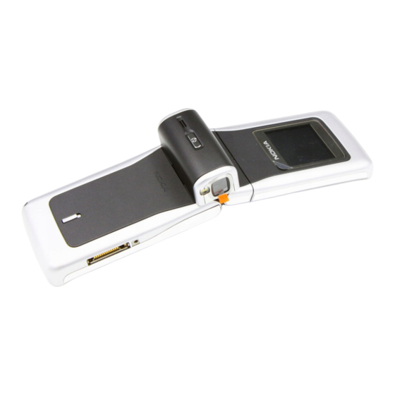
Table 3 Car accessories..................................1–8 Table 4 Pop-PortTM accessories..............................1–8 Table 5 Imaging accessories................................1–9 Table 6 Bluetooth accessories..............................1–9 Table 7 Other accessories................................1–9 List of Figures Figure 1 View of RM-42..................................1–5 9241872 (Issue 1) Company Confidential Page 1–3 Copyright ©2005 Nokia. All Rights Reserved. - Page 14 RM-42 Nokia Customer Care General Information (This page left intentionally blank.) Page 1–4 Company Confidential 9241872 (Issue 1) Copyright ©2005 Nokia. All Rights Reserved.
-
Page 15: Product Selection
384 kbps for downlink and 128 kbps for uplink with simultaneous CS speech (12.2 kbps). For GSM networks the Nokia RM-42 is a class B terminal with EGPRS multislot class 10 (4 Rx + 1 Tx, 3+2) and GPRS multislot class 10 (4+1, 3+2) According to GSM standard 05.05 it responds to class 4 (max. - Page 16 • · Dual mode WCDMA/GSM and triband GSM 900/1800/1900 (WCDMA 2100) • · Codecs: Decoding: MP3, AAC, Real Audio, WAV, Nokia Ring Tones, AMR, AMR-WB, AMR-NB, AU, MIDI, H.263, JPEG, JPEG2000, EXIF 2.2, GIF 87/89, PNG, BMP (W-BMP), MBM, MPEG-4 Encoding: AMR, AMR-NB, AAC, H.263, JPEG, EXIF 2.2, MPEG-4...
-
Page 17: Mobile Enhancements
• · High resolution display 352x416 pixels, up to 262,144 colours • · Landscape oriented user interface for camcorder mode • · Cover display in Nokia Series 60 phone 128x128 pixels up to 65536 colours • · Fold and twist form factor combined with rotating camera unit (four axis concept) •... -
Page 18: Table 2 Chargers
Mobile charger (LCH-12 update) DC-4 Table 4 Pop-Port accessories Pop Port ™ accessories Type Product code Boom mono headset HDB-4 Fashion stereo headset HDS-3 Mono headset HS-5 Stereo headset HS-3 Page 1–8 Company Confidential 9241872 (Issue 1) Copyright ©2005 Nokia. All Rights Reserved. -
Page 19: Table 5 Imaging Accessories
Table 7 Other accessories Other accessories Type Product code 64MB MultiMediaCard MU-1 128MB MultiMediaCard MU-2 256MB MultiMediaCard MU-9 512MB MultiMediaCard MU-12 Connectivity cable DKU-2 Connectivity cable CA-53 9241872 (Issue 1) Company Confidential Page 1–9 Copyright ©2005 Nokia. All Rights Reserved. -
Page 20: Technical Specifications
Number of Tx power levels GSM900: 15 GSM1800: 16 GSM1900: 16 Battery endurance Battery Capacity (mAh) Talk time Stand-by BL-5B up to 3 hrs up to 12 days Page 1–10 Company Confidential 9241872 (Issue 1) Copyright ©2005 Nokia. All Rights Reserved. -
Page 21: Environmental Conditions
Specifications fulfilled C...+55 No operation or storage No storage or operation: an <-40 C...>+85 attempt may damage the phone. Charging allowed C...+50 Long term storage conditions C...+85 9241872 (Issue 1) Company Confidential Page 1–11 Copyright ©2005 Nokia. All Rights Reserved. - Page 22 RM-42 Nokia Customer Care General Information (This page left intentionally blank.) Page 1–12 Company Confidential 9241872 (Issue 1) Copyright ©2005 Nokia. All Rights Reserved.
-
Page 23: Company Confidential Page
Nokia Customer Care 2 — Parts Lists and Component Layouts 9241872 (Issue 1) Company Confidential Page 2–1 Copyright ©2005 Nokia. All Rights Reserved. - Page 24 RM-42 Nokia Customer Care Parts Lists and Component Layouts (This page left intentionally blank.) Page 2–2 Company Confidential 9241872 (Issue 1) Copyright ©2005 Nokia. All Rights Reserved.
-
Page 25: Table Of Contents
Parts lists......................................2–6 Mechanical spare parts overview............................2–6 Mechanical spare parts list..............................2–6 Component parts lists................................2–9 Component layouts..................................2–71 RM-42 component layout - top............................2–71 RM-42 component layout - bottom...........................2–71 List of Tables Table 8 Component parts list..............................2–9 List of Figures Figure 2 RM-42 exploded view..............................2–5... - Page 26 RM-42 Nokia Customer Care Parts Lists and Component Layouts (This page left intentionally blank.) Page 2–4 Company Confidential 9241872 (Issue 1) Copyright ©2005 Nokia. All Rights Reserved.
-
Page 27: Exploded View
RM-42 Parts Lists and Component Layouts Nokia Customer Care Exploded view RM-42 exploded view Figure 2 RM-42 exploded view 9241872 (Issue 1) Company Confidential Page 2–5 Copyright ©2005 Nokia. All Rights Reserved. -
Page 28: Parts Lists
RM-42 Nokia Customer Care Parts Lists and Component Layouts Parts lists Mechanical spare parts overview Mechanical spare parts list Bold=ASSY Page 2–6 Company Confidential 9241872 (Issue 1) Copyright ©2005 Nokia. All Rights Reserved. - Page 29 I015 ??????? DISPLAY SHIELD I016 XXXXXXX A-COVER ASSY XXXXXXX C-COVER ASSY I017 ??????? C-COVER C-COVER TRIM (INCL. I018 XXXXXXX ADHESIVE) I101 ??????? COSMETIC LAYER I102 XXXXXXX E-COVER 9241872 (Issue 1) Company Confidential Page 2–7 Copyright ©2005 Nokia. All Rights Reserved.
- Page 30 I209 DOMESHEET I210 JOYSTICK I211 CAPTURE KEY I212 FLEX FOIL I213 LEDS I214 BB SHIELD ASSY I215 ??????? MICROPHONE CASE I216 ??????? MICROPHONE I217 ??????? PA LID Page 2–8 Company Confidential 9241872 (Issue 1) Copyright ©2005 Nokia. All Rights Reserved.
-
Page 31: Component Parts Lists
Table 8 Component parts list Note: For Nokia product codes, please refer to the latest Service Bulletins on the Partner Website (PWS). To ensure you are always using the latest codes, please check the PWS on a daily basis. Item Side Grid ref. - Page 32 X7R 10% C1481 0402C 50V 0402 Chipcap X7R 10% C1482 0402C 16V 0402 Chipcap X7R 10% C1483 0402C 16V 0402 Chipcap X7R 10% C1484 0402C 16V 0402 Page 2–10 Company Confidential 9241872 (Issue 1) Copyright ©2005 Nokia. All Rights Reserved.
- Page 33 C2005 0402C 16V 0402 Chipcap X7R 10% C2006 0402C 16V 0402 Chipcap X7R 10% C2007 Bottom 0402C 16V 0402 Chipcap X7R 10% C2008 Bottom 0402C 16V 0402 9241872 (Issue 1) Company Confidential Page 2–11 Copyright ©2005 Nokia. All Rights Reserved.
- Page 34 X7R 10% C2204 0402C 50V 0402 Chipcap X7R 10% C2205 0402C 50V 0402 Chipcap X7R 10% C2206 0402C 50V 0402 Chipcap X7R 10% C2207 0402C 50V 0402 Page 2–12 Company Confidential 9241872 (Issue 1) Copyright ©2005 Nokia. All Rights Reserved.
- Page 35 6V3 0603 6.3V CHIPCAP X5R 1U K C2221 0603C 6V3 0603 6.3V CHIPCAP X5R 1U K C2222 0603C 6V3 0603 6.3V Chipcap X7R 10% C2223 0402C 16V 0402 9241872 (Issue 1) Company Confidential Page 2–13 Copyright ©2005 Nokia. All Rights Reserved.
- Page 36 16V 0402 CHIPCAP X5R 22U M C2301 0805C 6V3 0805 CHIPCAP X5R 22U M C2302 0805C 6V3 0805 CHIPCAP X5R 1U K C2303 0603C 6V3 0603 6.3V Page 2–14 Company Confidential 9241872 (Issue 1) Copyright ©2005 Nokia. All Rights Reserved.
- Page 37 CHIPCAP X5R 100N M 16V C2801 0402C 0402 100n CHIPCAP X5R 100N M 16V C2802 0402C 0402 100n CHIPCAP X5R 100N M 16V C2803 0402C 0402 100n 9241872 (Issue 1) Company Confidential Page 2–15 Copyright ©2005 Nokia. All Rights Reserved.
- Page 38 CHIPCAP X5R 100N M 16V C2812 0402C 0402 100n CHIPCAP X5R 100N M 16V C2813 0402C 0402 100n CHIPCAP X5R 100N M 16V C2814 0402C 0402 100n Page 2–16 Company Confidential 9241872 (Issue 1) Copyright ©2005 Nokia. All Rights Reserved.
- Page 39 16V 0402 CHIPCAP X5R 100N M 16V C3008 0402C 0402 100n CHIPCAP X5R 22U M C4200 0805C 6V3 0805 CHIPCAP X5R 22U M C4201 0805C 6V3 0805 9241872 (Issue 1) Company Confidential Page 2–17 Copyright ©2005 Nokia. All Rights Reserved.
- Page 40 CHIPCAP X5R 100N M 16V C4804 0402C 0402 100n CHIPCAP X5R 100N M 16V C4805 0402C 0402 100n CHIPCAP X5R 100N M 16V C4806 0402C 0402 100n Page 2–18 Company Confidential 9241872 (Issue 1) Copyright ©2005 Nokia. All Rights Reserved.
- Page 41 CHIPCAP X5R 100N M 16V C5001 0402C 0402 100n CHIPCAP X5R 100N M 16V C5002 0402C 0402 100n CHIPCAP X5R 100N M 16V C5003 0402C 0402 100n 9241872 (Issue 1) Company Confidential Page 2–19 Copyright ©2005 Nokia. All Rights Reserved.
- Page 42 CHIPCAP X5R 0U47 K C6041 0402C 6.3V 0402 0u47 CHIPCAP X5R 1U K C6042 0402C 6V3 0402 6.3V CHIPCAP X5R 0U47 K C6043 0402C 6.3V 0402 0u47 Page 2–20 Company Confidential 9241872 (Issue 1) Copyright ©2005 Nokia. All Rights Reserved.
- Page 43 CHIPCAP X5R 100N M 16V C7518 Bottom 0402C 0402 100n Chipcap C7520 Bottom 0402C 5% NP0 Chipcap C7522 Bottom 0402C 5% NP0 150p Chipcap +-0.25pF C7523 0402C 9241872 (Issue 1) Company Confidential Page 2–21 Copyright ©2005 Nokia. All Rights Reserved.
- Page 44 0402C 16V 0402 Chipcap C7537 0402C 5% NP0 100p Chipcap C7538 0402C 5% NP0 100p Chipcap C7539 0402C 5% NP0 100p Chipcap C7540 Bottom 0402C 5% NP0 Page 2–22 Company Confidential 9241872 (Issue 1) Copyright ©2005 Nokia. All Rights Reserved.
- Page 45 Chipcap +-0.25pF C7554 Bottom 0402C CHIPCAP NP0 0P5 C C7555 Bottom 0402C 50V 0402 Chipcap C7556 0402C 5% NP0 Chipcap X7R 10% C7558 Bottom 0402C 50V 0402 9241872 (Issue 1) Company Confidential Page 2–23 Copyright ©2005 Nokia. All Rights Reserved.
- Page 46 0603C 16V 0603 Chipcap C7575 Bottom 0402C 5% NP0 Chipcap X7R 10% C7576 0402C 50V 0402 Chipcap C7577 Bottom 0402C 5% NP0 Chipcap C7578 0402C 5% NP0 Page 2–24 Company Confidential 9241872 (Issue 1) Copyright ©2005 Nokia. All Rights Reserved.
- Page 47 CHIPCAP NP0 470P J C7591 0402C 6V3 0402 470p Chipcap C7592 0402C 5% X7R CHIPCAP X5R 4U7 K C7593 0603C 6V3 0603 6.3V Chipcap +-0.25pF C7595 0402C 9241872 (Issue 1) Company Confidential Page 2–25 Copyright ©2005 Nokia. All Rights Reserved.
- Page 48 +512MNA FBGA133 32Mx16/ D5000 FBGA133 PBFREE 64Mx8 0603_FUSE _AVX2MAT SM FUSE F F2000 Bottom 2.0A 32V VCO 3610- VCO_FDK_ 4340MHZ 3610- G7500 Bottom WB002 2.7V 15MA 4340MHz Page 2–26 Company Confidential 9241872 (Issue 1) Copyright ©2005 Nokia. All Rights Reserved.
- Page 49 100M 2A 220R/ L2202 0603_BLM 0R05 0603 100MHz FERRITE BEAD 0.6R 600R/ FERRITE_0 100MHZ 600R/ L2203 0402 100MHz FERRITE BEAD 0.6R 600R/ FERRITE_0 100MHZ 600R/ L2204 0402 100MHz 9241872 (Issue 1) Company Confidential Page 2–27 Copyright ©2005 Nokia. All Rights Reserved.
- Page 50 L4201 0603_BLM 0R05 0603 100MHz FERRITE BEAD 0.6R 600R/ FERRITE_0 100MHZ 600R/ L4400 Bottom 0402 100MHz FERRITE BEAD 0.6R 600R/ FERRITE_0 100MHZ 600R/ L4401 Bottom 0402 100MHz Page 2–28 Company Confidential 9241872 (Issue 1) Copyright ©2005 Nokia. All Rights Reserved.
- Page 51 10N J Q30/ L7511 Bottom 0402L 800M 0402 10nH CHIP COIL 4N7 +-0N3 Q28/800M L7512 Bottom 0402L 0402 4n7H CHIP COIL 1N8+-0N3 Q31/800M L7513 Bottom 0402L 0402 1n8H 9241872 (Issue 1) Company Confidential Page 2–29 Copyright ©2005 Nokia. All Rights Reserved.
- Page 52 TFBGA_108 TFBGA108 TAHVO V4.1 LEADFREE TFBGA_84_ TFBGA84 N2300 6.15X6.15 WHITE LED DRIVER 4LEDS 500MW USMD8_1.6 8BUMP N2301 9X1.69 USMD8 DC_DC CONV USMD_10_ LM2708H- 2.458X1.8 1.40V/ N4200 1.09V Page 2–30 Company Confidential 9241872 (Issue 1) Copyright ©2005 Nokia. All Rights Reserved.
- Page 53 R1473 0402R 5% 63mW Resistor R1474 0402R 5% 63mW 150R Resistor R1475 0402R 5% 63mW Resistor R1476 0402R 5% 63mW 100R Resistor R1477 0402R 5% 63mW 100R 9241872 (Issue 1) Company Confidential Page 2–31 Copyright ©2005 Nokia. All Rights Reserved.
- Page 54 Bottom uBGA5 BGA5 ASIP SILIC uBGA11_1. USB OTG / R2007 6X2.15 ESD BGA11 NETWORK 0W06 220K/120K R2008 0404_RP J 0404 220k/120k Resistor R2009 0402R 5% 63mW 100R Page 2–32 Company Confidential 9241872 (Issue 1) Copyright ©2005 Nokia. All Rights Reserved.
- Page 55 5% 63mW Resistor R2303 0402R 5% 63mW Resistor R2304 0402R 5% 63mW Resistor R2305 0402R 5% 63mW Resistor R2307 0402R 5% 63mW Resistor R2308 0402R 5% 63mW 9241872 (Issue 1) Company Confidential Page 2–33 Copyright ©2005 Nokia. All Rights Reserved.
- Page 56 VWM14V VC50V R5204 Bottom 0402_VAR 0402 14V/50V Resistor R7501 Bottom 0402R 5% 63mW Resistor R7503 Bottom 0402R 5% 63mW CHIPRES 0W06 10K R7504 Bottom 0402R F 0402 Page 2–34 Company Confidential 9241872 (Issue 1) Copyright ©2005 Nokia. All Rights Reserved.
- Page 57 R7525 0402R 5% 63mW Resistor R7526 0402R 5% 63mW Resistor R7527 0402R 5% 63mW 220R Resistor R7528 Bottom 0402R 5% 63mW 470k Resistor R7529 0402R 5% 63mW 9241872 (Issue 1) Company Confidential Page 2–35 Copyright ©2005 Nokia. All Rights Reserved.
- Page 58 0805 TVS DI 1PMT16AT 3 16V 175W V2000 Bottom CASE_457 PWRMITE DTC143ZM N RB=4K7 RBE=47K V2300 VMT3_R VMT3 2SC5658Q RS N 50V 0A1 0W15 V2301 VMT3 VMT3 Page 2–36 Company Confidential 9241872 (Issue 1) Copyright ©2005 Nokia. All Rights Reserved.
- Page 59 006_139_2 P2.54 MOLEX_50 SM CONN 0024_500 2X25F P0.4 X4400 PWB/PWB SM CONN MOLEX_51 BTB 2X15F X4401 338_0304 P0.4 CONN MMC CONN_CT7_ 6P RS 00220_20 PUSH- X5200 PUSH 9241872 (Issue 1) Company Confidential Page 2–37 Copyright ©2005 Nokia. All Rights Reserved.
- Page 60 2441.75M Z6030 M77S_V2 Z 2.0X1.5 FERRITE BEAD 0R01 28R/ FERRITE_FB 100MHZ 28R/ Z7500 MJ1608 0603 100MHz FILTER FILTER_SA 2140 W_2.1X1.7 +-30MHZ/ Z7501 Bottom _H0.8 4DB 2X1.6 2140MHz Page 2–38 Company Confidential 9241872 (Issue 1) Copyright ©2005 Nokia. All Rights Reserved.
- Page 61 BT CAN SHIELD_DM DMC07003 A6000 C07003 RM-1 RF ENGINE SHIELD_DM DMC07006 A7000 C07006 RM-1 WDCMA PA SHIELD_DM DMC07007 A7001 C07007 RM-1 GSM PA SHIELD_DM DMC07005 A7002 C07005 RM-1 9241872 (Issue 1) Company Confidential Page 2–39 Copyright ©2005 Nokia. All Rights Reserved.
- Page 62 X7R 10% C2005 0402C 16V 0402 Chipcap X7R 10% C2006 0402C 16V 0402 Chipcap X7R 10% C2007 0402C 16V 0402 Chipcap X7R 10% C2008 0402C 16V 0402 Page 2–40 Company Confidential 9241872 (Issue 1) Copyright ©2005 Nokia. All Rights Reserved.
- Page 63 X7R 10% C2107 0402C 50V 0402 Chipcap X7R 10% C2108 0402C 50V 0402 Chipcap X7R 10% C2109 0402C 50V 0402 Chipcap X7R 10% C2110 0402C 50V 0402 9241872 (Issue 1) Company Confidential Page 2–41 Copyright ©2005 Nokia. All Rights Reserved.
- Page 64 CHIPCAP X5R 1U K C2212 0603C 6V3 0603 6.3V CHIPCAP X5R 1U K C2213 0603C 6V3 0603 6.3V CHIPCAP X5R 1U K C2214 0603C 6V3 0603 6.3V Page 2–42 Company Confidential 9241872 (Issue 1) Copyright ©2005 Nokia. All Rights Reserved.
- Page 65 CHIPCAP X5R 1U K C2227 0603C 6V3 0603 6.3V CHIPCAP X5R 1U K C2228 0603C 6V3 0603 6.3V CHIPCAP X5R 1U K C2230 0603C 6V3 0603 6.3V 9241872 (Issue 1) Company Confidential Page 2–43 Copyright ©2005 Nokia. All Rights Reserved.
- Page 66 0805C 6V3 0805 CHIPCAP X5R 22U M C2302 0805C 6V3 0805 CHIPCAP X5R 1U K C2303 0603C 6V3 0603 6.3V Chipcap X7R 10% C2304 0402C 16V 0402 Page 2–44 Company Confidential 9241872 (Issue 1) Copyright ©2005 Nokia. All Rights Reserved.
- Page 67 CHIPCAP X5R 100N M 16V C2801 0402C 0402 100n CHIPCAP X5R 100N M 16V C2802 0402C 0402 100n CHIPCAP X5R 100N M 16V C2803 0402C 0402 100n 9241872 (Issue 1) Company Confidential Page 2–45 Copyright ©2005 Nokia. All Rights Reserved.
- Page 68 CHIPCAP X5R 100N M 16V C2812 0402C 0402 100n CHIPCAP X5R 100N M 16V C2813 0402C 0402 100n CHIPCAP X5R 100N M 16V C2814 0402C 0402 100n Page 2–46 Company Confidential 9241872 (Issue 1) Copyright ©2005 Nokia. All Rights Reserved.
- Page 69 C3008 0402C 0402 100n CHIPCAP X5R 22U M C4200 0805C 6V3 0805 CHIPCAP X5R 22U M C4201 0805C 6V3 0805 Chipcap X7R 10% C4202 0402C 16V 0402 9241872 (Issue 1) Company Confidential Page 2–47 Copyright ©2005 Nokia. All Rights Reserved.
- Page 70 CHIPCAP X5R 100N M 16V C4806 0402C 0402 100n CHIPCAP X5R 100N M 16V C4807 0402C 0402 100n CHIPCAP X5R 100N M 16V C4808 0402C 0402 100n Page 2–48 Company Confidential 9241872 (Issue 1) Copyright ©2005 Nokia. All Rights Reserved.
- Page 71 CHIPCAP X5R 100N M 16V C5003 0402C 0402 100n CHIPCAP X5R 100N M 16V C5004 0402C 0402 100n CHIPCAP X5R 100N M 16V C5005 0402C 0402 100n 9241872 (Issue 1) Company Confidential Page 2–49 Copyright ©2005 Nokia. All Rights Reserved.
- Page 72 0402C CHIPCAP X5R 2U2 K C6047 0603C 6V3 0603 Chipcap +-0.25pF C6048 0402C Chipcap C7501 0402C 5% NP0 CHIPCAP X5R 1U K C7503 0603C 6V3 0603 6.3V Page 2–50 Company Confidential 9241872 (Issue 1) Copyright ©2005 Nokia. All Rights Reserved.
- Page 73 C7518 0402C 0402 100n Chipcap C7520 0402C 5% NP0 Chipcap C7522 0402C 5% NP0 150p Chipcap +-0.25pF C7523 0402C CHIPCAP NP0 2N2 G C7524 0603C 16V 0603 9241872 (Issue 1) Company Confidential Page 2–51 Copyright ©2005 Nokia. All Rights Reserved.
- Page 74 6.3V CHIPCAP X5R 1U K C7543 0603C 6V3 0603 6.3V Chipcap +-0.25pF C7545 0402C Chipcap +-0.25pF C7547 0402C CHIPCAP X5R 1U K C7548 0603C 6V3 0603 6.3V Page 2–52 Company Confidential 9241872 (Issue 1) Copyright ©2005 Nokia. All Rights Reserved.
- Page 75 25V 0402 Chipcap +-0.25pF C7561 0402C Chipcap +-0.25pF C7563 0402C Chipcap X7R 10% C7564 0402C 50V 0402 Chipcap C7567 0402C 5% NP0 Chipcap C7568 0402C 5% NP0 150p 9241872 (Issue 1) Company Confidential Page 2–53 Copyright ©2005 Nokia. All Rights Reserved.
- Page 76 0402C 50V 0402 Chipcap C7586 0402C 5% NP0 Chipcap C7587 0402C 5% NP0 CHIPCAP X5R 4U7 K C7589 0603C 6V3 0603 6.3V Chipcap C7590 0402C 5% NP0 Page 2–54 Company Confidential 9241872 (Issue 1) Copyright ©2005 Nokia. All Rights Reserved.
- Page 77 BIT_BGA60 1.8V/1.8V _PBFREE_M WBGA60 D3001 PBFREE 4Mx16 HELEN3 PS1.1E F761991A C027 D4800 uBGA_289 UBGA289 COMBO 256M DDR + 256M 256M_DDR NAND FBGA121_ FBGA121 256M_NAN D5000 H1.1 PBFREE 9241872 (Issue 1) Company Confidential Page 2–55 Copyright ©2005 Nokia. All Rights Reserved.
- Page 78 0405_2_M 2X1000R 2x1000R/ L2003 ATSU 0405 100MHz CHIP BEAD ARRAY 0405_2_M 2X1000R 2x1000R/ L2100 ATSU 0405 100MHz FERR.BEAD 220R/ 100M 2A 220R/ L2101 0603_BLM 0R05 0603 100MHz Page 2–56 Company Confidential 9241872 (Issue 1) Copyright ©2005 Nokia. All Rights Reserved.
- Page 79 600R/ FERRITE_0 100MHZ 600R/ L2204 0402 100MHz FERR.BEAD 220R/ 100M 2A 220R/ L2205 0603_BLM 0R05 0603 100MHz FERRITE BEAD 0.6R 600R/ FERRITE_0 100MHZ 600R/ L2206 0402 100MHz 9241872 (Issue 1) Company Confidential Page 2–57 Copyright ©2005 Nokia. All Rights Reserved.
- Page 80 BEAD 0.6R 600R/ FERRITE_0 100MHZ 600R/ L4401 0402 100MHz FERRITE BEAD 0.6R 600R/ FERRITE_0 100MHZ 600R/ L5200 0402 100MHz CHIP COIL 2N7+-0N3 Q29/800M L6031 0402L 0402 2n7H Page 2–58 Company Confidential 9241872 (Issue 1) Copyright ©2005 Nokia. All Rights Reserved.
- Page 81 10N J Q30/ L7511 0402L 800M 0402 10nH CHIP COIL 4N7 +-0N3 Q28/800M L7512 0402L 0402 4n7H CHIP COIL 8N2 J Q28/ 800MHZ L7514 0402L 0402 8n2H 9241872 (Issue 1) Company Confidential Page 2–59 Copyright ©2005 Nokia. All Rights Reserved.
- Page 82 USMD8 DC_DC CONV USMD_10_ LM2708H- 2.458X1.8 1.40V/ N4200 1.09V BC3-ROM WITH BC2 TFBGA84_ MOULD N6030 H1.0 MATERIAL VREG 2.85/ 150MA LP3987- USMD5_1.4 2.85 N6031 68X1.036 USMD5 2.85V Page 2–60 Company Confidential 9241872 (Issue 1) Copyright ©2005 Nokia. All Rights Reserved.
- Page 83 W/ESD RES uBGA11_2. +CAP+ZDI R2001 15X1.65 BGA11 Resistor R2002 0402R 5% 63mW Resistor R2003 0402R 5% 63mW Resistor R2004 0402R 5% 63mW Resistor R2005 0402R 5% 63mW 9241872 (Issue 1) Company Confidential Page 2–61 Copyright ©2005 Nokia. All Rights Reserved.
- Page 84 R2071 +-3% 0402 ASIP SINGLE ENDED MICROPHO FLIP_CHIP_ NE INTERF R2100 8_1.7X1.7 BGA8 Resistor R2101 0402R 5% 63mW 220R CHIP VARISTOR VWM14V VC50V R2104 0402_VAR 0402 14V/50V Page 2–62 Company Confidential 9241872 (Issue 1) Copyright ©2005 Nokia. All Rights Reserved.
- Page 85 Resistor R2303 0402R 5% 63mW Resistor R2304 0402R 5% 63mW Resistor R2305 0402R 5% 63mW ASIP EMIF03- SIM01F2 **PB- R2700 uBGA8 FREE** Resistor R3000 0402R 5% 63mW 9241872 (Issue 1) Company Confidential Page 2–63 Copyright ©2005 Nokia. All Rights Reserved.
- Page 86 R4408 0603_VAR 0603 19V/27V CHIP VARISTOR VWM19V VC27V R4409 0603_VAR 0603 19V/27V Resistor R4800 0402R 5% 63mW Resistor R4809 0402R 5% 63mW Resistor R5100 0402R 5% 63mW Page 2–64 Company Confidential 9241872 (Issue 1) Copyright ©2005 Nokia. All Rights Reserved.
- Page 87 Resistor R7514 0402R 5% 63mW Resistor R7516 0402R 5% 63mW Resistor R7518 0402R 5% 63mW 470k Resistor R7519 0402R 5% 63mW Resistor R7520 0402R 5% 63mW 270R 9241872 (Issue 1) Company Confidential Page 2–65 Copyright ©2005 Nokia. All Rights Reserved.
- Page 88 RE_II 1.75 SM TACT SW TRAV SWITCH_SK 4.1X3.55X S4401 RE_II 1.75 SM SW DETECTOR SWITCH_SP SPST-NO S5200 VN220100 5V 1MA TRANSF BALUN 2134 TRANS_LD +-90MHZ T7500 0805 Page 2–66 Company Confidential 9241872 (Issue 1) Copyright ©2005 Nokia. All Rights Reserved.
- Page 89 SCHDIX2 RF DETECTOR CT 1PF 0V39 V7500 SOT_563 SOT666 CAMERA MOD.SOCKE SOCKET_D T 2X7POL X1470 MD10413 SPR P1.4 SYSCON_M SM SYSTEM Q202_NK_ CONNECTO X2001 14R3 R 14POL 9241872 (Issue 1) Company Confidential Page 2–67 Copyright ©2005 Nokia. All Rights Reserved.
- Page 90 FORK FORK_SPRI SPRING NG_040_00 040- 0443_RM_ 000443 X4404 RM-1 FORK FORK_SPRI SPRING NG_040_00 040- 0443_RM_ 000443 X4405 RM-1 MOLEX_MM CONN SMC C_P03_3D0 RS-MMC X5200 545_001 6POL P2.5 Page 2–68 Company Confidential 9241872 (Issue 1) Copyright ©2005 Nokia. All Rights Reserved.
- Page 91 EZFVQ42N +-41.75MH 2441.75M Z6030 M61S Z 2.5X2 FERRITE BEAD 0R01 28R/ FERRITE_FB 100MHZ 28R/ Z7500 MJ1608 0603 100MHz FILTER 2140 FILTER_SA +-30MHZ W_2.1X1.7 2.0X1.6X1. Z7501 _H0.8 2140MHz 9241872 (Issue 1) Company Confidential Page 2–69 Copyright ©2005 Nokia. All Rights Reserved.
- Page 92 1990MHZ FILTER FILTER_SA 897.5 W_2.1X1.7 +-17.5MHZ Z7504 _H0.8 2.0X1.6 897.5MHz ISOLATOR 1950 +-30MHZ 13DB ISOLATOR_ 3.3X3.4X1. Z7505 CEZ0047 FILTER 1950 FILTER_SA +-30MHZ W_2.1X1.7 2.0X1.6X1. Z7506 _H0.8 1950MHz Page 2–70 Company Confidential 9241872 (Issue 1) Copyright ©2005 Nokia. All Rights Reserved.
-
Page 93: Component Layouts
RM-42 Parts Lists and Component Layouts Nokia Customer Care Component layouts RM-42 component layout - top RM-42 component layout - bottom 9241872 (Issue 1) Company Confidential Page 2–71 Copyright ©2005 Nokia. All Rights Reserved. - Page 94 RM-42 Nokia Customer Care Parts Lists and Component Layouts (This page left intentionally blank.) Page 2–72 Company Confidential 9241872 (Issue 1) Copyright ©2005 Nokia. All Rights Reserved.
- Page 95 Nokia Customer Care 3 — Service Software Instructions 9241872 (Issue 1) Company Confidential Page 3–1 Copyright ©2005 Nokia. All Rights Reserved.
- Page 96 RM-42 Nokia Customer Care Service Software Instructions (This page left intentionally blank.) Page 3–2 Company Confidential 9241872 (Issue 1) Copyright ©2005 Nokia. All Rights Reserved.
- Page 97 Figure 29 Prommer SW update finished..........................3–22 Figure 30 Prommer maintenance window..........................3–23 Figure 31 Flash directory window............................3–23 Figure 32 Prommer maintenance............................3–24 Figure 33 Box activation................................3–24 Figure 34 Deactivation warning..............................3–25 9241872 (Issue 1) Company Confidential Page 3–3 Copyright ©2005 Nokia. All Rights Reserved.
- Page 98 RM-42 Nokia Customer Care Service Software Instructions (This page left intentionally blank.) Page 3–4 Company Confidential 9241872 (Issue 1) Copyright ©2005 Nokia. All Rights Reserved.
-
Page 99: Phoenix Installation Steps In Brief
3. Install the phone-specific Data Package for Phoenix. 4. Configure users. 5. Manage connection settings (depends on the tools you are using). If you use FPS-8: • Update FPS-8 SW • Activate FPS-8 9241872 (Issue 1) Company Confidential Page 3–5 Copyright ©2005 Nokia. All Rights Reserved. -
Page 100: Installing Phoenix
Press the F1 key or the feature’s Help button to activate a Help file. Steps 1. To start installation, run the application file (for example,phoenix_service_sw_2004_39_x_xx.exe). 2. In the Welcome dialogue, click Next. Page 3–6 Company Confidential 9241872 (Issue 1) Copyright ©2005 Nokia. All Rights Reserved. - Page 101 3. Read the disclaimer text carefully and click Yes. Figure 4 Disclaimer text 4. Choose destination folder. The default folder C:\ProgramFiles\Nokia\Phoenix is recommended. 5. To continue, click Next. To choose another location, click Browse (not recommended). 6. Wait for the components to be copied.
-
Page 102: Updating Phoenix Installation
Windows Control Panel. • If you try to install an older version (for example, downgrade from a15_2004_24_7_55 to a14_2004_16_4_47), installation will be interrupted. Page 3–8 Company Confidential 9241872 (Issue 1) Copyright ©2005 Nokia. All Rights Reserved. -
Page 103: Uninstalling Phoenix
1. Open the Windows Control Panel and choose Add/Remove Programs. 2. To uninstall Phoenix, choose Phoenix Service Software → Change/Remove → Remove . Figure 7 Remove program The progress of the uninstallation is shown. 9241872 (Issue 1) Company Confidential Page 3–9 Copyright ©2005 Nokia. All Rights Reserved. -
Page 104: Repairing Phoenix Installation
PC when you run the repair setup. Steps 1. Open Windows Control Panel → Add/Remove Programs . 2. Select Phoenix Service Software → Change/Remove . Page 3–10 Company Confidential 9241872 (Issue 1) Copyright ©2005 Nokia. All Rights Reserved. -
Page 105: Phoenix Service Software Data Package Overview
• Files for type label printing • Validation file for the Faultlog repair data reporting system • All product-specific configuration files for Phoenix software components Data files are stored under C:\Program Files\Nokia\Phoenix (default). Installing Phoenix data package Before you begin •... - Page 106 In this view you can see the contents of the data package. Read the text carefully. There is information about the Phoenix version required with this data package. Page 3–12 Company Confidential 9241872 (Issue 1) Copyright ©2005 Nokia. All Rights Reserved.
- Page 107 5. Confirm location and click Next to continue. Figure 12 Data package destination folder The install shield checks where the Phoenix application is installed and the directory is shown. 9241872 (Issue 1) Company Confidential Page 3–13 Copyright ©2005 Nokia. All Rights Reserved.
- Page 108 You now have all phone model specific files installed in your Phoenix Service SW. Next action Phoenix can be used, for example, for flashing phones and printing type labels after: • Configuring users • Managing connections Page 3–14 Company Confidential 9241872 (Issue 1) Copyright ©2005 Nokia. All Rights Reserved.
-
Page 109: Uninstalling Phoenix Data Package
• You can also uninstall the data package manually from Windows Control Panel → Add/Remove Programs → xx-xx * Phone Data Package . (*= type designator of the phone) Next action Run the installation package again to continue installation from the beginning. 9241872 (Issue 1) Company Confidential Page 3–15 Copyright ©2005 Nokia. All Rights Reserved. -
Page 110: Configuring Users In Phoenix
With the Manage Connections feature you can edit and delete existing connections and create new ones. Steps 1. Start Phoenix Service SW and log in. 2. Choose File → Manage Connections . Page 3–16 Company Confidential 9241872 (Issue 1) Copyright ©2005 Nokia. All Rights Reserved. - Page 111 When the phone is connected to a PC for the first time, allow the PC to install the USB device drivers first. Please note that this may take some time to complete. 9241872 (Issue 1) Company Confidential Page 3–17 Copyright ©2005 Nokia. All Rights Reserved.
- Page 112 The connection is now selected and can be used after closing the Manage Connections window. The selected connection is shown on the right hand bottom corner of the screen. Figure 21 Connection information Page 3–18 Company Confidential 9241872 (Issue 1) Copyright ©2005 Nokia. All Rights Reserved.
-
Page 113: Installing Flash Support Files For Fps-8 And Fps-10
If you are not using a separate installation package, you can skip this section and continue with Updating FPS- 8 and FPS-10 flash prommer software (Page 3–22) after installing a new phone data package. 9241872 (Issue 1) Company Confidential Page 3–19 Copyright ©2005 Nokia. All Rights Reserved. - Page 114 Windows Control Panel and then rerun the installation. Figure 25 Flash installation interrupted If an older version exists on your PC and it needs to be updated, click Next to continue installation. Page 3–20 Company Confidential 9241872 (Issue 1) Copyright ©2005 Nokia. All Rights Reserved.
- Page 115 RM-42 Service Software Instructions Nokia Customer Care 3. It is highly recommended to install the files to the default destination folder C:\Program Files\Nokia \Phoenix. To continue, click Next. Figure 26 Flash destination folder When installing the flash update files for the first time, you may choose another location by selecting Browse (not recommended).
-
Page 116: Updating Fps-8 And Fps-10 Flash Prommer Software
4. Wait until you are notified that the update has been successful; the procedure will take a couple of minutes. To close the Prommer Maintenance window, click OK. Figure 29 Prommer SW update finished Page 3–22 Company Confidential 9241872 (Issue 1) Copyright ©2005 Nokia. All Rights Reserved. -
Page 117: Activating Fps-8
More information can be found in the Phoenix Help. Activating FPS-8 Context Before FPS-8 can be successfully used for phone programming, it must first be activated. 9241872 (Issue 1) Company Confidential Page 3–23 Copyright ©2005 Nokia. All Rights Reserved. -
Page 118: Deactivating Fps-8
First fill in the FPS-8 activation request sheet in the FPS-8 sales package and follow the instructions given. When activation file is received (for example, 00000.in), copy it to the C:\ProgramFiles\Nokia\Phoenix \BoxActivation directory on your computer (this directory is created when Phoenix is installed). - Page 119 Service Software Instructions Nokia Customer Care 4. To confirm the deactivation, click Yes. Figure 34 Deactivation warning The box is deactivated. 5. To complete the deactivation, restart FPS-8. 9241872 (Issue 1) Company Confidential Page 3–25 Copyright ©2005 Nokia. All Rights Reserved.
- Page 120 RM-42 Nokia Customer Care Service Software Instructions (This page left intentionally blank.) Page 3–26 Company Confidential 9241872 (Issue 1) Copyright ©2005 Nokia. All Rights Reserved.
- Page 121 Nokia Customer Care 4 — Service Tools and Service Concepts 9241872 (Issue 1) Company Confidential Page 4–1 Copyright ©2005 Nokia. All Rights Reserved.
- Page 122 RM-42 Nokia Customer Care Service Tools and Service Concepts (This page left intentionally blank.) Page 4–2 Company Confidential 9241872 (Issue 1) Copyright ©2005 Nokia. All Rights Reserved.
- Page 123 Figure 37 POS flash concept..............................4–13 Figure 38 Service concept for RF testing and RF/BB tuning....................4–14 Figure 39 CU-4 flash concept with FPS-10..........................4–15 Figure 40 RF testing concept with RF coupler........................4–16 9241872 (Issue 1) Company Confidential Page 4–3 Copyright ©2005 Nokia. All Rights Reserved.
- Page 124 RM-42 Nokia Customer Care Service Tools and Service Concepts (This page left intentionally blank.) Page 4–4 Company Confidential 9241872 (Issue 1) Copyright ©2005 Nokia. All Rights Reserved.
-
Page 125: Service Tools
• Forwards USB traffic to/from terminal • software controlled BSI values • regulated VBATT voltage • 2 x USB2.0 connector (Hub) • FBUS and USB connections supported 9241872 (Issue 1) Company Confidential Page 4–5 Copyright ©2005 Nokia. All Rights Reserved. - Page 126 • Power Supply with 5 country specific cords • USB cable FS-1 Product specific adapter FS-1 is a product specific adapter, compatible with SS-62 and SS-46. It provides galvanic connection to terminal test pads. Page 4–6 Company Confidential 9241872 (Issue 1) Copyright ©2005 Nokia. All Rights Reserved.
- Page 127 This tool is used for LGA type component reworking purposes. PCS-1 Power cable The PCS-1 power cable (DC) is used with a control unit CU-4 to supply a controlled operating voltage. 9241872 (Issue 1) Company Confidential Page 4–7 Copyright ©2005 Nokia. All Rights Reserved.
-
Page 128: Rf Shield Box
SES-3 Stencil SES-3 stencil is used with MJS-76 / 0770417 and it supports the PA component. SES-3 is made for reworking purposes used in central service level. Page 4–8 Company Confidential 9241872 (Issue 1) Copyright ©2005 Nokia. All Rights Reserved. - Page 129 • provides standardised interface towards Control Unit • provides RF connection using galvanic connector or coupler • multiplexing between USB and FBUS media, controlled by VUSB SS-67 Assembly jig for mechanics disassembly/ reassembly 9241872 (Issue 1) Company Confidential Page 4–9 Copyright ©2005 Nokia. All Rights Reserved.
- Page 130 The RF cable is used to connect, for example, a module repair jig to the RF measurement equipment. SMA to N-Connector ca. 610mm. Attenuation for: • GSM850/900: 0.3+-0.1 dB • GSM1800/1900: 0.5+-0.1 dB • WLAN: 0.6+-0.1dB Page 4–10 Company Confidential 9241872 (Issue 1) Copyright ©2005 Nokia. All Rights Reserved.
-
Page 131: Service Concepts
FS-1 Product specific adapter SS-46 Interface adapter CA-35S Power cable XCS-4 Modular cable Standard USB cable FPS-10 Flash prommer box Standard USB cable PKD-1 SW security device 9241872 (Issue 1) Company Confidential Page 4–11 Copyright ©2005 Nokia. All Rights Reserved. -
Page 132: Module Jig Concept
SX-4 Smart card XCS-4 Modular cable PCS-1 DC power cable Standard USB cable Standard USB cable GPIB control cable XRF-1 RF antenna cable PKD-1 SW security device Page 4–12 Company Confidential 9241872 (Issue 1) Copyright ©2005 Nokia. All Rights Reserved. -
Page 133: Pos (Point Of Sale) Flash Concept
Item 12 not shown in the picture. POS (Point of Sale) flash concept Figure 37 POS flash concept Item Type Description DKU-2/CA-53 USB connectivity cable AC-4 Charger 9241872 (Issue 1) Company Confidential Page 4–13 Copyright ©2005 Nokia. All Rights Reserved. -
Page 134: Service Concept For Rf Testing And Rf/Bb Tuning
Standard USB cable + smart card reader SX-4 Smart card XRS-6 RF cable GPIB control cable PKD-1 SW security device RF shield box Note: Item 10 not shown in the picture. Page 4–14 Company Confidential 9241872 (Issue 1) Copyright ©2005 Nokia. All Rights Reserved. -
Page 135: Flash Concept With Fps-10
Control unit PCS-1 Power cable XCS-4 Modular cable FPS-10 Flash prommer box Standard USB cable Standard USB cable PKD-1 SW security device SS-62 Flash adapter base for BB5 9241872 (Issue 1) Company Confidential Page 4–15 Copyright ©2005 Nokia. All Rights Reserved. -
Page 136: Rf Testing Concept With Rf Coupler
Standard USB cable + smart card reader SX-4 Smart card GPIB control cable XRS-6 RF cable PKD-1 SW security device RF shield box Note: Item 11 not shown in the picture. Page 4–16 Company Confidential 9241872 (Issue 1) Copyright ©2005 Nokia. All Rights Reserved. - Page 137 Nokia Customer Care 5 — Disassembly / Reassembly Instructions 9241872 (Issue 1) Company Confidential Page 5–1 Copyright ©2005 Nokia. All Rights Reserved.
- Page 138 RM-42 Nokia Customer Care Disassembly / Reassembly Instructions (This page left intentionally blank.) Page 5–2 Company Confidential 9241872 (Issue 1) Copyright ©2005 Nokia. All Rights Reserved.
- Page 139 Nokia Customer Care Table of Contents General information on RM-42 disassembly / reassembly....................5–5 Disassembly / reassembly instructions............................5–5 List of Figures Figure 41 Required tools for RM-42 disassembly / reassembly..................5–5 9241872 (Issue 1) Company Confidential Page 5–3 Copyright ©2005 Nokia. All Rights Reserved.
- Page 140 RM-42 Nokia Customer Care Disassembly / Reassembly Instructions (This page left intentionally blank.) Page 5–4 Company Confidential 9241872 (Issue 1) Copyright ©2005 Nokia. All Rights Reserved.
- Page 141 RM-42 Disassembly / Reassembly Instructions Nokia Customer Care General information on RM-42 disassembly / reassembly Figure 41 Required tools for RM-42 disassembly / reassembly Reassembly takes place in the reverse order. Disassembly / reassembly instructions Before you begin Note: Use the following torque values: •...
- Page 142 Open the D-cover trim carefully by using SRT-6 tool. For assembly, be sure adhesive is good enough or change also D-cover. Use the SRT-6 (or screwdriver) to open the snaps of the I-Cover Trim. Slide SRT-6 (screwdriver) for opening all snaps. Page 5–6 Company Confidential 9241872 (Issue 1) Copyright ©2005 Nokia. All Rights Reserved.
- Page 143 Use the SRT-6 as a lever to open the snaps of the I-cover assy. Remove the I-cover assy carefully. Remove Keymat carefully. Note not to damage guiding pins. 9241872 (Issue 1) Company Confidential Page 5–7 Copyright ©2005 Nokia. All Rights Reserved.
- Page 144 Nokia Customer Care Disassembly / Reassembly Instructions Remove E-cover with tweezers as shown in the picture. Open the flex connector of Engine UI Assy carefully by using SRT-6. Page 5–8 Company Confidential 9241872 (Issue 1) Copyright ©2005 Nokia. All Rights Reserved.
- Page 145 Unscrew the four torx Plus size 6 screws of Engine UI Assy and open the MMC Cover Assy. For assembly, the torque driver with a torque of 18 Ncm has to be used. 10. Lift the Side Key Bezel from H-cover carefully. Locking snap. 9241872 (Issue 1) Company Confidential Page 5–9 Copyright ©2005 Nokia. All Rights Reserved.
- Page 146 11. Pull coaxcial cable out of the Hinge so far as red mark is visible. Remove cable from abone of UI Engine Assy. 12. Remove the UI Engine Assy from the guiding pins. Page 5–10 Company Confidential 9241872 (Issue 1) Copyright ©2005 Nokia. All Rights Reserved.
- Page 147 13. Use SRT-6 to open Display Unit connector. Be careful not to damage the connector and components next to it. 14. Use SS-57 rework tool to open Camera Module connector. Note: Notice the SS-57 rework tool instructions. 9241872 (Issue 1) Company Confidential Page 5–11 Copyright ©2005 Nokia. All Rights Reserved.
- Page 148 RM-42 Nokia Customer Care Disassembly / Reassembly Instructions Page 5–12 Company Confidential 9241872 (Issue 1) Copyright ©2005 Nokia. All Rights Reserved.
- Page 149 17. Open theI-cover trim carefully by using SRT-6 tool. For assembly, every time replace old trim a new one and wipe out adhesive from B-cover if necessary. 9241872 (Issue 1) Company Confidential Page 5–13 Copyright ©2005 Nokia. All Rights Reserved.
- Page 150 18. Unscrew the two Torx Plus size 6 screws. For assembly, use screwdrive torque 19 Ncm. 19. Use SRT-6 when removing B-cover. Open both sides. 20. Unscrew the two Torx Plus size 6 screws Page 5–14 Company Confidential 9241872 (Issue 1) Copyright ©2005 Nokia. All Rights Reserved.
- Page 151 RM-42 Disassembly / Reassembly Instructions Nokia Customer Care 21. Remove A-cover by lifting upper part. 22. Remove K2 display by lifting edge of display metal part. 9241872 (Issue 1) Company Confidential Page 5–15 Copyright ©2005 Nokia. All Rights Reserved.
- Page 152 23. Remove K2 connector by using SRT-6. Handle K2 display gently, it can break easily. For assembly, reverse order, it is not necessary to wipe out adhesive from display frame. 24. Unscrew the two Torx Plus size 6 screws. Page 5–16 Company Confidential 9241872 (Issue 1) Copyright ©2005 Nokia. All Rights Reserved.
- Page 153 Nokia Customer Care 25. Remove D-cover by using SRT-6. 26. Remove C-cover. 27. Open the micro coax connectors (2 pcs) of the Display frame assembly by using SRT-6 (tweezers). 9241872 (Issue 1) Company Confidential Page 5–17 Copyright ©2005 Nokia. All Rights Reserved.
- Page 154 28. Remove hinge’s bracket from the Display Frame Assy, Note not to bend brackets 29. Remove outer display (Jordan) shield by opening locking snaps using tweezers (SRT-6). Page 5–18 Company Confidential 9241872 (Issue 1) Copyright ©2005 Nokia. All Rights Reserved.
- Page 155 30. Open outer Display connector by using SRT-6. 31. Turn camera unit 45 degrees and remove Cosmetic layers by using tweezers 32. Unscrew the four Torx Plus size 5 screws. 9241872 (Issue 1) Company Confidential Page 5–19 Copyright ©2005 Nokia. All Rights Reserved.
- Page 156 33. Lift Hinge out of G-cover. 34. Open B-to-B connector by using SRT-6. 35. Lift Camera Module out of the G-cover assy by using tweezers or screwdriver. Page 5–20 Company Confidential 9241872 (Issue 1) Copyright ©2005 Nokia. All Rights Reserved.
- Page 157 RM-42 Disassembly / Reassembly Instructions Nokia Customer Care 36. Remove camera connector from camera using SS-57 (SS-57 instructions can be found from disassembly instructions of lower part). 9241872 (Issue 1) Company Confidential Page 5–21 Copyright ©2005 Nokia. All Rights Reserved.
- Page 158 RM-42 Nokia Customer Care Disassembly / Reassembly Instructions (This page left intentionally blank.) Page 5–22 Company Confidential 9241872 (Issue 1) Copyright ©2005 Nokia. All Rights Reserved.
- Page 159 Nokia Customer Care 6 — BB Troubleshooting and Manual Tuning Guide 9241872 (Issue 1) Company Confidential Page 6–1 Copyright ©2005 Nokia. All Rights Reserved.
- Page 160 RM-42 Nokia Customer Care BB Troubleshooting and Manual Tuning Guide (This page left intentionally blank.) Page 6–2 Company Confidential 9241872 (Issue 1) Copyright ©2005 Nokia. All Rights Reserved.
- Page 161 Figure 45 Flashing pic 1. Take single trig measurement for the rise of the BSI signal..........6–14 Figure 46 Flashing pic 2. Take single trig measurement for the rise of the BSI signal..........6–15 9241872 (Issue 1) Company Confidential Page 6–3 Copyright ©2005 Nokia. All Rights Reserved.
- Page 162 Figure 54 Differential output waveform of the Ext_in_IHF_out out loop measurement when speaker is connected......................................6–42 Figure 55 Single-ended output waveform of the HP_in_Ext_out loop when microphone is connected...6–42 Page 6–4 Company Confidential 9241872 (Issue 1) Copyright ©2005 Nokia. All Rights Reserved.
-
Page 163: Baseband Troubleshooting
This section is intended to be a guide for localising and repairing electrical faults. The fault repairing is divided into troubleshooting paths. The following main troubleshooting tree describes the different baseband troubleshooting paths to be followed in fault situations. Figure 42 Main troubleshooting tree 9241872 (Issue 1) Company Confidential Page 6–5 Copyright ©2005 Nokia. All Rights Reserved. -
Page 164: Dead Or Jammed Device Troubleshooting
RM-42 Nokia Customer Care BB Troubleshooting and Manual Tuning Guide Dead or jammed device troubleshooting Page 6–6 Company Confidential 9241872 (Issue 1) Copyright ©2005 Nokia. All Rights Reserved. -
Page 165: General Power Checking Troubleshooting
RM-42 BB Troubleshooting and Manual Tuning Guide Nokia Customer Care General power checking troubleshooting 9241872 (Issue 1) Company Confidential Page 6–7 Copyright ©2005 Nokia. All Rights Reserved. -
Page 166: Clocking Troubleshooting
RM-42 Nokia Customer Care BB Troubleshooting and Manual Tuning Guide Clocking troubleshooting Page 6–8 Company Confidential 9241872 (Issue 1) Copyright ©2005 Nokia. All Rights Reserved. -
Page 167: Omap1710 Troubleshooting
RM-42 BB Troubleshooting and Manual Tuning Guide Nokia Customer Care OMAP1710 troubleshooting 9241872 (Issue 1) Company Confidential Page 6–9 Copyright ©2005 Nokia. All Rights Reserved. - Page 168 RM-42 Nokia Customer Care BB Troubleshooting and Manual Tuning Guide Figure 43 SYSCLK from J2801 Figure 44 SleepCLK from R211 Page 6–10 Company Confidential 9241872 (Issue 1) Copyright ©2005 Nokia. All Rights Reserved.
-
Page 169: Charging Troubleshooting
RM-42 BB Troubleshooting and Manual Tuning Guide Nokia Customer Care Charging troubleshooting 9241872 (Issue 1) Company Confidential Page 6–11 Copyright ©2005 Nokia. All Rights Reserved. -
Page 170: Battery Current Measuring Fault Troubleshooting
RM-42 Nokia Customer Care BB Troubleshooting and Manual Tuning Guide Battery current measuring fault troubleshooting Page 6–12 Company Confidential 9241872 (Issue 1) Copyright ©2005 Nokia. All Rights Reserved. -
Page 171: Flash Programming Fault Troubleshooting
RM-42 BB Troubleshooting and Manual Tuning Guide Nokia Customer Care Flash programming fault troubleshooting 9241872 (Issue 1) Company Confidential Page 6–13 Copyright ©2005 Nokia. All Rights Reserved. - Page 172 RM-42 Nokia Customer Care BB Troubleshooting and Manual Tuning Guide Page 6–14 Company Confidential 9241872 (Issue 1) Copyright ©2005 Nokia. All Rights Reserved.
- Page 173 Figure 45 Flashing pic 1. Take single trig measurement for the rise of the BSI signal. Figure 46 Flashing pic 2. Take single trig measurement for the rise of the BSI signal. 9241872 (Issue 1) Company Confidential Page 6–15 Copyright ©2005 Nokia. All Rights Reserved.
-
Page 174: Cmt Sdram Memory Troubleshooting
RM-42 Nokia Customer Care BB Troubleshooting and Manual Tuning Guide CMT SDRAM memory troubleshooting Figure 47 CMT SDRAM CLK from pin J2804 Page 6–16 Company Confidential 9241872 (Issue 1) Copyright ©2005 Nokia. All Rights Reserved. -
Page 175: Cmt Nor Flash Fault Troubleshooting
RM-42 BB Troubleshooting and Manual Tuning Guide Nokia Customer Care CMT NOR flash fault troubleshooting Figure 48 NOR CLK from J2813 9241872 (Issue 1) Company Confidential Page 6–17 Copyright ©2005 Nokia. All Rights Reserved. -
Page 176: Power Key Troubleshooting
RM-42 Nokia Customer Care BB Troubleshooting and Manual Tuning Guide Power key troubleshooting Page 6–18 Company Confidential 9241872 (Issue 1) Copyright ©2005 Nokia. All Rights Reserved. -
Page 177: Usb Interface Troubleshooting
RM-42 BB Troubleshooting and Manual Tuning Guide Nokia Customer Care USB interface troubleshooting 9241872 (Issue 1) Company Confidential Page 6–19 Copyright ©2005 Nokia. All Rights Reserved. - Page 178 RM-42 Nokia Customer Care BB Troubleshooting and Manual Tuning Guide Figure 49 USB 1: D-TXD (POP-PORT pin6) and D+RXD (POP-PORT pin7) voltage levels when USB connected. Page 6–20 Company Confidential 9241872 (Issue 1) Copyright ©2005 Nokia. All Rights Reserved.
-
Page 179: Sim Card Troubleshooting
RM-42 BB Troubleshooting and Manual Tuning Guide Nokia Customer Care SIM card troubleshooting 9241872 (Issue 1) Company Confidential Page 6–21 Copyright ©2005 Nokia. All Rights Reserved. -
Page 180: Mmc Troubleshooting
• One or more keys can be stuck, so that the key does not react when a keydome is pressed. This kind of failure is caused by mechanical reasons (dirt, rust). Page 6–22 Company Confidential 9241872 (Issue 1) Copyright ©2005 Nokia. All Rights Reserved. - Page 181 (shortcut or open connection). For a more detailed description of the keyboard and keymatrix, see section Keyboard (Page 9–22). If the failure mode is not clear, start with the Keyboard Test in Phoenix. 9241872 (Issue 1) Company Confidential Page 6–23 Copyright ©2005 Nokia. All Rights Reserved.
-
Page 182: Display Module Troubleshooting
The criteria when pixel defects are regarded as a display failure, resulting in a replacement of the display, are presented the table below. Page 6–24 Company Confidential 9241872 (Issue 1) Copyright ©2005 Nokia. All Rights Reserved. -
Page 183: Display Fault Troubleshooting
Two single dot defects that are within 5 mm of each other should be interpreted counts as combined dot defect. Note: Blinking pixels are not allowed in normal operating temperatures and light conditions. Display fault troubleshooting 9241872 (Issue 1) Company Confidential Page 6–25 Copyright ©2005 Nokia. All Rights Reserved. -
Page 184: Display And Keyboard Backlight Troubleshooting
You can enable/disable ALS with the help of Phoenix service software. Display brightness can be adjusted manually, if ALS is disabled. If the ambient light sensor is enabled, it adjusts the display brightness automatically. Page 6–26 Company Confidential 9241872 (Issue 1) Copyright ©2005 Nokia. All Rights Reserved. -
Page 185: Als Troubleshooting
If the phototransistor is changed, the calibration value in the phone memory has to be changed to the default value ‘1’. Make sure that you have completed Display and keypad backlight troubleshooting (Page 6–26) first before starting ALS troubleshooting. 9241872 (Issue 1) Company Confidential Page 6–27 Copyright ©2005 Nokia. All Rights Reserved. - Page 186 "Co-efficient" result to '1' before writing it to the phone memory. Figure 50 Ambient Light Sensor Calibration window Page 6–28 Company Confidential 9241872 (Issue 1) Copyright ©2005 Nokia. All Rights Reserved.
- Page 187 RM-42 BB Troubleshooting and Manual Tuning Guide Nokia Customer Care 9241872 (Issue 1) Company Confidential Page 6–29 Copyright ©2005 Nokia. All Rights Reserved.
-
Page 188: Led Driver Troubleshooting
Nokia Customer Care BB Troubleshooting and Manual Tuning Guide LED driver troubleshooting Bluetooth troubleshooting Introduction to Bluetooth troubleshooting There are two main Bluetooth problems that can occur: Page 6–30 Company Confidential 9241872 (Issue 1) Copyright ©2005 Nokia. All Rights Reserved. - Page 189 The main issue is to find out if the problem is related to the BT antenna or related to the BT system or the phone’s BB and then replace/fix the faulty component. Location of the BT antenna 9241872 (Issue 1) Company Confidential Page 6–31 Copyright ©2005 Nokia. All Rights Reserved.
- Page 190 RM-42 Nokia Customer Care BB Troubleshooting and Manual Tuning Guide Bluetooth layout Page 6–32 Company Confidential 9241872 (Issue 1) Copyright ©2005 Nokia. All Rights Reserved.
-
Page 191: Bluetooth Settings For Phoenix
This needs to be done only once provided that JBT-9 is not changed. 7. Place the JBT-9 box near (within 10 cm) the BT antenna and click Run BER Test. 9241872 (Issue 1) Company Confidential Page 6–33 Copyright ©2005 Nokia. All Rights Reserved. -
Page 192: Bluetooth Self Tests In Phoenix
4. From the Testing menu, choose Self Tests. 5. Choose the following Bluetooth related tests: • ST_LPRF_IF_TEST • ST_LPRF_AUDIO_LINES_TEST • ST_BT_WAKEUP_TEST 6. To run the tests, click Start. Page 6–34 Company Confidential 9241872 (Issue 1) Copyright ©2005 Nokia. All Rights Reserved. - Page 193 RM-42 BB Troubleshooting and Manual Tuning Guide Nokia Customer Care Figure 52 Bluetooth self tests in Phoenix 9241872 (Issue 1) Company Confidential Page 6–35 Copyright ©2005 Nokia. All Rights Reserved.
-
Page 194: Bluetooth Ber Failure Troubleshooting
RM-42 Nokia Customer Care BB Troubleshooting and Manual Tuning Guide Bluetooth BER failure troubleshooting Page 6–36 Company Confidential 9241872 (Issue 1) Copyright ©2005 Nokia. All Rights Reserved. - Page 195 RM-42 BB Troubleshooting and Manual Tuning Guide Nokia Customer Care 9241872 (Issue 1) Company Confidential Page 6–37 Copyright ©2005 Nokia. All Rights Reserved.
-
Page 196: Bt Audio Failure Troubleshooting
Differential external earpiece and internal earpiece outputs can be measured either with a single-ended or a differential probe. When measuring with a single-ended probe each output is measured against the ground. Page 6–38 Company Confidential 9241872 (Issue 1) Copyright ©2005 Nokia. All Rights Reserved. - Page 197 Earpiece HSEAR R N and GND HSEAR P, HSEAR N and XMICN and GND HSEAR R P, HSEAR R N and GND HSEAR P, HSEAR N and 9241872 (Issue 1) Company Confidential Page 6–39 Copyright ©2005 Nokia. All Rights Reserved.
- Page 198 22.7 1360 Earpiece GND) HSEAR R N and GND HSEAR P, HSEAR N and HSEAR R P, HSEAR R N and GND HSEAR P, HSEAR N and Page 6–40 Company Confidential 9241872 (Issue 1) Copyright ©2005 Nokia. All Rights Reserved.
- Page 199 RM-42 BB Troubleshooting and Manual Tuning Guide Nokia Customer Care Measurement data Figure 53 Single-ended output waveform of the Ext_in_HP_out measurement when earpiece is connected. 9241872 (Issue 1) Company Confidential Page 6–41 Copyright ©2005 Nokia. All Rights Reserved.
- Page 200 Figure 54 Differential output waveform of the Ext_in_IHF_out out loop measurement when speaker is connected. Figure 55 Single-ended output waveform of the HP_in_Ext_out loop when microphone is connected. Page 6–42 Company Confidential 9241872 (Issue 1) Copyright ©2005 Nokia. All Rights Reserved.
-
Page 201: Internal Earpiece Troubleshooting
RM-42 BB Troubleshooting and Manual Tuning Guide Nokia Customer Care Internal earpiece troubleshooting Before you begin Familiarize yourself with the Audio troubleshooting test instructions (Page 6–38). 9241872 (Issue 1) Company Confidential Page 6–43 Copyright ©2005 Nokia. All Rights Reserved. - Page 202 RM-42 Nokia Customer Care BB Troubleshooting and Manual Tuning Guide Page 6–44 Company Confidential 9241872 (Issue 1) Copyright ©2005 Nokia. All Rights Reserved.
-
Page 203: Internal Microphone Troubleshooting
RM-42 BB Troubleshooting and Manual Tuning Guide Nokia Customer Care Internal microphone troubleshooting Before you begin Familiarize yourself with the Audio troubleshooting test instructions (Page 6–38). 9241872 (Issue 1) Company Confidential Page 6–45 Copyright ©2005 Nokia. All Rights Reserved. -
Page 204: Ihf Troubleshooting
RM-42 Nokia Customer Care BB Troubleshooting and Manual Tuning Guide IHF troubleshooting Before you begin Familiarize yourself with the Audio troubleshooting test instructions (Page 6–38). Page 6–46 Company Confidential 9241872 (Issue 1) Copyright ©2005 Nokia. All Rights Reserved. -
Page 205: External Microphone Troubleshooting
RM-42 BB Troubleshooting and Manual Tuning Guide Nokia Customer Care External microphone troubleshooting Before you begin Familiarize yourself with the Audio troubleshooting test instructions (Page 6–38). 9241872 (Issue 1) Company Confidential Page 6–47 Copyright ©2005 Nokia. All Rights Reserved. -
Page 206: External Earpiece Troubleshooting
RM-42 Nokia Customer Care BB Troubleshooting and Manual Tuning Guide External earpiece troubleshooting Before you begin Familiarize yourself with the Audio troubleshooting test instructions (Page 6–38). Page 6–48 Company Confidential 9241872 (Issue 1) Copyright ©2005 Nokia. All Rights Reserved. -
Page 207: Baseband Manual Tuning Guide
Click Read and confirm that the new calibration values are stored in the phone memory correctly. If the values are not stored to the phone memory, click Write and/or repeat the procedure again. 10. To end the procedure, close the Energy Management Calibration window. 9241872 (Issue 1) Company Confidential Page 6–49 Copyright ©2005 Nokia. All Rights Reserved. - Page 208 RM-42 Nokia Customer Care BB Troubleshooting and Manual Tuning Guide (This page left intentionally blank.) Page 6–50 Company Confidential 9241872 (Issue 1) Copyright ©2005 Nokia. All Rights Reserved.
- Page 209 Nokia Customer Care 7 — RF Troubleshooting and Manual Tuning Guide 9241872 (Issue 1) Company Confidential Page 7–1 Copyright ©2005 Nokia. All Rights Reserved.
- Page 210 RM-42 Nokia Customer Care RF Troubleshooting and Manual Tuning Guide (This page left intentionally blank.) Page 7–2 Company Confidential 9241872 (Issue 1) Copyright ©2005 Nokia. All Rights Reserved.
- Page 211 Figure 58 Test point locations for spectrum analyzer, bottom..................7–8 Figure 59 Test point locations for spectrum analyzer, top....................7–9 Figure 60 Test points for oscilloscope, bottom........................7–10 Figure 61 Test points for oscilloscope, top...........................7–10 9241872 (Issue 1) Company Confidential Page 7–3 Copyright ©2005 Nokia. All Rights Reserved.
- Page 212 Figure 76 Squeezing the sides of the shield lid........................7–58 Figure 77 Bending the lock pin and the area around it....................7–59 Figure 78 The shield lid in place..............................7–59 Page 7–4 Company Confidential 9241872 (Issue 1) Copyright ©2005 Nokia. All Rights Reserved.
-
Page 213: Introduction To Rf Troubleshooting
There are also two PAs on the board, one for GSM (N7502) and one for WCDMA (N7503). The WCDMA PA needs variable supply voltage to work power efficiently and therefore there is a Switched Mode Power Supply (SMPS) component (N7504) added to the PWB. 9241872 (Issue 1) Company Confidential Page 7–5 Copyright ©2005 Nokia. All Rights Reserved. - Page 214 RM-42 Nokia Customer Care RF Troubleshooting and Manual Tuning Guide Figure 56 RF key component placement, bottom Page 7–6 Company Confidential 9241872 (Issue 1) Copyright ©2005 Nokia. All Rights Reserved.
- Page 215 RM-42 RF Troubleshooting and Manual Tuning Guide Nokia Customer Care Figure 57 RF key component placement, top 9241872 (Issue 1) Company Confidential Page 7–7 Copyright ©2005 Nokia. All Rights Reserved.
-
Page 216: Fault Finding Test Point Locations
Nokia Customer Care RF Troubleshooting and Manual Tuning Guide Fault finding test point locations Test points for spectrum analyzer Figure 58 Test point locations for spectrum analyzer, bottom Page 7–8 Company Confidential 9241872 (Issue 1) Copyright ©2005 Nokia. All Rights Reserved. - Page 217 RM-42 RF Troubleshooting and Manual Tuning Guide Nokia Customer Care Figure 59 Test point locations for spectrum analyzer, top 9241872 (Issue 1) Company Confidential Page 7–9 Copyright ©2005 Nokia. All Rights Reserved.
- Page 218 RM-42 Nokia Customer Care RF Troubleshooting and Manual Tuning Guide Test points for oscilloscope Figure 60 Test points for oscilloscope, bottom Page 7–10 Company Confidential 9241872 (Issue 1) Copyright ©2005 Nokia. All Rights Reserved.
-
Page 219: Receiver Troubleshooting
In GSM, the input signal can be either a real GSM signal or a CW signal that is 67.771kHz up from the carrier frequency. For service tool usage instructions, refer to section Service Tools and Service Concepts. 9241872 (Issue 1) Company Confidential Page 7–11 Copyright ©2005 Nokia. All Rights Reserved. -
Page 220: Gsm Rx Chain Activation For Manual Measurements / Gsm Rssi Measurement
WCDMA Rx chain activation for manual measurement Steps 1. Start Phoenix service software. 2. From the Testing menu, choose WCDMA and Rx Control. Figure 63 Activating Rx Control window in Phoenix Page 7–12 Company Confidential 9241872 (Issue 1) Copyright ©2005 Nokia. All Rights Reserved. -
Page 221: Wcdma Rssi Measurement
1. From the Testing menu in Phoenix, choose WCDMA -> Rx Power Measurement. 2. In the Rx Power Measurement window, choose the following settings: • Mode: RSSI • Continuous Mode 9241872 (Issue 1) Company Confidential Page 7–13 Copyright ©2005 Nokia. All Rights Reserved. -
Page 222: Transmitter Troubleshooting
WCDMA PA may be damaged. Note: There are three antenna connectors in the module jig: • one for GSM • one for WCDMA • one for Bluetooth Page 7–14 Company Confidential 9241872 (Issue 1) Copyright ©2005 Nokia. All Rights Reserved. - Page 223 • Set Tx PA mode to “Free” (Default). • Set power level to 5 (Default = 19) on GSM900 or to 0 (Default = 15) on GSM1800 or GSM1900. 9241872 (Issue 1) Company Confidential Page 7–15 Copyright ©2005 Nokia. All Rights Reserved.
- Page 224 • Set DPDCH Code number to “0”, Code class to “2” and Weight to “15” (Defaults). • Set DPCCH Code number to “0”, Code class to "2" and Weight to “8” (Defaults). • Set DPDCH enabled (Default). • Set Channel to 9750. Page 7–16 Company Confidential 9241872 (Issue 1) Copyright ©2005 Nokia. All Rights Reserved.
-
Page 225: Checking Antenna Functionality
In the WCDMA antenna, there is one Feed and one GND contact. The GSM and WCDMA antenna contacts are directly coupled together ie. DC resistance between the feed and ground connection is about zero ohms. 9241872 (Issue 1) Company Confidential Page 7–17 Copyright ©2005 Nokia. All Rights Reserved. -
Page 226: Rf Tunings
RF calibration is always performed with the help of module jig MJ-48. Whenever possible, automatic tuning system should be used. If manual tuning is used, only relevant tunings should be performed. Refer to the table below: Page 7–18 Company Confidential 9241872 (Issue 1) Copyright ©2005 Nokia. All Rights Reserved. -
Page 227: Rf Autotuning With Cmu200
Before you can use the auto-tune feature, the GPIB driver from the GPIB card vendor must be installed and running. Then the auto tune .ini file must be in a correct place: C:\Program Files\Nokia\Phoenix\products\xx-x* \autotune_xx-x*.ini (*= indicates the type designator of the phone, e.g. RM-42) - Page 228 After clicking Start, the name of the CMU200 communication tester appears in the list of found Listeners. To specify the cable loss from module jig to CMU200, choose Set Loss from the Tuning menu. Page 7–20 Company Confidential 9241872 (Issue 1) Copyright ©2005 Nokia. All Rights Reserved.
- Page 229 In the Set Loss window, click the Jig tab and select the right jig for the phone. Click the Cable tab and add the extra cable attenuation. 9241872 (Issue 1) Company Confidential Page 7–21 Copyright ©2005 Nokia. All Rights Reserved.
- Page 230 To start autotuning, choose Auto-Tune from the Tuning menu. In the Auto-Tune window, click Options. In the Auto-Tune options window, see that the "Enable showing of messages" check box is checked. Then click OK. Page 7–22 Company Confidential 9241872 (Issue 1) Copyright ©2005 Nokia. All Rights Reserved.
- Page 231 RM-42 RF Troubleshooting and Manual Tuning Guide Nokia Customer Care 10. Connect the phone's WCDMA RF port to CMU200 and click Tune. 9241872 (Issue 1) Company Confidential Page 7–23 Copyright ©2005 Nokia. All Rights Reserved.
- Page 232 Nokia Customer Care RF Troubleshooting and Manual Tuning Guide 11. Change the phone's RF adapter from WCDMA port to GSM port. Then to complete the RF autotuning, click OK. Page 7–24 Company Confidential 9241872 (Issue 1) Copyright ©2005 Nokia. All Rights Reserved.
-
Page 233: System Mode Independent Manual Tunings
3. From the Tuning menu, choose RF Channel Filter Calibration. 4. Click Tune. 5. Click Write. Saves tuned values to the PMM area. 6. To close the tuning window, click Close. 9241872 (Issue 1) Company Confidential Page 7–25 Copyright ©2005 Nokia. All Rights Reserved. -
Page 234: Pa Detection
2. From the Product menu, choose "System mode" and then choose WCDMA, GSM or Dual and click Write. 3. From the Tuning menu, choose WCDMA -> Temperature Sensor Calibration. Page 7–26 Company Confidential 9241872 (Issue 1) Copyright ©2005 Nokia. All Rights Reserved. -
Page 235: Gsm Receiver Tunings
From the Tuning menu, choose GSM -> Rx Calibration. Check the “Load from Phone” check box and clear the “Save to Phone” checkbox. From the Band dropdown menu, choose GSM900. 9241872 (Issue 1) Company Confidential Page 7–27 Copyright ©2005 Nokia. All Rights Reserved. - Page 236 RM-42 Nokia Customer Care RF Troubleshooting and Manual Tuning Guide Click Start (if it not active already). Page 7–28 Company Confidential 9241872 (Issue 1) Copyright ©2005 Nokia. All Rights Reserved.
- Page 237 Connect signal generator to the phone and set frequency and amplitude as instructed in the "Rx Calibration with band EGSM900" popup window. The calibration uses a non-modulated CW signal. Increase the signal generator level by cable attenuation and module jig probe attenuation! 9241872 (Issue 1) Company Confidential Page 7–29 Copyright ©2005 Nokia. All Rights Reserved.
- Page 238 Table 14 RF tuning limits in Rx calibration Unit GSM900 AFC Value -200 -105 62 AFC slope RSSI0 107 110 GSM1800 RSSI0 104 109 GSM1900 RSSI0 104 109 Page 7–30 Company Confidential 9241872 (Issue 1) Copyright ©2005 Nokia. All Rights Reserved.
-
Page 239: Rx Band Filter Response Compensation (Gsm)
Connect module jig’s GSM connector to signal generator. From the dropdown menus, set "Operating mode" to Local. From the Product menu, choose "System mode" and then choose WCDMA, GSM or Dual and click Write. 9241872 (Issue 1) Company Confidential Page 7–31 Copyright ©2005 Nokia. All Rights Reserved. - Page 240 From the Tuning menu, choose GSM -> Rx Band Filter Response Compensation. Check “Manual” and “Load from Phone” check boxes. Clear “Save to Phone” check box Click Start. Page 7–32 Company Confidential 9241872 (Issue 1) Copyright ©2005 Nokia. All Rights Reserved.
- Page 241 Connect signal generator to the phone and set frequency and amplitude as instructed in the "Rx Band Filter Response Compensation for EGSM900" popup window. To perform tuning, click OK. 9241872 (Issue 1) Company Confidential Page 7–33 Copyright ©2005 Nokia. All Rights Reserved.
- Page 242 1824.06771 MHz Ch. 700 / 1842.86771 MHz Ch. 791 / 1861.06771 MHz Ch. 870 / 1876.86771 MHz Ch. 885 / 1879.86771 MHz Ch. 908 / 1884.46771 MHz Page 7–34 Company Confidential 9241872 (Issue 1) Copyright ©2005 Nokia. All Rights Reserved.
- Page 243 12. Check the "Save to Phone" check box and click Stop if the values are within the limits. Next action Repeat the steps 4 to 10 for GSM1800 and GSM1900. 9241872 (Issue 1) Company Confidential Page 7–35 Copyright ©2005 Nokia. All Rights Reserved.
-
Page 244: Rx Am Suppression (Gsm)
-25 dBm / -26 dBm / -29 dBm (increase by cable and jig attenuations) Modulation AM modulation depth Modulation signal 50 kHz sinewave (or 15 kHz if 50 kHz is not available) Click Start. Click Tune. Page 7–36 Company Confidential 9241872 (Issue 1) Copyright ©2005 Nokia. All Rights Reserved. -
Page 245: Gsm Transmitter Tunings
3. Set Mode to Automatic and Edge to Off. 4. Click Start. Wait until automatic tuning has finished and moved the sliders. Values are written to the phone memory automatically. 9241872 (Issue 1) Company Confidential Page 7–37 Copyright ©2005 Nokia. All Rights Reserved. - Page 246 6. Change band to GSM1800 and repeat steps 4 to 5. 7. Change band to GSM1900 and repeat steps 4 to 5. 8. To close the tuning window, click Close. Page 7–38 Company Confidential 9241872 (Issue 1) Copyright ©2005 Nokia. All Rights Reserved.
-
Page 247: Tx Power Level Tuning (Gsm)
From the Tuning menu, choose GSM -> Tx Power Level Tuning. Set Mode to Automatic and Edge to Off. Set the spectrum analyzer for power level tuning: Frequency channel frequency (897.4MHz GSM900, 1747.8MHz GSM1800, 1880MHz GSM1900) 9241872 (Issue 1) Company Confidential Page 7–39 Copyright ©2005 Nokia. All Rights Reserved. - Page 248 Reference level 33dBm A power meter with a peak power detector can be also used. Remember to take the attenuations in the account! Click Start. Page 7–40 Company Confidential 9241872 (Issue 1) Copyright ©2005 Nokia. All Rights Reserved.
- Page 249 RF Troubleshooting and Manual Tuning Guide Nokia Customer Care Adjust power levels 5, 15 and 19 to correspond the "Target dBm" column by pressing + or – keys. 9241872 (Issue 1) Company Confidential Page 7–41 Copyright ©2005 Nokia. All Rights Reserved.
- Page 250 PL19 coefficient 0.12 0.204 GSM1800 EDGE off PL0 coefficient 0.380 0.450 PL11 coefficient 0.219 PL15 coefficient 0.12 0.185 GSM1800 EDGE on PL2 coefficient 0.330 0.394 PL11 coefficient 0.23 Page 7–42 Company Confidential 9241872 (Issue 1) Copyright ©2005 Nokia. All Rights Reserved.
- Page 251 If the values are within the limits, check that the "Save to Phone Permanent Memory" check box is checked and click Stop. 10. Set Edge mode on and start tuning again. Change video averaging to 50. 9241872 (Issue 1) Company Confidential Page 7–43 Copyright ©2005 Nokia. All Rights Reserved.
-
Page 252: Wcdma Receiver Tunings
1. From the dropdown menus, set "Operating mode" to Local and "System mode" to WCDMA. 2. From the Tuning menu, choose WCDMA -> Rx AGC Alignment. 3. Click Start and Tune. Page 7–44 Company Confidential 9241872 (Issue 1) Copyright ©2005 Nokia. All Rights Reserved. -
Page 253: Rx Band Response Calibration (Wcdma)
Rx AGC calibration. Steps 1. From the "Operating mode" dropdown menu, set mode to "Local". 9241872 (Issue 1) Company Confidential Page 7–45 Copyright ©2005 Nokia. All Rights Reserved. - Page 254 6. Change frequency to 2166.6 MHz and click OK. 7. Check that the tuned values are within the limits specified in the table below: Frequency compensation low Frequency compensation high Page 7–46 Company Confidential 9241872 (Issue 1) Copyright ©2005 Nokia. All Rights Reserved.
- Page 255 • Check that the “Rx chain” , “Low freq.” and “High freq.” values in the Tuning Results window are within the limits presented in the following table. 9241872 (Issue 1) Company Confidential Page 7–47 Copyright ©2005 Nokia. All Rights Reserved.
-
Page 256: Wcdma Transmitter Tunings
From the Tuning menu, choose WCDMA -> Tx AGC & Power Detector. Click Start. In the "Wide Range" pane, click Tune (the leftmost Tune button). Setup the spectrum analyzer in the following way: Center frequency: 1950.3 MHz Page 7–48 Company Confidential 9241872 (Issue 1) Copyright ©2005 Nokia. All Rights Reserved. - Page 257 It must be possible to measure power levels down to –68 dBm. The measured power levels must be monotonously decreasing. Make sure that the marker is not measuring the level of noise spike on lower levels. 9241872 (Issue 1) Company Confidential Page 7–49 Copyright ©2005 Nokia. All Rights Reserved.
- Page 258 5 MHz Video bandwidth: 5 MHz Sweep time: 20 ms Detector: RMS detector Average: Trigger: Video Trigger level: 0 dBm Marker: 250 us Marker step: 500 us Page 7–50 Company Confidential 9241872 (Issue 1) Copyright ©2005 Nokia. All Rights Reserved.
- Page 259 15. To save the coefficients to the phone, click Write. 16. To close the tuning window, click Close. 17. From the Testing menu, choose WCDMA -> Tx Control. 9241872 (Issue 1) Company Confidential Page 7–51 Copyright ©2005 Nokia. All Rights Reserved.
- Page 260 24. Repeat steps 19 to 23 for levels +19, +7, 0, -20 and –40 dBm levels. The measured output power may not differ more than +-2 dB from the requested value at level +19dBm and no more than +-4dB on lower levels. Page 7–52 Company Confidential 9241872 (Issue 1) Copyright ©2005 Nokia. All Rights Reserved.
-
Page 261: Tx Band Response Calibration (Wcdma)
Resolution bandwidth: more than 4.7 MHz (i.e. 5MHz) Video bandwidth: more than 4.7 MHz (i.e. 5MHz) Trigger: Free run Markers: 1922.4 MHz, 1950.0 MHz and 1977.6 MHz 9241872 (Issue 1) Company Confidential Page 7–53 Copyright ©2005 Nokia. All Rights Reserved. -
Page 262: Tx Lo Leakage (Wcdma)
"WCDMA" to Selected System Mode and click Write. NOTE! After tuning is done change system mode back to Dual by choosing "Free" to Selected System Mode and click Write. Page 7–54 Company Confidential 9241872 (Issue 1) Copyright ©2005 Nokia. All Rights Reserved. -
Page 263: Rf Engine Shield Opening And Closing Instructions
If you need to remove the RF engine shield lid, always replace it with a new one. Context The RF engine shield of the RM-42 transceiver is located under the SIM connector and because of that is awkward to replace. - Page 264 Bend one of the lock pins and the area around it (see the following two figures) 90 degrees up to the same level as the shield lid. But beware that the shield itself will not bend! Figure 72 Bending the lock pin and the area around it Page 7–56 Company Confidential 9241872 (Issue 1) Copyright ©2005 Nokia. All Rights Reserved.
- Page 265 Slide the shield lid carefully to the direction of the type label, over the bluetooth antenna. Figure 73 Sliding the shield lid Now the shield lid is removed and the measurement and repair work can begin. Figure 74 Removing the shield lid 9241872 (Issue 1) Company Confidential Page 7–57 Copyright ©2005 Nokia. All Rights Reserved.
- Page 266 Figure 76 Squeezing the sides of the shield lid Slide the shield lid over the bluetooth antenna to the direction of the antenna pads. Just like in step four, but in reverse direction. Page 7–58 Company Confidential 9241872 (Issue 1) Copyright ©2005 Nokia. All Rights Reserved.
- Page 267 11. Ensure that all lock pins are in place and the shield lid is properly attached to the shield frame. Note: Make sure that there is no gap between the shield lid and the frame! 9241872 (Issue 1) Company Confidential Page 7–59 Copyright ©2005 Nokia. All Rights Reserved.
- Page 268 RM-42 Nokia Customer Care RF Troubleshooting and Manual Tuning Guide (This page left intentionally blank.) Page 7–60 Company Confidential 9241872 (Issue 1) Copyright ©2005 Nokia. All Rights Reserved.
- Page 269 Nokia Customer Care Appendix A: Additional RF Troubleshooting Instructions Company Confidential Copyright © 2005 Nokia. All rights reserved...
- Page 270 Are components in GSM power control loop in place and working ok? ........70 Does the phone register to the network and make a call (WCDMA)?..............71 WCDMA TX power and transmit frequency ok? ....................71 4.1.1 Does the WCDMA TX transmit RF-power at all?..................71 Company Confidential Copyright © 2005 Nokia. All rights reserved...
- Page 271 6.5.6 GSM RX IQ (DC Offset 0.4 V)........................120 6.5.7 RX VC in GSM mode (DC Offset 1.5 V) ...................... 121 6.5.8 TX Modulation spectrum (GSM) ....................... 122 6.5.9 RFBUS................................123 Company Confidential Copyright © 2005 Nokia. All rights reserved...
-
Page 272: Using These Instructions
4.2.1 in our example case. Figure 1 Use of this troubleshooting manual presented with an example. Notice that real section numbers are not used. Company Confidential Copyright © 2005 Nokia. All rights reserved... -
Page 273: Rf Self Tests
“Service Software” and “Service Tools and Service Concepts” sections. NOTICE! Perform WCDMA transmitter self test (ST_CDSP_WCDMA_TX_POWER_TEST) always in an RF shielded environment (for example in an RF-shield box). Company Confidential Copyright © 2005 Nokia. All rights reserved... - Page 274 Go to S _CDSP_RX_PLL_LOCK_TEST ST_CDSP_TX_PLL_LOCK_TEST ST DSP_WCDMA_TX_POWER_ ERRORS ERRORS TEST ERRORS (81) ST_CDSP_RX_IQ_LOOP_BACK_TEST (77) ST_CDSP_GSM_POWER_TEST It’s not possible to get FAILS FAILS here… Go to Go o ST_CDSP_RX_IQ LOOP_BACK ST_CDSP_GSM_POWER_TEST ERRORS ERRORS Company Confidential Copyright © 2005 Nokia. All rights reserved...
-
Page 275: Rf-Bb Interface (St_Cdsp_Rf_Bb_If_Test)
Short circuit under HINKU/ Hinku AND Vinku Hinku AND Vinku -Short circuit under Hinku AND Vinku Hinku AND Vinku AND TXRESETX AND TXRESETX Faulty HINKU Faulty HINKU HINKU/Faulty HINKU -Problem with RXRESETX and TXRESETX Company Confidential Copyright © 2005 Nokia. All rights reserved... - Page 276 Other possible reasons: Short circuit under VINKU/ Short circuit under Faulty VINKU VINKU/Faulty VINKU Please, refer to chapter Error Code Interpretation Examples if more information about error code interpretation is needed. Company Confidential Copyright © 2005 Nokia. All rights reserved...
-
Page 277: Supply Test For Hinku And Vinku (St_Cdsp_Rf_Supply_Test)
Propable cause: Does also Hinku’s ALL Poor soldering/faulty VINKU Poor soldering/faulty VINKU supply tests fail? (0x0FFF) Propable cause: Propable cause: Poor soldering/faulty RETU Poor soldering/faulty RETU Poor soldering/faulty VINKU Poor soldering/faulty VINKU Company Confidential Copyright © 2005 Nokia. All rights reserved... - Page 278 Other possible reasons: Other possible reasons: Other possible reasons: Other possible reasons: Faulty capacitor connected Faulty capacitor connected Faulty capacitor connected Faulty capacitor connected to VR1 to VR1 to VR2 to VR2 A-10 Company Confidential Copyright © 2005 Nokia. All rights reserved...
- Page 279 Other possible reasons: Faulty capacitor at VPRE pin Wrong or missing resistor at Too hot or cold Faulty capacitor at VPRE pin Wrong or missing resistor at RB_ext pin environment… A-11 Company Confidential Copyright © 2005 Nokia. All rights reserved...
- Page 280 Wrong or missing resistor at Too hot or cold environment… RB_ext pin RB_ext pin Please, refer to chapter Error Code Interpretation Examples if more information about error code interpretation is needed. A-12 Company Confidential Copyright © 2005 Nokia. All rights reserved...
-
Page 281: Tx Iq Self Test (St_Cdsp_Tx_Iq_Test)
ST_CDSP_TX_IQ_TEST ERRORS ALL or ANY ERROR (0x00xx) Propable cause: Poor soldering/faulty VINKU Poor soldering/faulty RAP Other possible reasons: RETU, but since we’ve gotten this far without fails it should be A-13 Company Confidential Copyright © 2005 Nokia. All rights reserved... -
Page 282: Txc Data Test (St_Txc_Data_Test)
Propable cause: Faulty RETU Poor soldering/Faulty VINKU Other possible reasons: Poor soldering/Faulty RETU Vinku, but it only routes the voltage back to RETU so in this test, so it’s very unlikely. A-14 Company Confidential Copyright © 2005 Nokia. All rights reserved... -
Page 283: Wcdma Power Detector Ok
WCDMA power detector is used only in maximum TX power limiting and WCDMA PA supply voltage controlling purposes. • WCDMA transmitter has to be active before measurements. Procedure is explained in chapter “Transmitter troubleshooting”. A-15 Company Confidential Copyright © 2005 Nokia. All rights reserved... - Page 284 NOTICE: Perform WCDMA transmitter tests with > 0 dBm power only in RF shielded environment. • If WTXDET –signal is not as expected follow the same troubleshooting instructions as in: Does SMPS get correct control voltage from the WCDMA power detector (signal Vcontrol)? A-16 Company Confidential Copyright © 2005 Nokia. All rights reserved...
-
Page 285: Rx Pll Phase Lock Self Test (St_Cdsp_Rx_Pll_Phase_Lock_Test)
Propable cause: Hinku, if still not working Correct frequency and Hinku correct freq and Hinku says it’s change VCO. not locked then change Hinku says it’s not locked then change Hinku A-17 Company Confidential Copyright © 2005 Nokia. All rights reserved... -
Page 286: Tx Pll Phase Lock Self Test (St_Cdsp_Tx_Pll_Phase_Lock_Test)
TX VCO. Propable cause: Propable cause: correct freq and Hinku says it’s Correct frequency and Hinku not locked then change Hinku says it’s not locked then change Hinku A-18 Company Confidential Copyright © 2005 Nokia. All rights reserved... -
Page 287: Wcdma Transmitter Self Test (St_Cdsp_Wcdma_Tx_Power_Test)
Go through the whole thro ugh the whole “WCDMA TX “WCDMA TX power and transmit p wer and transmit frequency Frequency ok?” to find reason. ok?” to find reason. A-19 Company Confidential Copyright © 2005 Nokia. All rights reserved... -
Page 288: Rx Iq Loop Back Self Test (St_Cdsp_Rx_Iq_Loop_Back_Test)
Retu/VB_ext line, but these Retu/VB_ext line, but these should should have failed already in Propable cause: have failed already Propable cause: in earlier tests earlier tests. Poor solder/Faulty RAP Poor solder/Faulty RAP A-20 Company Confidential Copyright © 2005 Nokia. All rights reserved... -
Page 289: Gsm Transmitter Self Test (St_Cdsp_Gsm_Tx_Power_Test)
Test does not cover: Antenna functionality, RX/TX-switch functionality, and TX signal quality Error code for this self test is given in format: • 0xyy, 0xzz, MeasResult1, MeasResult2, … ,where 0xyy, 0xzz part is the main part of the error code: 0xyyzz A-21 Company Confidential Copyright © 2005 Nokia. All rights reserved... -
Page 290: Error Code Interpretation Examples
(8) errors found: Bit mask “---- ---- ---- -1--“ “0x0004” Bit mask “---- ---- ---- 1---“ “0x0008” Bit mask “---- ---- ---1 ----“ “0x0010” Bit mask “---- ---- --1- ----“ “0x0020” A-22 Company Confidential Copyright © 2005 Nokia. All rights reserved... - Page 291 Typically this kind of error occurs if there is no VBAT_ASIC voltage coming to the Vinku TX ASIC at all or the ASIC is poorly soldered to the PWB (All voltages that are somehow related to VBAT_ASIC are causing errors). A-23 Company Confidential Copyright © 2005 Nokia. All rights reserved...
-
Page 292: Does The Phone Register To The Network And Make A Call (Gsm)
If the signal is found to be on wrong frequency or frequency is not stabile, see section 3.1.3. "GSM transmitter frequency correct". 3.1.1 Does GSM TX transmit RF-power at all? A-24 Company Confidential Copyright © 2005 Nokia. All rights reserved... - Page 293 Check that component is in place and solder joints are ok • Measure voltage from the both ends of L7503. Is it faulty or is there short circuit in RF end? A-25 Company Confidential Copyright © 2005 Nokia. All rights reserved...
- Page 294 VREG1 and VREG2 voltage levels should be 2.65 – 2.86 V. Typical value is 2.7 V. 3.1.1.1.3.1 Vinku (N7501) RB_EXT voltage ok? • GSM transmitter has to be active before Vinku’s RB_EXT voltage can be measured. Procedure is explained in section “Transmitter troubleshooting”. A-26 Company Confidential Copyright © 2005 Nokia. All rights reserved...
- Page 295 Disconnect the power supply from the phone and use an ohmmeter to check that capacitors are • not short-circuited. If short-circuit is found replace capacitors mentioned above. If this does not A-27 Company Confidential Copyright © 2005 Nokia. All rights reserved...
- Page 296 “Transmitter troubleshooting”. • Measurement can be done with an oscilloscope and a probe. • Connect the probe to C2221 (or C7550). • VCP2 voltage should be about 4.75 V. A-28 Company Confidential Copyright © 2005 Nokia. All rights reserved...
- Page 297 VCO output power should be measured during TX burst (triggering needed). Another possibility is to use following settings: RBW = VBW = 1 MHz, Span 200 kHz and sweep time at least 2.5 seconds. A-29 Company Confidential Copyright © 2005 Nokia. All rights reserved...
- Page 298 Check that the component is in place and solder joints are ok Disconnect the power supply from the phone and use an ohmmeter to check that C7549is not • short-circuited. If short-circuit is found replace the capacitor. A-30 Company Confidential Copyright © 2005 Nokia. All rights reserved...
- Page 299 TX burst (triggering needed). Another possibility is to use following settings: RBW = VBW = 1 MHz, Span 200 kHz and A-31 Company Confidential Copyright © 2005 Nokia. All rights reserved...
- Page 300 Another possibility is to use following settings: RBW = VBW = 1 MHz, Span 200 kHz and sweep time at least 2.5 seconds. • GSM1800 or GSM1900: Connect the probe to R7512 input. The RF level should be roughly -20…- 30 dBm. A-32 Company Confidential Copyright © 2005 Nokia. All rights reserved...
- Page 301 Check that the component is in place and solder joints are ok • Disconnect the power supply from the phone and use an ohmmeter to check that the capacitor is not short-circuited. If short-circuit is found replace the capacitor. A-33 Company Confidential Copyright © 2005 Nokia. All rights reserved...
- Page 302 Disconnect the power supply from the phone and use an ohmmeter to check that capacitors are not short-circuited. If short-circuit is found replace capacitors mentioned above. If this does not help go to the next step. 3.1.1.3.2.3 Replace Vinku (N7501) A-34 Company Confidential Copyright © 2005 Nokia. All rights reserved...
-
Page 303: Does Gsm Tx Transmit Enough Rf-Power And Power Levels Otherwise Ok
Check output level with at least the maximum (5) and the minimum (19) power levels. Maximum power level – Output level should be about -15…-25 dBm Minimum power level – Output level should be about -45…-55 dBm A-35 Company Confidential Copyright © 2005 Nokia. All rights reserved... - Page 304 Measurement can be done with an oscilloscope and a probe. • Connect the probe to R7503. • VREFRF01 voltage should be 1.325 – 1.375 V. Typical value is 1.35 V. A-36 Company Confidential Copyright © 2005 Nokia. All rights reserved...
- Page 305 Otherwise Vinku (N7501) or RAP3G (D2800) is faulty. Notice that it is not possible to replace RAP3G ASIC. 3.1.2.1.4 Is the TXC-signal coming to Vinku ASIC (N7501) OK? Is signal level correct? A-37 Company Confidential Copyright © 2005 Nokia. All rights reserved...
- Page 306 PWB. • DET_SW_G voltage should be about 2.8 V while TX burst and 0 V otherwise. 3.1.2.1.5.1 C7595 working correctly? A-38 Company Confidential Copyright © 2005 Nokia. All rights reserved...
- Page 307 Check if the frequency of the TX VCO is as expected. If the VCO signal is not found try to use wider span setting. The output level of the VCO should be about -25 dBm during GSM TX burst. 3.1.2.1.7.1.1 Replace TX VCO G7502 A-39 Company Confidential Copyright © 2005 Nokia. All rights reserved...
- Page 308 GSM1800 or GSM1900: Connect the probe to T7502 input. There are two input ports in T7502 because the input port is balanced. The RF level should be roughly -25 dBm in both inputs. 3.1.2.2.2.1 Matching components ok? GSM1800/GSM1900: C7575 and C7577 A-40 Company Confidential Copyright © 2005 Nokia. All rights reserved...
- Page 309 GSM1800 or GSM1900: Connect the probe to J7519 (test point). The RF level should be roughly -29…-30 dBm in both bands. 3.1.2.3.1 GSM PA (N7502) operating voltage ok? Measurement can be done with an oscilloscope and a probe. • A-41 Company Confidential Copyright © 2005 Nokia. All rights reserved...
- Page 310 “Icont_21/Icont_22 (DC Offset 1.2 V)” when measured with an oscilloscope and a probe. Check both currents. • GSM1800 or GSM1900: Connect the probe to C7561 or C7556. Notice: C7556 is a non-assembled component so the probe A-42 Company Confidential Copyright © 2005 Nokia. All rights reserved...
- Page 311 Connect the probe to correct test points to measure VC1, VC2 and VC3 voltages (check test point • locations, see section “Test point locations). Notice: these test points are PWB pads for three non- assembled capacitors. 3.1.2.4.1 Replace Hinku (N7500) A-43 Company Confidential Copyright © 2005 Nokia. All rights reserved...
-
Page 312: Gsm Transmitter Frequency Correct
Check that components are in place and solder joints are ok • Disconnect the power supply from the phone and use an ohmmeter to check that inductor is conducting DC. 3.1.3.1.2 TX VCO control voltage VC ok? A-44 Company Confidential Copyright © 2005 Nokia. All rights reserved... - Page 313 Check the level of the TX VCO frequency in T7503 outputs. The level should be about -30…-35 dBm • in both output lines. If the signal level is correct in the input (about -25 dBm) but output level is A-45 Company Confidential Copyright © 2005 Nokia. All rights reserved...
- Page 314 Remember to solder the shield back after the phone repairing. • Check if the frequency of the TX VCO is as expected. If the VCO signal is not found try to use wider A-46 Company Confidential Copyright © 2005 Nokia. All rights reserved...
- Page 315 Disconnect the power supply from the phone and check R7509 resistance value with an ohmmeter. • Use an ohmmeter to find out also if the AFC-line is short-circuited to the ground. If short-circuit is A-47 Company Confidential Copyright © 2005 Nokia. All rights reserved...
-
Page 316: Does The Phone Give Realistic Rssi-Values
3.2.1 Is Hinku (N7500) ASIC receiving RF-power correctly from the GSM-antenna connector? GSM receiver has to be active before measurements. Procedure is explained in section “GSM RX • chain activation for manual measurements.” A-48 Company Confidential Copyright © 2005 Nokia. All rights reserved... - Page 317 EGSM900: 942.46771 MHz (Channel 37) GSM1800: 1842.86771 MHz (Channel 700) GSM1900: 1960.06771 MHz (Channel 661) Measurements can be done with a spectrum analyser and an RF probe. Remember to make correct • A-49 Company Confidential Copyright © 2005 Nokia. All rights reserved...
- Page 318 “Test point locations”). Notice: these test points are PWB pads for three non- assembled capacitors. 3.2.1.1.1.1 Replace Hinku (N7500) 3.2.1.1.2 Replace antenna switch Z7503 3.2.1.2 Are matching components in place and working correctly? EGSM900: C7512, C7514 and L7504 A-50 Company Confidential Copyright © 2005 Nokia. All rights reserved...
-
Page 319: Are Rx-Iq Signal Waveforms And Levels Correct
Measurements can be performed with an oscilloscope and a probe. Check all five RF BUS signals: • RFBUSDAT: Connect the probe to J7504. Typical RFBUSDAT -signal is shown in figures in section 6.5.9.3 “RFBUSDAT (GSM RX)”. A-51 Company Confidential Copyright © 2005 Nokia. All rights reserved... - Page 320 VREFRF01 voltage should be 1.325 – 1.375 V. Typical value is 1.35 V. 3.2.2.3.1.1.1 Desolder R7503. Is VREFRF01 voltage still wrong? Remember to solder a new component to R7503 pads after measurement. 3.2.2.3.1.1.1.1 Capacitors C7518, C7520 and C7570 working correctly? A-52 Company Confidential Copyright © 2005 Nokia. All rights reserved...
- Page 321 Disconnect the power supply from the phone and use an ohmmeter to check that capacitors are not short-circuited. If short-circuit is found replace capacitors mentioned above. If this does not help go to the next step. 3.2.2.3.3 RX VCO G7500 ok? A-53 Company Confidential Copyright © 2005 Nokia. All rights reserved...
- Page 322 The frequency of the VCTCXO should be quite exactly 38.4 MHz and level about 0.5 - 0.9 Vpp. Example of the correct VCTCXO output signal is presented in figure 6.5.1 "VCTCXO Output (DC Offset 1.24 V)". A-54 Company Confidential Copyright © 2005 Nokia. All rights reserved...
- Page 323 GSM receiver has to be active before RX VCO’s output frequency and output level can be measured. Procedure is explained in section “GSM RX chain activation for manual measurements”. • Measurements can be done with a spectrum analyser and an RF probe. Spectrum analyser centre A-55 Company Confidential Copyright © 2005 Nokia. All rights reserved...
- Page 324 T7501. 3.2.2.8.1 Replace balun T7501 3.2.2.9 Is RX VCO frequency as expected? • GSM receiver has to be active before RX VCO’s output frequency and output level can be measured. A-56 Company Confidential Copyright © 2005 Nokia. All rights reserved...
- Page 325 3.2.2.9.1.2 Hinku (N7500) RB_EXT voltage ok? • GSM receiver has to be active before Hinku’s RB_EXT voltage can be measured. Procedure is explained in section “GSM RX chain activation for manual measurements”. A-57 Company Confidential Copyright © 2005 Nokia. All rights reserved...
- Page 326 Disconnect the power supply from the phone and check R7503 resistance value with an ohmmeter 3.2.2.9.1.2.3.2 Capacitors C7518, C7520 and C7570 working correctly? • Check that components are in place and solder joints are ok A-58 Company Confidential Copyright © 2005 Nokia. All rights reserved...
- Page 327 (triggering needed). Another possibility is to use following settings: RBW = VBW = 1 MHz, Span 200 kHz and sweep time at least 2.5 seconds. • Check the level of the VCO frequency in T7501 outputs. The level should be about -25…-35 dBm in A-59 Company Confidential Copyright © 2005 Nokia. All rights reserved...
- Page 328 Disconnect the power supply from the phone and use an ohmmeter to find out if the VXO-line is short-circuited to the ground. If short-circuit is found replace C7560, C7513, C7526 and C2214. If replacing does not help then go to the next steps. A-60 Company Confidential Copyright © 2005 Nokia. All rights reserved...
-
Page 329: Is Rap3G Asic Getting Ok Vrefcm-Signal From Hinku (N7500)? Signal Level Ok
GSM receiver has to be active before Hinku’s RB_EXT voltage can be measured. Procedure is explained in section “GSM RX chain activation for manual measurements”. • Measurement can be done with an oscilloscope and a probe. • Connect the probe to R7504. A-61 Company Confidential Copyright © 2005 Nokia. All rights reserved... - Page 330 Disconnect the power supply from the phone and use an ohmmeter to check that capacitors are • not short-circuited. If short-circuit is found replace capacitors mentioned above. If this does not A-62 Company Confidential Copyright © 2005 Nokia. All rights reserved...
-
Page 331: Rap3G Faulty
3.3.4 Is TX VCO signal level in the T7503 output high enough? • GSM transmitter has to be active before TX VCO’s output level can be measured. Procedure is explained in section “Transmitter troubleshooting”. A-63 Company Confidential Copyright © 2005 Nokia. All rights reserved... -
Page 332: Vctcxo Frequency And Output Level Correct
3.3.5.1 VXO-voltage ok? (=Vdig). • Measurement can be done with an oscilloscope and a probe • Connect the probe to C7560 (or C7526, C7513) VXO-voltage should be about 2.5 V • A-64 Company Confidential Copyright © 2005 Nokia. All rights reserved... -
Page 333: Gsm (Gmsk) Modulation Spectrum Ok
1 to 3 dB exceeding with some limit values. This is caused because above settings are meant only for fast modulation spectrum checking and are not exactly done according 3GPP specification. EGSM900/GSM1800: Offset (kHz) ≥ 600 < 1 800 Limit (dBc) +0,5 A-65 Company Confidential Copyright © 2005 Nokia. All rights reserved... -
Page 334: Are Components In Gsm Power Control Loop In Place And Working Ok
Typical full TX power bias currents (Icont_31 and Icont_32) should look somehow similar to figure 6.5.5 "Icont_31/Icont_32 (DC Offset 1.2 V)" when measured with an oscilloscope and a probe. Check A-66 Company Confidential Copyright © 2005 Nokia. All rights reserved... -
Page 335: Are Tx-Iq Signals Ok
Procedure is explained in section “Transmitter troubleshooting”. Measurements can be done with a spectrum analyser and an RF probe. Spectrum analyser centre • frequency should be set according the used TX channel (see section “Frequency mappings”). A-67 Company Confidential Copyright © 2005 Nokia. All rights reserved... -
Page 336: Replace Vinku (N7501) Or Gsm Pa (N7502) Or Both
(EGSM900 TX power level 5) and voltage levels should be roughly: EGSM900: 1.8 V while TX burst and 0 V otherwise. GSM1800/GSM1900: 1.8 V while TX burst and 0 V otherwise. A-68 Company Confidential Copyright © 2005 Nokia. All rights reserved... -
Page 337: Does Gsm Pa (N7502) Get Correct Bias Currents? Is The Level Of Bias Currents Ok
Typical full TX power bias currents (Icont_31 and Icont_32) should look somehow similar to figure 6.5.5 "Icont_31/Icont_32 (DC Offset 1.2 V)" when measured with an oscilloscope and a probe. Check both currents. A-69 Company Confidential Copyright © 2005 Nokia. All rights reserved... -
Page 338: Does Gsm Pa (N7502) Get Correct Det_Sw_G -Voltage From Vinku Asic (N7501)
Disconnect the power supply from the phone and use an ohmmeter to check that C7559 is not short-circuited. If short-circuit is found replace the capacitor. • Check R7516 resistance value with an ohmmeter and replace resistor if needed. A-70 Company Confidential Copyright © 2005 Nokia. All rights reserved... -
Page 339: Does The Phone Register To The Network And Make A Call (Wcdma)
“Transmitter troubleshooting”. • Measurements can be done with a spectrum analyser and an RF probe. Spectrum analyser centre frequency should be set according the used TX channel (see section “Frequency mappings”). A-71 Company Confidential Copyright © 2005 Nokia. All rights reserved... - Page 340 “Transmitter troubleshooting”. • Measurements can be done with an oscilloscope and a probe. • VREG1: Connect the probe to C7543 • VREG2: Connect the probe to C7548 (or C7547) A-72 Company Confidential Copyright © 2005 Nokia. All rights reserved...
- Page 341 Measurement can be done with an oscilloscope and a probe. • Connect the probe to C7518. • VB_EXT voltage should be 1.325 – 1.375 V. Typical value is 1.35 V. 4.1.1.1.3.1.3.1 R7503 in place and working correctly? A-73 Company Confidential Copyright © 2005 Nokia. All rights reserved...
- Page 342 4.1.1.1.4.2 Replace Retu 4.1.1.1.4.3 Replace Hinku (N7500) or Vinku (N7501) or VCTCXO (G7501) or all three components 4.1.1.1.5 VCP2-voltage ok? A-74 Company Confidential Copyright © 2005 Nokia. All rights reserved...
- Page 343 • Measurements can be done with a spectrum analyser and an RF probe. Spectrum analyser centre frequency should be set according the used TX channel (see section “Frequency mappings”). RBW A-75 Company Confidential Copyright © 2005 Nokia. All rights reserved...
- Page 344 Disconnect the power supply from the phone and use an ohmmeter to check that C7549 is not short-circuited. 4.1.1.1.9.3 Retu ok? 4.1.1.1.10 WCDMA-modulator supply voltage (VREG2) ok? • WCDMA transmitter has to be active before measurements. Procedure is explained in section “Transmitter troubleshooting”. A-76 Company Confidential Copyright © 2005 Nokia. All rights reserved...
- Page 345 AFC value. Voltage level should be about 0.1 V with AFC value -1024 and about 2.3 V with AFC value 1023. 4.1.1.1.11.2.1 Low pass filter components R7509 and C7533 ok? • Check that components are in place and solder joints are ok A-77 Company Confidential Copyright © 2005 Nokia. All rights reserved...
- Page 346 4.1.1.2.1.1 Inductor L7511 and resistor R7520 in place and working correctly? Check that components are in place and solder joints are ok • • Disconnect the power supply from the phone and check R7520 resistance value with an A-78 Company Confidential Copyright © 2005 Nokia. All rights reserved...
- Page 347 Check that component is in place and solder joints are ok • • Disconnect the power supply from the phone and use an ohmmeter to check that inductor is conducting DC. A-79 Company Confidential Copyright © 2005 Nokia. All rights reserved...
- Page 348 4.1.1.3.2.4 Does SMPS get correct control voltage from the WCDMA power detector (signal Vcontrol)? • WCDMA transmitter has to be active before measurements. Procedure is explained in section “Transmitter troubleshooting”. A-80 Company Confidential Copyright © 2005 Nokia. All rights reserved...
- Page 349 PWB. WCDMA PA bias current Icont_11 should look as a constant 2.5 - 2.6 V DC-voltage with all power A-81 Company Confidential Copyright © 2005 Nokia. All rights reserved...
- Page 350 Measurement can be done with an oscilloscope and a probe. • • Connect the probe to C7518. • VB_EXT voltage should be 1.325 – 1.375 V. Typical value is 1.35 V. 4.1.1.3.3.1.3.1 R7503 in place and working correctly? A-82 Company Confidential Copyright © 2005 Nokia. All rights reserved...
-
Page 351: Does Wcdma Tx Transmit Enough Rf-Power And Power Levels Otherwise Ok
4.1.2 Does WCDMA TX transmit enough RF-power and power levels otherwise ok? 4.1.2.1 Is Vinku ASIC (N7501) transmitting correct RF-power? • WCDMA transmitter has to be active before Vinku’s output level can be measured. Procedure is A-83 Company Confidential Copyright © 2005 Nokia. All rights reserved... - Page 352 VREFRF01 voltage should be 1.325 – 1.375 V. Typical value is 1.35 V. 4.1.2.1.2.1.1.1 Desolder R7503. Is VREFRF01 voltage still wrong? Remember to solder a new component to R7503 pads after measurement. • 4.1.2.1.2.1.1.1.1 Capacitors C7518, C7520 and C7570 working correctly? A-84 Company Confidential Copyright © 2005 Nokia. All rights reserved...
- Page 353 4.1.2.1.4 Is the TXC-signal coming to Vinku ASIC (N7501) OK? Is signal level correct? WCDMA transmitter has to be active before TX control voltage TXC can be measured. Procedure is • explained in section “Transmitter troubleshooting”. A-85 Company Confidential Copyright © 2005 Nokia. All rights reserved...
- Page 354 • Measurements can be done with a spectrum analyser and an RF probe. Spectrum analyser centre frequency should be set according the used TX channel (see section “Frequency mappings”). RBW A-86 Company Confidential Copyright © 2005 Nokia. All rights reserved...
- Page 355 Set TX power level to 0 dBm (Set start level “0” to Phoenix) Measurements can be done with a spectrum analyser and an RF probe. Spectrum analyser centre • frequency should be set according the used TX channel (see section “Frequency mappings”). A-87 Company Confidential Copyright © 2005 Nokia. All rights reserved...
- Page 356 Disconnect the power supply from the phone and check R7525 resistance value with an ohmmeter 4.1.2.3.1.2 PA operating voltage VBAT_PA ok? • WCDMA transmitter has to be active before measurements. Procedure is explained in section “Transmitter troubleshooting”. A-88 Company Confidential Copyright © 2005 Nokia. All rights reserved...
- Page 357 VBAT_PA voltage level should be 3.05 – 5.4 V. Typical value is 4.0 V. 4.1.2.3.2.3 Is there correct DET_SW_W –voltage coming from Vinku ASIC (N7501)? • Measurement can be done with an oscilloscope and a probe. • Connect the probe to C7586. A-89 Company Confidential Copyright © 2005 Nokia. All rights reserved...
- Page 358 WCDMA transmitter has to be active before measurements. Procedure is explained in section “Transmitter troubleshooting”. • Set TX power level to -40 dBm (Set start level to “-40.0” in phoenix) A-90 Company Confidential Copyright © 2005 Nokia. All rights reserved...
- Page 359 • Check that components are in place and solder joints are ok • Disconnect the power supply from the phone and check R7521 and R7504 resistance values with an ohmmeter. A-91 Company Confidential Copyright © 2005 Nokia. All rights reserved...
- Page 360 Spectrum analyser RBW = VBW = 10 MHz, Span ≤ 2 MHz, sweep time 100 ms • Connect the probe to Z7502 TX input. The RF level should be roughly -20…-30 dBm. A-92 Company Confidential Copyright © 2005 Nokia. All rights reserved...
-
Page 361: Wcdma Transmitter Frequency Correct
WCDMA transmitter has to be active before TX VCO control voltage VC can be measured. Procedure is explained in section “Transmitter troubleshooting”. • Measurement can be done with an oscilloscope and a probe. A-93 Company Confidential Copyright © 2005 Nokia. All rights reserved... - Page 362 VREFRF01 voltage should be 1.325 – 1.375 V. Typical value is 1.35 V. 4.1.3.1.2.2.1.1 Desolder R7503. Is VREFRF01 voltage still wrong? • Remember to solder a new component to R7503 pads after measurement. 4.1.3.1.2.2.1.1.1 Capacitors C7518, C7520 and C7570 working correctly? A-94 Company Confidential Copyright © 2005 Nokia. All rights reserved...
- Page 363 Check the level of the TX VCO frequency in T7503 outputs. The level should be about -30…-35 dBm in both output lines. If the signal level is correct in the input (about -25 dBm) but output level A-95 Company Confidential Copyright © 2005 Nokia. All rights reserved...
- Page 364 Check if the frequency of the TX VCO is as expected. If the VCO signal is not found try to use wider span setting. The output level of the VCO should be about -25 dBm. 4.1.3.2.1.1 Replace TX VCO G7502 4.1.3.2.2 Replace balun T7503 A-96 Company Confidential Copyright © 2005 Nokia. All rights reserved...
- Page 365 C7533. If this does not help then go to the next steps. 4.1.3.3.2.2 VCTCXO ok? • Remove R7509. If AFC-voltage is correct after removing then replace faulty VCTCXO G7501 and solder R7509 (new component) back to the PWB A-97 Company Confidential Copyright © 2005 Nokia. All rights reserved...
-
Page 366: Does The Phone Give Realistic Rssi-Values
-85…-90 dBm in both output pads when input signal level in WCDMA antenna connector is -50 dBm. 4.2.1.1 Does duplex-filter (Z7502) work properly? • WCDMA receiver has to be active before measurements. Procedure is explained in section A-98 Company Confidential Copyright © 2005 Nokia. All rights reserved... -
Page 367: Hinku Wcdma Lna Output Ok
Connect the probe to the Z7501 output. The RF level should be roughly -70…-75 dBm in both output pads when input signal level in WCDMA antenna connector is -50 dBm. 4.2.3.1 Replace SAW Z7501 4.2.4 Are RX-IQ signal waveforms and levels correct? A-99 Company Confidential Copyright © 2005 Nokia. All rights reserved... - Page 368 TXRESETX: Connect the probe to J7517. TXRESETX -signal is a constant 2 V DC-signal after GSM or WCDMA transceiver has been activated the first time after phone boot up. The level of this signal A-100 Company Confidential Copyright © 2005 Nokia. All rights reserved...
- Page 369 If short-circuit is found replace capacitors mentioned above. If this does not help go to the next step. 4.2.4.3.1.1.1.2 Replace Vinku (N7501) or Hinku (N7500) or both 4.2.4.3.1.1.2 Retu ok? 4.2.4.3.1.2 R7521 and R7504 in place and working correctly? Company Confidential Copyright © 2005 Nokia. All rights reserved...
- Page 370 4.2.4.4 VXO-voltage ok? (=Vdig). • Measurement can be done with an oscilloscope and a probe • Connect the probe to C7560 (or C7526, C7513) • VXO-voltage should be about 2.5 V A-102 Company Confidential Copyright © 2005 Nokia. All rights reserved...
- Page 371 The output level of the VCO should be about -20…-30 dBm. 4.2.4.6.1 RX VCO operating voltage VR1 RX ok? • WCDMA receiver has to be active before Hinku’s VR1RX voltage can be measured. Procedure is explained in section "Receiver troubleshooting" Company Confidential Copyright © 2005 Nokia. All rights reserved...
- Page 372 Measurement can be done with an oscilloscope and a probe. • Connect the probe to R7501. • RX VCO control voltage VC should be constant DC-voltage between 0.7 - 3.8 V. Voltage level should A-104 Company Confidential Copyright © 2005 Nokia. All rights reserved...
- Page 373 Use an ohmmeter to check also that capacitors are not short-circuited 4.2.4.8.1.4 Replace Hinku (N7500) or RX VCO (G7500) or both 4.2.4.8.2 Replace RX VCO G7500 4.2.4.9 Is RX VCO signal level in the T7501 output high enough? Company Confidential Copyright © 2005 Nokia. All rights reserved...
- Page 374 4.2.4.11.1 VXO-voltage ok? (=Vdig). • Measurement can be done with an oscilloscope and a probe • Connect the probe to C7560 (or C7526, C7513) VXO-voltage should be about 2.5 V • A-106 Company Confidential Copyright © 2005 Nokia. All rights reserved...
-
Page 375: Does Rap3G Asic Get Ok Vrefcm-Signal From Hinku (N7500)? Signal Level Ok
Connect the probe to J7516. • VREFCM voltage should be about 780 mV (continuous voltage). 4.2.5.1 Hinku (N7500) RB_EXT voltage ok? • See section "Hinku (N7501) RB_EXT voltage ok?" 4.2.5.2 Replace Hinku (N7500) Company Confidential Copyright © 2005 Nokia. All rights reserved... -
Page 376: Wcdma Modulation Spectrum And Aclr Ok
Use an ohmmeter also to check that capacitors are not short-circuited. If short-circuit is found replace capacitors mentioned above. 4.3.1.2 Does SMPS N7504 get operating voltage Vdd (=VBAT_PA)? • WCDMA transmitter has to be active before measurements. Procedure is explained in section A-108 Company Confidential Copyright © 2005 Nokia. All rights reserved... - Page 377 4.3.1.4.2 Check WCDMA power detector components – In place and value correct? Components L7514, C7585, V7500, R7526, C7586, R7527, C7587, C7590, R7529, R7530, C7591, R7531 and C7592. • Check that components are in place and solder joints are ok Company Confidential Copyright © 2005 Nokia. All rights reserved...
-
Page 378: Does Wcdma Pa (N7503) Get Correct Bias Currents Icont11 And Icont12
Remember to solder a new component to R7503 pads after measurement. 4.3.2.1.1.1.1 Capacitors C7518, C7520 and C7570 working correctly? • Check that components are in place and solder joints are ok A-110 Company Confidential Copyright © 2005 Nokia. All rights reserved... -
Page 379: Are Tx-Iq Signals Ok
If short-circuit is found replace the capacitor. If this does not help go to the next step. 4.3.2.3 Replace Vinku (N7501) or WCDMA PA (N7503) 4.3.3 Are TX-IQ signals ok? Company Confidential Copyright © 2005 Nokia. All rights reserved... -
Page 380: Is Tx Vco Signal Level In The T7503 Output High Enough
The output level of the VCO should be about -25 dBm. 4.3.4.1.1 Replace TX VCO G7502 4.3.4.2 Replace balun T7503 4.3.5 Replace Vinku (N7501) or WCDMA PA (N7503) or both A-112 Company Confidential Copyright © 2005 Nokia. All rights reserved... -
Page 381: Does The Phone Have A Reliable Connection To The Network (Gsm)
This section means situation when the phone registers to the WCDMA-network and is capable to make a call, but the call is not reliable even if WCDMA-network field strength is strong. The phone call is maybe disconnected or interrupted. Company Confidential Copyright © 2005 Nokia. All rights reserved... -
Page 382: Wcdma Receiver Bit Error Rate (Ber) Ok
(Notice that there are three antenna connectors in the module jig, one for GSM, one for WCDMA and one for Bluetooth. Make sure that all connections are made to the correct RF-connector). A-114 Company Confidential Copyright © 2005 Nokia. All rights reserved... -
Page 383: Is Capacitor C7579 In Wcdma Pa (N7503) Bias Line In Place
Check if the frequency of the TX VCO is as expected. If the VCO signal is not found try to use wider span setting. The output level of the VCO should be about -25 dBm. 6.3.5.1.1 Replace TX VCO G7502 Company Confidential Copyright © 2005 Nokia. All rights reserved... -
Page 384: Vctcxo Frequency And Output Level Correct
6.3.6.2 BB AFC-voltage ok? • See section "BB AFC-voltage ok?" 6.3.6.3 Replace VCTCXO G7501 6.4 WCDMA modulation spectrum and ACLR ok? • See section 4.3 “WCDMA modulation spectrum and ACLR ok?” A-116 Company Confidential Copyright © 2005 Nokia. All rights reserved... -
Page 385: Troubleshooting Pictures
Appendix A: RF Troubleshooting Nokia Customer Care 6.5 Troubleshooting pictures 6.5.1 VCTCXO Output (DC Offset 1.24 V) 6.5.2 TXC in GSM mode (DC Offset 0 V) Company Confidential Copyright © 2005 Nokia. All rights reserved... -
Page 386: Tx Vc In Gsm Mode (Dc Offset 1.8 V)
6.5.3 TX VC in GSM mode (DC Offset 1.8 V) DC value changes if channel or band is changed. Upper figure has been taken in EGSM900 band and on channel 37. 6.5.4 Icont_21/Icont_22 (DC Offset 1.2 V) A-118 Company Confidential Copyright © 2005 Nokia. All rights reserved... -
Page 387: Icont_31/Icont_32 (Dc Offset 1.2 V)
Appendix A: RF Troubleshooting Nokia Customer Care 6.5.5 Icont_31/Icont_32 (DC Offset 1.2 V) Company Confidential Copyright © 2005 Nokia. All rights reserved... -
Page 388: Gsm Rx Iq (Dc Offset 0.4 V)
Nokia Customer Care Appendix A: RF Troubleshooting 6.5.6 GSM RX IQ (DC Offset 0.4 V) The lower figure is a detail from the upper figure (detail area marked with a white box). A-120 Company Confidential Copyright © 2005 Nokia. All rights reserved... -
Page 389: Rx Vc In Gsm Mode (Dc Offset 1.5 V)
6.5.7 RX VC in GSM mode (DC Offset 1.5 V) DC value changes if channel or band is changed. Upper figure has been taken in EGSM900 band and on channel 37. Company Confidential Copyright © 2005 Nokia. All rights reserved... -
Page 390: Tx Modulation Spectrum (Gsm)
Nokia Customer Care Appendix A: RF Troubleshooting 6.5.8 TX Modulation spectrum (GSM) Example of the TX modulation spectrum (GMSK) in EGSM900 band. A-122 Company Confidential Copyright © 2005 Nokia. All rights reserved... -
Page 391: Rfbus
Appendix A: RF Troubleshooting Nokia Customer Care 6.5.9 RFBUS 6.5.9.1 RFBUSCLK (GSM RX) The lower figure is a detail from the upper figure (detail area marked with a white box). Company Confidential Copyright © 2005 Nokia. All rights reserved... - Page 392 Nokia Customer Care Appendix A: RF Troubleshooting 6.5.9.2 RFBUSCLK and RFBUSENA (GSM RX) A-124 Company Confidential Copyright © 2005 Nokia. All rights reserved...
- Page 393 Appendix A: RF Troubleshooting Nokia Customer Care 6.5.9.3 RFBUSDAT (GSM RX) The lower figure is a detail from the upper figure (detail area marked with a white box). Company Confidential Copyright © 2005 Nokia. All rights reserved...
- Page 394 Nokia Customer Care Appendix A: RF Troubleshooting (This page left intentionally blank.) A-126 Company Confidential Copyright © 2005 Nokia. All rights reserved...
-
Page 395: Troubleshooting
Nokia Customer Care 8 — Camera Module Troubleshooting 9241872 (Issue 1) Company Confidential Page 8–1 Copyright ©2005 Nokia. All Rights Reserved. - Page 396 RM-42 Nokia Customer Care Camera Module Troubleshooting (This page left intentionally blank.) Page 8–2 Company Confidential 9241872 (Issue 1) Copyright ©2005 Nokia. All Rights Reserved.
- Page 397 Figure 93 Bit errors caused by JPEG compression......................8–16 Figure 94 Enlargement of a hot pixel.............................8–17 Figure 95 Light from the flash has reflected on particles in front of the camera............8–18 9241872 (Issue 1) Company Confidential Page 8–3 Copyright ©2005 Nokia. All Rights Reserved.
- Page 398 RM-42 Nokia Customer Care Camera Module Troubleshooting (This page left intentionally blank.) Page 8–4 Company Confidential 9241872 (Issue 1) Copyright ©2005 Nokia. All Rights Reserved.
-
Page 399: Introduction To Camera Module Troubleshooting
)" for an example. Resolution Usually the amount of pixels in the camera sensor; for example, RM-42 has a 1600 x 1200 pixel sensor resolution. In some occasions the term resolution is used for describing the sharpness of the images. -
Page 400: The Effect Of Image Taking Conditions On Image Quality
Sometimes blurring may even occur in daytime, if the image is taken very carelessly. See the figure below for an example. This is normal; do not change the camera module. Page 8–6 Company Confidential 9241872 (Issue 1) Copyright ©2005 Nokia. All Rights Reserved. - Page 401 This is also normal to camera operation; do not change the camera module. 9241872 (Issue 1) Company Confidential Page 8–7 Copyright ©2005 Nokia. All Rights Reserved.
- Page 402 In practice, this means that when taking an image indoors and having, for example, a window behind the object, the result is usually poor. This is normal behaviour; do not change the camera module. Page 8–8 Company Confidential 9241872 (Issue 1) Copyright ©2005 Nokia. All Rights Reserved.
- Page 403 Generally this kind of reflections are common in all optical systems. This is normal behaviour; do not change the camera module. 9241872 (Issue 1) Company Confidential Page 8–9 Copyright ©2005 Nokia. All Rights Reserved.
- Page 404 RM-42 Nokia Customer Care Camera Module Troubleshooting Figure 85 A lens reflection effect caused by sunshine Examples of good quality images Figure 86 Good image taken indoors Page 8–10 Company Confidential 9241872 (Issue 1) Copyright ©2005 Nokia. All Rights Reserved.
-
Page 405: Image Quality Analysis
The camera should be replaced if the problem is present when the service technician analyses the phone. 9241872 (Issue 1) Company Confidential Page 8–11 Copyright ©2005 Nokia. All Rights Reserved. -
Page 406: Testing Camera Image Sharpness
Any particles inside the cavity between the protection window and lens have most probably been trapped there in the assembly phase at a Nokia factory. Unauthorized disassembling of the product can also be the root of the problem. However, in most cases it should be possible to remove the particle(s) by using clean compressed air. -
Page 407: Effects Of Dirty Or Defective Camera Lens Protection Window
• If possible, compare the image to another image of the same scene, taken with a different device. Note that the reference device has to be a similar Nokia phone. There are several conditions in which AF operation is challenging for the camera module, these include: •... - Page 408 A smeared fingerprint may be hard to see on the protective window but if will affect the image quality. These flares can be avoided by cleaning the window with a suitable cloth. Page 8–14 Company Confidential 9241872 (Issue 1) Copyright ©2005 Nokia. All Rights Reserved.
-
Page 409: Image Bit Errors
The errors are clearly visible, colourful sharp dots or lines in camera images. See the following figure. 9241872 (Issue 1) Company Confidential Page 8–15 Copyright ©2005 Nokia. All Rights Reserved. -
Page 410: Faulty Pixels In Images
When examining an image for defect pixels test images should be viewed as 100% enlargements on a PC monitor. Page 8–16 Company Confidential 9241872 (Issue 1) Copyright ©2005 Nokia. All Rights Reserved. -
Page 411: Flash Photography Problems
• Dust reflections. Dust or water drops in front of the flash unit may reflect strongly to the camera sensor. See the following figure. More detailed information of flash photography problems can be found in the document “LED flash service manual”. 9241872 (Issue 1) Company Confidential Page 8–17 Copyright ©2005 Nokia. All Rights Reserved. -
Page 412: Camera Troubleshooting Flowcharts
Figure 95 Light from the flash has reflected on particles in front of the camera Camera troubleshooting flowcharts Camera hardware failure message troubleshooting Context If you get a hardware failure message when using the camera, follow the next troubleshooting flowchart. Page 8–18 Company Confidential 9241872 (Issue 1) Copyright ©2005 Nokia. All Rights Reserved. - Page 413 RM-42 Camera Module Troubleshooting Nokia Customer Care 9241872 (Issue 1) Company Confidential Page 8–19 Copyright ©2005 Nokia. All Rights Reserved.
-
Page 414: Camera Viewfinder Troubleshooting
RM-42 Nokia Customer Care Camera Module Troubleshooting Camera viewfinder troubleshooting Page 8–20 Company Confidential 9241872 (Issue 1) Copyright ©2005 Nokia. All Rights Reserved. -
Page 415: Bad Camera Image Quality Troubleshooting
RM-42 Camera Module Troubleshooting Nokia Customer Care Bad camera image quality troubleshooting 9241872 (Issue 1) Company Confidential Page 8–21 Copyright ©2005 Nokia. All Rights Reserved. - Page 416 RM-42 Nokia Customer Care Camera Module Troubleshooting Bad camera image quality troubleshooting Page 8–22 Company Confidential 9241872 (Issue 1) Copyright ©2005 Nokia. All Rights Reserved.
-
Page 417: Camera Led Flash Troubleshooting
RM-42 Camera Module Troubleshooting Nokia Customer Care Camera LED flash troubleshooting 9241872 (Issue 1) Company Confidential Page 8–23 Copyright ©2005 Nokia. All Rights Reserved. - Page 418 RM-42 Nokia Customer Care Camera Module Troubleshooting (This page left intentionally blank.) Page 8–24 Company Confidential 9241872 (Issue 1) Copyright ©2005 Nokia. All Rights Reserved.
- Page 419 Nokia Customer Care 9 — System Module 9241872 (Issue 1) Company Confidential Page 9–1 Copyright ©2005 Nokia. All Rights Reserved.
- Page 420 RM-42 Nokia Customer Care System Module (This page left intentionally blank.) Page 9–2 Company Confidential 9241872 (Issue 1) Copyright ©2005 Nokia. All Rights Reserved.
- Page 421 Charger connector and charging interface connections & electrical characteristics........9–35 Battery connector and interface connections & electrical characteristics............9–36 Internal interfaces..................................9–36 Keyboard connector................................9–37 Keyboard interface electrical characteristics.........................9–38 Fold unit connector................................9–39 Camera interface connections and electrical characteristics..................9–41 9241872 (Issue 1) Company Confidential Page 9–3 Copyright ©2005 Nokia. All Rights Reserved.
- Page 422 Table 22 Battery IF electrical characteristics........................9–36 Table 23 User interface connections............................9–37 Table 24 Interface signals between RM-42 BB and Toshiba camera DSP..............9–41 Table 25 Interface signals between Toshiba camera DSP and Unagi 2Mpix AF camera module......9–41 Table 26 Unagi Camera CCP IF electrical characteristics....................9–42 Table 27 Unagi Camera supply voltage characteristics....................9–43...
- Page 423 RM-42 System Module Nokia Customer Care Figure 107 General diagram of the main LCD display module..................9–20 Figure 108 LoSSi signals in RM-42............................9–21 Figure 109 General diagram of the sub-display module....................9–22 Figure 110 ALS HW implementation............................9–25 Figure 111 Audio block diagram..............................9–27 Figure 112 Internal microphone circuitry..........................9–27...
- Page 424 RM-42 Nokia Customer Care System Module (This page left intentionally blank.) Page 9–6 Company Confidential 9241872 (Issue 1) Copyright ©2005 Nokia. All Rights Reserved.
-
Page 425: System Module Block Diagram
Camera Module Unagi 2MP camera head Main Display Module Jordan Display Module Note: In this description, user interface HW covers display, camera, keyboard, keyboard backlight and ALS. 9241872 (Issue 1) Company Confidential Page 9–7 Copyright ©2005 Nokia. All Rights Reserved. -
Page 426: Baseband Functional Description
512Mbits of DDR memory and 512Mbits of flash memory. Helen3 uses 19.2MHz clock, which comes from the RAP3G divided by two from the 38.4 MHz system clock. Page 9–8 Company Confidential 9241872 (Issue 1) Copyright ©2005 Nokia. All Rights Reserved. - Page 427 Helen3 processor (OMAP1710) is also called as an application ASIC because it is processing application SW and handles the UI SW. It consists of OMAP3.3 and peripheral subsystems like camera-, display- and keyboard driver blocks. Figure 98 Helen3 high level block diagram 9241872 (Issue 1) Company Confidential Page 9–9 Copyright ©2005 Nokia. All Rights Reserved.
-
Page 428: Absolute Maximum Ratings
RFClk have stabilized, the system reset (PurX) is released and PWR_ON mode entered. RESET mode uses 32kHz clock to count the REST mode delay (typically 16ms). Page 9–10 Company Confidential 9241872 (Issue 1) Copyright ©2005 Nokia. All Rights Reserved. - Page 429 The state is entered from PWR_ON. It is possible to use external voltage (VPP) during flashing to speed up the process (provided that the memory components support the feature). 9241872 (Issue 1) Company Confidential Page 9–11 Copyright ©2005 Nokia. All Rights Reserved.
- Page 430 2.1V (typ.) Threshold for charging, falling VMSTR- (TAHVO) 1.9V (typ.) VCOFF+ Hardware cutoff (rising) 2.9V (typ.) VCOFF- Hardware cutoff (falling) 2.6V (typ.) SWCOFF SW cutoff limit ~3.2V Page 9–12 Company Confidential 9241872 (Issue 1) Copyright ©2005 Nokia. All Rights Reserved.
-
Page 431: Power Key
Power down can be initiated by pressing the power key again (the system is powered down with the aid of SW). Power on key is connected to Retu ASIC via PWRONX signal. 9241872 (Issue 1) Company Confidential Page 9–13 Copyright ©2005 Nokia. All Rights Reserved. -
Page 432: Power Distribution
RM-42 Nokia Customer Care System Module Power distribution Figure 100 Power distribution diagram Power supply components: • RETU • TAHVO • Helen VCORE SMPS • BT Page 9–14 Company Confidential 9241872 (Issue 1) Copyright ©2005 Nokia. All Rights Reserved. - Page 433 600kHz internal RC-oscillator. • HW start-up procedure has been finalized and the system is up and running. Now it is possible for SW to switch ON other needed regulators. 9241872 (Issue 1) Company Confidential Page 9–15 Copyright ©2005 Nokia. All Rights Reserved.
-
Page 434: Clocking Scheme
CLK600 is 600KHz signal from Tahvo to APE VCORE SMPS. The clock source is internal RC oscillator in Tahvo (during the power-up sequence) or RAP3G SMPS Clk divided by 4 after the power-up sequence. Page 9–16 Company Confidential 9241872 (Issue 1) Copyright ©2005 Nokia. All Rights Reserved. -
Page 435: Bluetooth
1-5MHz, which is 3.2MHz by default (in GSM system). The data baud rate is SIM card clock frequency divided by 372 (by default), 64, 32 or 16. 9241872 (Issue 1) Company Confidential Page 9–17 Copyright ©2005 Nokia. All Rights Reserved. -
Page 436: Rs Mmc Interface
CMD commands are sent by the host and CMD responses are sent by the card. DAT is a bi-directional data channel, which operates at push-pull mode. Page 9–18 Company Confidential 9241872 (Issue 1) Copyright ©2005 Nokia. All Rights Reserved. -
Page 437: Battery Interface
Low Level, the camera system enters the power off mode. Extclk signal feeds system clock for camera module and camera DSP. Flash LED strobe signal from camera DSP is used to trigger flash LED for still imaging.. 9241872 (Issue 1) Company Confidential Page 9–19 Copyright ©2005 Nokia. All Rights Reserved. -
Page 438: User Interface
• Backlight unit is provided, so the transflective display can be used both in reflective mode and in transmissive mode. Luminance of the display module is typically 200 nits. Page 9–20 Company Confidential 9241872 (Issue 1) Copyright ©2005 Nokia. All Rights Reserved. - Page 439 • Metal frame (stainless steel) • Plastic frame (ABS/ PC) The interconnection between the LCD module and the Nokia engine is implemented with a 40-pin board-to- board connector. K2 Display is controlled via LoSSi and MeSSi-16 interface by Helen3. All LoSSi and MeSSi-16 signals go through micro coaxial cables to the fold part.
-
Page 440: Keyboard
The keymatrix has seven rows and five columns. The SW application keys on the Fold PWB and the capture key are connected to the same keymatrix. Joystick is connected to GPIOs of OMAP. Page 9–22 Company Confidential 9241872 (Issue 1) Copyright ©2005 Nokia. All Rights Reserved. - Page 441 Engine flex connector pin configuration Signal name X4401 Pin # X4400 Pin # Col0 Col1 Col2 Col3 Col4 Col5 Row0 Row1 Row2 Row3 Row4 Row5 Row6 Joystick_Right Joystick_Down 9241872 (Issue 1) Company Confidential Page 9–23 Copyright ©2005 Nokia. All Rights Reserved.
-
Page 442: Display And Keyboard Backlight
Retu with its ADC reads the light sensor (LS) and temperature (LST) results. ALS calibration is not possible in the service points. It is replaced by using selected phototransistors as spare parts. Page 9–24 Company Confidential 9241872 (Issue 1) Copyright ©2005 Nokia. All Rights Reserved. -
Page 443: Asics
• Real time clock with external backup battery • SIM card interface • Stereo audio codecs and amplifiers • A/D converter • Regulators • Vibra interface • Digital interface (CBUS) 9241872 (Issue 1) Company Confidential Page 9–25 Copyright ©2005 Nokia. All Rights Reserved. -
Page 444: Tahvo Em Asic
A Bluetooth module that is connected to RAP3G supports Bluetooth audio functionality. There is a separate application ASIC, Helen 3 (OMAP 1710) for Symbian applications.. Page 9–26 Company Confidential 9241872 (Issue 1) Copyright ©2005 Nokia. All Rights Reserved. -
Page 445: External Microphone
Figure 112 Internal microphone circuitry External microphone Galvanic accessories are connected to the system connector (Pop-Port Accessory audio mode is automatically enabled/disabled during connection/disconnection of dedicated phone accessories. 9241872 (Issue 1) Company Confidential Page 9–27 Copyright ©2005 Nokia. All Rights Reserved. -
Page 446: Internal Earpiece
Internal speaker is used for Internal HandsFree (IHF) call mode. A dynamic 16mm speaker is connected to Retu ASIC’s outputs HFSpP and HFSpN. IHF amplifier integrated in Retu is a Digital Pulse Modulated Amplifier (DPMA). Page 9–28 Company Confidential 9241872 (Issue 1) Copyright ©2005 Nokia. All Rights Reserved. -
Page 447: External Earpiece
On the Pop-Port side, HSEAR P and HSEAR N form the left channel output and HSEAR R P and HSEAR R N the right channel output. Respectively, HSEAR N and HSEAR R N are the ground pins if the output works in a single-ended operation. 9241872 (Issue 1) Company Confidential Page 9–29 Copyright ©2005 Nokia. All Rights Reserved. -
Page 448: Pop-Porttm Connector
Spectral range Voltage/ Max or nominal Notes name description Current levels serial impedance 1/ Charge V Charge 0-9V/ 0.85A 2/ GND Charge GND 0.85A 100mΩ (PWB+ conn.) Page 9–30 Company Confidential 9241872 (Issue 1) Copyright ©2005 Nokia. All Rights Reserved. -
Page 449: Baseband Technical Specifications
X2700 RS MMC X5200 Battery connector X2070 ACI interface electrical characteristics Description Parameter Unit Notes Accessory detection Headset 1.75 2.05 Retu specific detection threshold Headset detection hysteresis 9241872 (Issue 1) Company Confidential Page 9–31 Copyright ©2005 Nokia. All Rights Reserved. -
Page 450: Vout Electrical Characteristics
Description Parameter Unit Notes Absolute D+/D- maximum specification voltage on D+ revision 2.0 and D- Supply voltage VBUS 5.25 Supply current: Functioning VBUS Suspended VBUS Unconfigured VBUS Page 9–32 Company Confidential 9241872 (Issue 1) Copyright ©2005 Nokia. All Rights Reserved. -
Page 451: Fbus Interface Electrical Characteristics
0.3 x V DDSHV2 Input voltage High-level 0.8 x V DDSHV2 DDSHV2 output voltage Low-level 0.22 x V DDSHV2 output voltage Rise/fall time tR/tF (VDDSHV2 = 1.8V) 9241872 (Issue 1) Company Confidential Page 9–33 Copyright ©2005 Nokia. All Rights Reserved. -
Page 452: Headset Hook Detection Interface (Xmicn) Electrical Characteristics
SIMRST Retu SIM1Rst Reset signal to SIM card VSIM Retu VSIM1 Supply voltage to SIM card, 1.8V or 3.0V. SIMDATA In/Out Retu SIM1DaC Data input / output Page 9–34 Company Confidential 9241872 (Issue 1) Copyright ©2005 Nokia. All Rights Reserved. -
Page 453: Rs Mmc Interface Connections
Figure 118 Charger connector Table 19 Charging interface connections Signal Engine connection Notes Vchar Tahvo VCharIn1, 2 Charging voltage / charger detection, Center pin Charge GND Ground Charger ground 9241872 (Issue 1) Company Confidential Page 9–35 Copyright ©2005 Nokia. All Rights Reserved. -
Page 454: Battery Connector And Interface Connections & Electrical Characteristics
Ground Table 22 Battery IF electrical characteristics Description Parameter Unit Operation voltage 4.23 Current rating Internal interfaces Name of Connection Connector reference Notes Fold unit connector X4400 Page 9–36 Company Confidential 9241872 (Issue 1) Copyright ©2005 Nokia. All Rights Reserved. -
Page 455: Keyboard Connector
Helen3 Kbc_2 -> Serial resistor + Transistor switch (controlled by LED- R2305 + V2300 SETCURR2 Tahvo) -> Voice switch Col1 Helen3 Kbc_1 connection Row3 -> Helen3 Kbr_3 9241872 (Issue 1) Company Confidential Page 9–37 Copyright ©2005 Nokia. All Rights Reserved. -
Page 456: Keyboard Interface Electrical Characteristics
High-level 0.65* V 0.3+ V input voltage Low-level -0.3 0.35* V input voltage High-level 1.62 1.98 Column output voltage Low-level 0.45 Column output voltage (VDDS = 1.8V) Page 9–38 Company Confidential 9241872 (Issue 1) Copyright ©2005 Nokia. All Rights Reserved. -
Page 457: Fold Unit Connector
RM-42 System Module Nokia Customer Care Fold unit connector Figure 121 Fold unit connector 9241872 (Issue 1) Company Confidential Page 9–39 Copyright ©2005 Nokia. All Rights Reserved. - Page 458 RM-42 Nokia Customer Care System Module Page 9–40 Company Confidential 9241872 (Issue 1) Copyright ©2005 Nokia. All Rights Reserved. Figure 122 Connections between fold unit and engine board...
-
Page 459: Camera Interface Connections And Electrical Characteristics
RM-42 System Module Nokia Customer Care Camera interface connections and electrical characteristics Table 24 Interface signals between RM-42 BB and Toshiba camera DSP Source pin name / Source Destination Destination pin Description function name / function DOUTP TSB DSP Helen... - Page 460 *) Unagi camera module uses Stobe + and Strobe instead of Clock. D+ and D-. Table 26 Unagi Camera CCP IF electrical characteristics Description Parameter Unit Notes Common VCMF mode voltage Page 9–42 Company Confidential 9241872 (Issue 1) Copyright ©2005 Nokia. All Rights Reserved.
- Page 461 ExtClk Sinusoidal sinusoidal mode wave voltage swing ExtClk Frequency controlled frequency SDA, SCL 0.7 x VDD High-level input voltage SDA, SCL 0.54 Low-level input voltage 9241872 (Issue 1) Company Confidential Page 9–43 Copyright ©2005 Nokia. All Rights Reserved.
- Page 462 VIL square 0.22 x VDD Low-level wave input voltage ExtClk Sinusoidal sinusoidal mode wave voltage swing ExtClk Frequency controlled frequency SDA1, SCL1, High-level SDA2, SCL2 input voltage Page 9–44 Company Confidential 9241872 (Issue 1) Copyright ©2005 Nokia. All Rights Reserved.
- Page 463 Table 31 Camera DSP CCP IF electrical characteristics Description Parameter Unit Notes Common VCMF mode voltage Differential voltage swing Operating fCLK frequency Differential rise and fall time Clock duty cycle Note: 9241872 (Issue 1) Company Confidential Page 9–45 Copyright ©2005 Nokia. All Rights Reserved.
-
Page 464: Back-Up Battery Interface Connections And Electrical Characteristics
The receiver is a linear direct conversion receiver consisting of separate front ends (LNA and demodulator) for each supported system. After the demodulators, the signal paths are combined to one common BB path. Page 9–46 Company Confidential 9241872 (Issue 1) Copyright ©2005 Nokia. All Rights Reserved. -
Page 465: Wcdma Receiver
DCN0 operation is carried out to discharge any charge from the capacitors before DCN1. This guarantees that the starting point for the DC compensation is always the same. See Also • WCDMA receiver (Page 9–47) 9241872 (Issue 1) Company Confidential Page 9–47 Copyright ©2005 Nokia. All Rights Reserved. -
Page 466: Introduction To Transmitter Functionality
The output of the detector is low pass filtered and the voltage is then AD converted in BB. The power detector circuitry is calibrated in manufacturing. Page 9–48 Company Confidential 9241872 (Issue 1) Copyright ©2005 Nokia. All Rights Reserved. -
Page 467: Gsm Transmitter
3.2 V. Figure 124 Block diagram of DCDC converter and WCDMA PA GSM transmitter An analogue IQ modulated signal is received to N7501 from digital BB. 9241872 (Issue 1) Company Confidential Page 9–49 Copyright ©2005 Nokia. All Rights Reserved. - Page 468 RFBus. When the power is ramped up, a modulating bit sequence producing a constant envelope waveform is used and the power control loop is closed. Once the wanted power level has been reached, the loop is opened Page 9–50 Company Confidential 9241872 (Issue 1) Copyright ©2005 Nokia. All Rights Reserved.
- Page 469 Power control loop is enabled and disabled by writing an appropriate register in N7501 RF ASIC. In case of dual slot transmission, the output power is ramped down between the consecutive slots. Figure 126 GSM/EDGE power control topology and control signals 9241872 (Issue 1) Company Confidential Page 9–51 Copyright ©2005 Nokia. All Rights Reserved.
-
Page 470: Frequency Synthesizers
The current for the intermediate power levels is then linearly adjusted between these two values. Frequency synthesizers RF has separate synthesizers for Rx and Tx. Both synthesizers consist of: • PLL • loop filter • VCO • balun Page 9–52 Company Confidential 9241872 (Issue 1) Copyright ©2005 Nokia. All Rights Reserved. -
Page 471: Regulators
RFBus. Other supplies, like 4.7V supply for PLL charge pumps and bias reference (VREFRF01) are also provided by the BB mixed mode ASIC. 9241872 (Issue 1) Company Confidential Page 9–53 Copyright ©2005 Nokia. All Rights Reserved. - Page 472 RM-42 Nokia Customer Care System Module Figure 129 RF supply connections from the BB mixed mode ASIC Page 9–54 Company Confidential 9241872 (Issue 1) Copyright ©2005 Nokia. All Rights Reserved.
-
Page 473: Frequency Mappings
RM-42 System Module Nokia Customer Care Frequency mappings EGSM900 frequencies 9241872 (Issue 1) Company Confidential Page 9–55 Copyright ©2005 Nokia. All Rights Reserved. -
Page 474: Gsm1800 Frequencies
RM-42 Nokia Customer Care System Module GSM1800 frequencies Page 9–56 Company Confidential 9241872 (Issue 1) Copyright ©2005 Nokia. All Rights Reserved. -
Page 475: Gsm1900 Frequencies
RM-42 System Module Nokia Customer Care GSM1900 frequencies 9241872 (Issue 1) Company Confidential Page 9–57 Copyright ©2005 Nokia. All Rights Reserved. -
Page 476: Wcdma Rx Frequencies
RM-42 Nokia Customer Care System Module WCDMA Rx frequencies Page 9–58 Company Confidential 9241872 (Issue 1) Copyright ©2005 Nokia. All Rights Reserved. -
Page 477: Wcdma Tx Frequencies
RM-42 System Module Nokia Customer Care WCDMA Tx frequencies 9241872 (Issue 1) Company Confidential Page 9–59 Copyright ©2005 Nokia. All Rights Reserved. - Page 478 RM-42 Nokia Customer Care System Module (This page left intentionally blank.) Page 9–60 Company Confidential 9241872 (Issue 1) Copyright ©2005 Nokia. All Rights Reserved.
- Page 479 Nokia Customer Care 10 — Schematics 9241872 (Issue 1) Company Confidential Page 10–1 Copyright ©2005 Nokia. All Rights Reserved.
- Page 480 RM-42 Nokia Customer Care Schematics (This page left intentionally blank.) Page 10–2 Company Confidential 9241872 (Issue 1) Copyright ©2005 Nokia. All Rights Reserved.
- Page 481 Table of Contents System connector..................................10–4 RETU, SIM, Audio....................................10–5 TAHVO.......................................10–6 RAP3G, SDRAM, Flash, Bluetooth...............................10–7 OMAP, Combo memory, Camera, MMC............................10–8 B to B Connections..................................10–9 RF part......................................10–10 Signal overview...................................10–11 Component finder..................................10–12 9241872 (Issue 1) Company Confidential Page 10–3 Copyright ©2005 Nokia. All Rights Reserved.
-
Page 482: System Connector
RM-42 Schematics Nokia Customer Care System connector 9241872 (Issue 1) Company Confidential Page 10–4 Copyright ©2005 Nokia. All Rights Reserved. -
Page 483: Retu, Sim, Audio
RM-42 Schematics Nokia Customer Care RETU, SIM, Audio 9241872 (Issue 1) Company Confidential Page 10–5 Copyright ©2005 Nokia. All Rights Reserved. -
Page 484: Tahvo
RM-42 Schematics Nokia Customer Care TAHVO 9241872 (Issue 1) Company Confidential Page 10–6 Copyright ©2005 Nokia. All Rights Reserved. -
Page 485: Rap3G, Sdram, Flash, Bluetooth
RM-42 Schematics Nokia Customer Care RAP3G, SDRAM, Flash, Bluetooth 9241872 (Issue 1) Company Confidential Page 10–7 Copyright ©2005 Nokia. All Rights Reserved. -
Page 486: Omap, Combo Memory, Camera, Mmc
RM-42 Schematics Nokia Customer Care OMAP, Combo memory, Camera, MMC 9241872 (Issue 1) Company Confidential Page 10–8 Copyright ©2005 Nokia. All Rights Reserved. -
Page 487: B To B Connections
RM-42 Schematics Nokia Customer Care B to B Connections 9241872 (Issue 1) Company Confidential Page 10–9 Copyright ©2005 Nokia. All Rights Reserved. -
Page 488: Rf Part
RM-42 Schematics Nokia Customer Care RF part 9241872 (Issue 1) Company Confidential Page 10–10 Copyright ©2005 Nokia. All Rights Reserved. -
Page 489: Signal Overview
RM-42 Schematics Nokia Customer Care Signal overview 9241872 (Issue 1) Company Confidential Page 10–11 Copyright ©2005 Nokia. All Rights Reserved. -
Page 490: Component Finder
RM-42 Schematics Nokia Customer Care Component finder 9241872 (Issue 1) Company Confidential Page 10–12 Copyright ©2005 Nokia. All Rights Reserved.