Table of Contents
Advertisement
Advertisement
Table of Contents

Related Manuals for Yamaha GX1800A


Summary of Contents for Yamaha GX1800A
- Page 1 WaveRunner GX1800 (F3L) GX1800A (F3K) SERVICE GUIDE 90894-64631-02...
- Page 2 This Service Guide has been prepared to provide Yamaha dealers with information about a new model (e.g., product concept, features, technical details). The information contained in this guide is essential to Yamaha dealer service staff for their daily cus- tomer service.
-
Page 3: Table Of Contents
Contents Identification number.............1 Primary I.D. number ...............1 Engine serial number ..............1 Jet pump unit serial number ............1 Hull identification number (H.I.N.) ..........1 Model feature .................2 General feature ................2 Model equipment comparison table ..........3 Technical tips .................4 Engine control ................4 ECM circuit diagram ...............6 ECM coupler layout ................8 Engine control system ..............10 Self-diagnosis................13... -
Page 4: Identification Number
The jet pump unit serial number is stamped compartment. on a label attached to the intermediate hous- ing. PRI-I.D. MODEL YAMAHA MOTOR CO., LTD. ASSEMBLED IN U.S.A. FROM AMERICAN AND JAPANESE COMPONENTS. ASSEMBLÉ AUX ÉTATS-UNIS DE PIÈCES AMÉRICAINES ET JAPONAISES. 1. Model name 2. -
Page 5: Model Feature
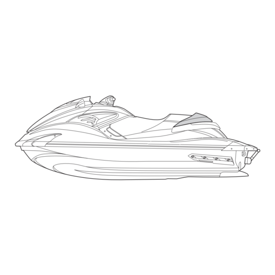
Model feature Model feature General feature The FZR (F3L) and FZS (F3K) have been developed based on the FZR (F2R) and FZS (F2C) and a newly designed high output, 1.8L supercharged engine and a larger jet pump are adopted. The new 6EV engine, developed based on the 6AN engine, is fitted with a high-performance super- charger, large-sized air cooler, and high-efficiency oil cooler to achieve higher engine output. -
Page 6: Model Equipment Comparison Table
Model equipment comparison table Model Total length 3.37 m (132.7 in) Width 1.23 m (48.4 in) Dry weight 375 kg (827 lb) 377 kg (831 lb) Seats *1 2- seater 3-seater *1: The rear seats “1” and handgrips “2” for the FZR and FZS have different shape. A. -
Page 7: Technical Tips
Technical tips Technical tips Engine control The ECM controls ignition timing and fuel injection with information received from the sensors and switches installed on the engine as well as utilizing the base map saved in the ECM. Part name Function Cam position sensor Detects the rotational position of the camshaft. - Page 8 Part name Function 13 APS Detects the opening angle of the throttle lever. Detects when the handlebar is turned all the way to the right or 14 Steering sensor left and a load is applied. 15 Reverse sensor Detects the R position of the shift lever.
-
Page 9: Ecm Circuit Diagram
Technical tips ECM circuit diagram 28. Fuel injector #1 1. Rectifier 2. Stator regulator coil 29. Fuel injector #2 30. Fuel injector #3 4. Main relay 3. Fuse (20 A) 31. Fuel injector #4 5. Fuse (3 A) 32. Ignition coil #1 9. - Page 10 1. Rectifier regulator 26. APS 1 2. Stator coil 27. APS 2 3. Fuse (20 A) 28. Fuel injector #1 4. Main relay 29. Fuel injector #2 5. Fuse (3 A) 30. Fuel injector #3 6. Engine start switch 31. Fuel injector #4 7.
-
Page 11: Ecm Coupler Layout
Technical tips ECM coupler layout 1 2 3 4 5 6 7 27 28 29 30 31 32 33 54 55 56 57 58 59 60 61 8 9 10 11 12 13 34 35 36 37 38 39 62 63 64 65 66 67 68 69 14 15 16 17 18 19 40 41 42 43 44 45... - Page 12 Connecting part Color Connecting part Color ETV relay power Engine shut-off Red/Yellow White source (contact) switch Sensor ground Black/Orange — — TPS ground Black/Orange — — TPS 1 Pink — — TPS 2 Pink/Black — — TPS power source Orange —...
-
Page 13: Engine Control System
Technical tips Engine control system Item Condition Action Remarks Overheat • Engine temperature • Opening angle of the ETV Cancel: warning con- rises rapidly in a is regulated. • Stop the engine and wait trol short time. • Maximum engine speed is for 30 seconds or more. - Page 14 Item Condition Action Remarks ETV failure ETV failed, or open or • Opening angle of the ETV control short circuit is is fixed to the default detected in ETV opening angle. circuit. • Maximum engine speed is limited to approximately 2500 r/min.
- Page 15 Technical tips Item Condition Action Remarks Off-throttle Engine speed is sus- Slightly opens the throttle Throttle valve opening is steering tained at or above valve so that the watercraft controlled based on the (OTS) control 3000 r/min for several can maneuver. APS signal and the amount seconds and then of force applied to the...
-
Page 16: Self-Diagnosis
Self-diagnosis While the engine is running, the diagnostic codes “a” can be checked by pushing the “Hour Volt” but- ton “b” for approximately 8 seconds. TIP: Because the multifunction meter cannot display more than 1 diagnostic code even if there are multi- ple diagnostic codes, using the YDIS is recommended. - Page 17 Technical tips Diagnostic code output YDIS Code No. Item Multifunction Diagnosis meter Diagnosis record 124, 125, 126, ○ ○ ○ 127, 128 131, 132, 133, ○ ○ ○ 134, 135 ○ low octane fuel — — *1: Pickup coil *2: Intake air temperature sensor *3: Intake air pressure sensor *4: Thermo sensor *5: Reverse sensor...
-
Page 18: Power Unit
Power unit The new 6EV engine, developed based on the 6AN engine, produces higher output. The engine components have been improved in strength and optimized for better functionality to handle higher output. Major changes Description Larger diameter impeller (from ø82 mm to ø86 mm) High-performance super- Addition of fins (from 5 fins to 7 fins) to increase supercharged charger... -
Page 19: Jet Pump Unit
Technical tips Major changes Description Thermostat valve opening temperature has been changed to optimize engine temperature and to reduce pollutants in the Thermostat exhaust gases. Cooling passages through exhaust manifold and exhaust man- Cooling water passage ifold gasket have been optimized to reduce thermal load. Provides better anti-knock property to correspond to higher 10 Premium gasoline engine output. -
Page 20: Hull And Hood
Major changes Description To correspond to the higher output engine, the type of thrust Intermediate housing washer has been changed for better sealing performance. The diameter has been increased from 155 mm (6.10 in) to Impeller 160 mm (6.30 in) to correspond to the higher output engine. To correspond to the higher output engine, the number of recti- Impeller duct fying fins has been increased from 6 fins to 8 fins. -
Page 21: Lubrication System
Technical tips Lubrication system The 6EV engine features a wet-sump lubrication system. The oil cooler has been newly designed to regulate the engine temperature increase due to higher output. 1. Intake camshaft 13. Oil pump drive gear 2. Exhaust camshaft 14. -
Page 22: Hose Routing
Hose routing A. From flushing hose connector B. From transom plate C. To cooling water pilot outlet on port side D. To drain joint (transom plate) E. To drain joint F. To drain joint G. To cooling water pilot outlet on starboard side H. -
Page 23: Cooling Water Flow
Technical tips Cooling water flow A. From flushing hose connector B. From transom plate C. To cooling water pilot outlet on port side D. To drain joint E. To exhaust valve F. To cooling water pilot outlet on star- board side G. -
Page 24: Service Information
Service information Maintenance interval chart The following chart should be considered strictly as a guide to general maintenance intervals. Depending on the operating conditions, the maintenance intervals should be changed. Perform the pre-operation checks and post-operation checks before performing periodic maintenance. Initial Thereafter every Item... - Page 25 Service information Initial Thereafter every Item Operation 50 hours or 100 hours or 200 hours or 10 hours 12 months *1 12 months *1 24 months *1 Check for exhaust leak- ○ Exhaust system age, and check hoses and clamps Check breather hose ○...
-
Page 26: Specifications
Width 1230 mm (48.4 in) Height 1160 mm (45.7 in) Dry weight GX1800 375 kg (827 lb) GX1800A 377 kg (831 lb) Maximum people on board GX1800 2 person GX1800A 3 person Maximum load capacity GX1800 160 kg (353 lb) - Page 27 Specifications Jet pump unit Jet pump type Axial flow, single stage Impeller rotation Counterclockwise Impeller diameter 160 mm (6.30 in) Number of impeller blades 17.0 ° Impeller pitch angle Transmission Direct drive from engine 24.0+24.0 ° Jet thrust nozzle angle Trim adjusting system Manual 5 position -10, -5, 0, 5, 10 °...
-
Page 28: Wiring Diagram
Wiring diagram How to use the wiring diagram Legend symbols in the wiring diagrams Double color wire No wire connector Color code : Pink : Black : Pink/Black : Brown : Pink/Green : Black/Blue : Pink/Red : Black/Orange : Pink/White : Black/Red Pu/B : Purple/Black... - Page 30 Nov. 2013 ABE...
- Page 31 FZR, FZS Dual analog meter Remote control Main and receiver fuel pump Hour Volt button Reverse relay switch relay R Br Buzzer FREE PUSH PULL Fuse box Starter motor Br Br FREE Fuel sender Left handlebar PUSH switch Battery Speed sensor 1 4 8 12 1 8 14 20 3 7 11 14...
- Page 32 FZR, FZS A. To entry box B. Antenna a. Fuse (30 A) (battery) b. Fuse (20 A) (main and fuel pump relay) c. Fuse (10 A) (ETV relay) d. Fuse (10 A) (main and fuel pump relay) e. Fuse (3 A) (remote control receiver) f.