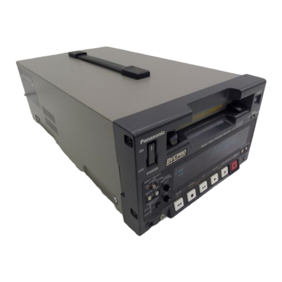
Panasonic AJ-D230H Operating Instructions Manual
Digital video cassette recorder
Hide thumbs
Also See for AJ-D230H:
- Operating instructions manual (40 pages) ,
- Service manual (104 pages)

Related Manuals for Panasonic AJ-D230H


Summary of Contents for Panasonic AJ-D230H
-
Page 1: Operating Instructions
Digital Video Cassette Recorder Operating Instructions Printed in Japan VQT7626 S0698W... - Page 2 IMPORTANT “Unauthorized recording of television programs, video tapes and other materials may infringe the right of copyright owners and be contrary to copyright laws.” CAUTION: TO REDUCE THE RISK OF ELECTRIC SHOCK, DO NOT REMOVE COVER (OR BACK). NO USER SERVICEABLE PARTS INSIDE. REFER TO SERVICING TO QUALIFIED SERVICE PERSONNEL.
-
Page 3: Table Of Contents
Table of Contents Introduction Features Controls and Their Functions Front panel Connector section Tapes Operation Switching on the power and inserting the cassette Stop mode Recording Pause/still recording (back-space assemble recording) Playback Cue and Review Still-picture playback Frame advance Sound selection Repeat playback Time Code and User’... - Page 4 Table of Contents RS-232C Interface 1. Hardware specifications 1) Interface specifications 2) Communication parameters 2. Software specifications 1) External interface specifications 2) Sending format (from personal computer to VTR) 3) Receiving format (from VTR to personal computer) 4) Command list Error Messages Video Head Cleaning Condensation...
-
Page 5: Introduction
An interactive format is used to perform the unit’ s settings while monitoring the menus on the screen of the TV monitor. The model AJ-D230H is provided with an RS-232C connector as a standard feature to enable the unit to be operated by remote control from a computer. -
Page 6: Controls And Their Functions
Controls and Their Functions Front Panel Counter display area... - Page 7 Controls and Their Functions Front panel POWER switch When the ON side is pressed, the power is turned on, and the counter display area lights. Cassette slot A news gathering cassette, general-purpose cassette or consumer-use cassette with an adaptor is loaded through this slot. Consumer-use cassettes can be played back only.
- Page 8 Controls and Their Functions Headphone jack When stereo headphones are connected here, the recording or playback sound can be monitored “ through the headphones. Volume control This is for adjusting the headphones volume. Volume recording level control This is for adjusting the PCM audio signal CH1/CH2 recording level.
-
Page 9: Connector Section
Controls and Their Functions Connector section... - Page 10 Controls and Their Functions Connector section AC IN connector Use the power cord supplied to connect this connector to the power outlet. SIGNAL GND terminal This is connected to the signal ground terminal on the unit connected in order to reduce the noise.
-
Page 11: Tapes
(option) is obtained. Consumer-use cassette Use of Panasonic consumer DV cassette tape is recommended. (S size cassette) Note that inserting a cassette tape without using the cassette adaptor can damage the unit. -
Page 12: Operation
Operation Switching on the power and inserting the cassette Before attempting to operate the unit, make sure that it has been connected properly. Switch on the power. Insert the cassette tape. Insert the cassette tape into its prescribed position without forcing it in any way. Check that the STOP lamp has lighted. -
Page 13: Stop Mode
Operation Stop mode The unit is set to the stop mode when the STOP button is pressed. The STOP lamp lights and the tape stops traveling. In order to protect the tape, the unit is set to the tape protection mode after the period of time set in the “... -
Page 14: Recording
Operation Recording Set the accidental erasure prevention tab on the cassette tape to “recording,” and insert the tape. Press the STOP button to set the unit to the stop mode. Check that the REC INH lamp is off. Selecting the video and audio input signals and adjusting the audio signal level Selecting the video and audio input signals Connect the signals which are to be recorded. -
Page 15: Pause/Still Recording (Back-Space Assemble Recording)
Operation Pause/still recording (back-space assemble recording) Press the PAUSE/STILL button while the cassette tape is playing. If the “ AUTO BACK” set-up menu item has been set to ON, the tape will be rewound for 1 or 2 seconds starting at the position where the PAUSE/STILL button was pressed. (See page 25) Press the REC button to set the unit to the REC PAUSE mode. -
Page 16: Still-Picture Playback
Operation Frame advance The tape is advanced or reversed frame by frame when the FF or REW button is pressed during playback. No sound is heard during frame advance or reverse. Sound selection Use the AUDIO OUT SELECT button to select the desired sound. By pressing the AUDIO OUT SELECT button, the mode for the audio output is selected in the sequence shown below. -
Page 17: Repeat Playback
Operation Repeat playback Setting the BEGIN and END points [Menu mode] Set the VTR to the menu mode. (Set the LOCAL/MENU/REMOTE switch to the MENU position.) Select the “BEGIN/END PRESET” set-up menu item, and press the MODE (REW) button. (See page 27) Select TC or CTL using the COUNTER button. - Page 18 Operation Setting the BEGIN and END points [Front panel] Set the VTR to the local mode. (Set the LOCAL/MENU/REMOTE switch to the LOCAL position.) Press the BEGIN or END button on the front panel to set the current position as the BEGIN or END point.
-
Page 19: Time Code And User' S Bit
Time Code and User’ s Bit Time code The time code signal generated by the time code generator is recorded on the tape as a time code, it is read out by the time code (signal) reader, and used to display the absolute position of the tape in increments of hours, minutes, seconds and frames. -
Page 20: Setting The Time Code
Time Code and User’ s Bit Setting the time code Set the VTR to the menu mode. (Set the LOCAL/MENU/REMOTE switch to the MENU position.) Select the “TC PRESET” set-up menu item, and press the MODE (REW) button. (See page 28) Select the digit (flashing display) in which the change is to be made using the UP (FF) and DOWN (STOP) buttons. -
Page 21: Time Code And User' S Bit Playback
Time Code and User’ s Bit Time code and user’ s bit playback Set the VTR to the STOP mode. Set to TC or UB using the COUNTER button. : The time code is displayed. UB : The user’ s bit is displayed. When the time code can no longer be read, interpolation is provided by the control signal if the COUNTER button is set to the CTL position. -
Page 22: Superimposed Display Screens
Superimposed Display Screens When the MONITOR OUT connector has been connected to the TV monitor, the abbreviations corresponding to the control signal, time code, etc. are displayed on the TV monitor. Abbreviation TV monitor Characters displayed The background of the characters superimposed onto the display can be changed using the “... -
Page 23: Set-Up (Default Settings)
Set-up (Default Settings) The VTR’ s major settings are performed by making selections using a menu system. The set-up menus appear on the TV monitor when it is connected to the MONITOR OUT connector. Changing a setting Set the VTR to the menu mode. (Set the LOCAL/MENU/REMOTE switch to the MENU position.) Select the item to be set using the UP (FF) and DOWN (STOP) buttons. -
Page 24: Set-Up Menus
Set-up Menus BASIC menu Item S u p e r i m p o s e d d i s p l a y DISPLAY SEL 0000 0001 0002 CHARA H-POS 0000 0001 0003 0007 CHARA V-POS 0000 0001 0003 0007 0000 CHARA TYPE... -
Page 25: Operation Menu
Set-up Menus OPERATION menu Item S u p e r i m p o s e d d i s p l a y 1 0 0 LOCAL 0000 ENABLE 0001 1 0 1 TAPE TIMER 0000 0001 1 0 2 S/F/R EE SEL 0000 0001 1 0 3 WIDE MODE 0000... -
Page 26: Interface Menu
Set-up Menus OPERATION menu Item S u p e r i m p o s e d d i s p l a y 108 FORMAT SEL 0000 0001 0002 <Note> The cassette tape is played back in one of the modes listed below depending on the tape type and settings used. -
Page 27: Memory Mode Menu
Set-up Menus MEMORY MODE menu Item S u p e r i m p o s e d d i s p l a y 0000 300 MEMORY 0001 MODE 0002 0003 301 BGN/END PRESET The underlined number and item are the factory settings. TAPE PROTECT menu Item S u p e r i m p o s e d... -
Page 28: Time Code Menu
Set-up Menus TIME CODE menu Item S u p e r i m p o s e d d i s p l a y VITC POS-1 0000 0001 0006 0010 0000 VITC POS-2 0001 0008 0010 0000 VITC BLANK 0001 0000 TCG REGEN... -
Page 29: Video Menu
Set-up Menus VIDEO menu Item S u p e r i m p o s e d display VIDEO MODE 0000 0001 0000 V-MUTE SEL 0001 602 CC (F1) BLANK 0000 0001 603 CC (F2) BLANK 0000 0001 604 STD/NSTD SEL 0000 0001 605 FREEZE SEL 0000... -
Page 30: Audio Menu
Set-up Menus AUDIO menu Item Superimposed d i s p l a y SEARCH CUE 7 0 1 DV PBATT 7 0 2 PB MUTE AUDIO REC IN 0000 The underlined number and item are the factory settings. RS-232C Interface The following functions can be controlled by using the RS-232C interface. -
Page 31: Hardware Specifications
RS-232C Interface 1. Hardware specifications 1) Interface specifications Connector: D-SUB, 25P, DCE specifications (straight cable supported) Signal Pin No. SD (TXD) RD (RXD) RS (RTS) CD (CTS) DR (DSR) ER (DTR) Example of wiring connections Personal computer Frame FG SD (TXD) RD (RXD) RS (RTS) CD (CTS) -
Page 32: Software Specifications
RS-232C Interface 2. Software specifications 1) External interface specifications Asynchronous, full duplex Communication system 1200/2400/4800/9600/19200 Baud rate 8 bit/7 bit Bit length 1 bit/2 bit Stop bit NONE/ODD/EVEN Parity The factory settings are 9600 bps, 8 bits, 1 stop bit, and none for the parity. 2) Sending format (from personal computer to VTR) Data format [STX] [discrimination] [:] [data] [ETX]... - Page 33 RS-232C Interface 2. Next, after [ACK] is returned because communication was error-free, data is returned in the following format by the operation of the VTR. 1) The response data (return data) format when the command from the personal computer was received properly by the VTR is as follows.
-
Page 34: Command List
RS-232C Interface 4) Command list Key commands S e n d Description of operation command All the VTR’ s operations are stopped, and the VTR is set to (STOP) the stop mode. Cassette is ejected. (EJECT) Playback is commenced. (PLAY) The tape is rewound. - Page 35 RS-232C Interface Counter sense command Send Description of operation command This command inquires as to the current value of the (COUNTER counter. The CTL counter value or TCR value is returned. SENSE) The counter keys on the front panel or the menu is used to select the CTL counter and TCR values.
-
Page 36: Error Messages
ERROR MESSAGES When trouble has occurred in the VTR, one of the following messages appears on the tape counter. The VTR stops operating when any of the error numbers except E-00 and E-01 is displayed. Error No. — d — Condensation has formed. -
Page 37: Video Head Cleaning
This VTR comes with an auto head cleaning function which automatically reduces the amount of dirt on the heads. However, to ensure the highest reliability, we recommend that you clean the video heads every day. Use the cleaning fluid designated by Panasonic. Checking the hour meter Set the VTR to the remote mode. -
Page 38: Specifications
SPECIFICATIONS GENERAL Power supply: Power consumption: Ambient operating temperature: Ambient operating humidity: Weight: Dimensions (W × H × D): Recording format: Recording tracks: Time code: Digital audio: Cue track: Control (CTL): Tape speed: Recording time: Tape used: FF/REW time: VIDEO (Digital video) Sampling frequency: Quantizing:... - Page 39 Division of Matsushita Electric Corporation of America Executive Office One Panasonic Way (4B-7) Secaucus, NJ 07094 Service Centers Eastern: One Panasonic Way, Panazip (2A-4), Secaucus, NJ 07094 (201)-348-7677 Fax (201)-348-7511 Southern: 1225 Northbrook Parkway, Suite #170, Suwanee, GA 30174 (770)-338-6855 Fax (770)-338-6656 Western: 4001 West Alameda Ave., Suite 100, Burbank, CA 91505...