Table of Contents
Advertisement
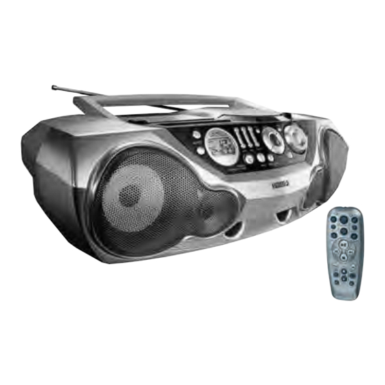
CD Stereo Radio Recorder
TABLE OF CONTENTS
Handling Chip Components and Safety ..........................1 - 1
Technical Specification & Service tools...........................2 - 1
Service Measurement......................................................2 - 2
Connections and controls.......................................3 - 1..3 - 2
Disassembly Diagram......................................................4 - 1
CD Service Test program .....................................4 - 2 .. 4 - 3
Block Diagram .................................................................5 - 1
Wiring Diagram ................................................................5 - 2
Circuit diagram ........................................................6 - 1
Front part.................................................................6 - 2
Tuner part................................................................7 - 1
Tuner adjustment ....................................................7 - 2
©
Copyright 2001 Philips Consumer Electronics B.V. Eindhoven, The Netherlands
All rights reserved. No part of this publication may be reproduced, stored in a retrieval
system or transmitted, in any form or by any means, electronic, mechanical, photocopying,
or otherwise without the prior permission of Philips.
Published by YT 0206 Service Audio
Printed in The Netherlands
Subject to modification
CD part 2 ................................................................8 - 2
Tape part .................................................................9 - 1
Audio/supply part.....................................................9 - 2
Layout diagram (copper side)................................10 - 1
Layout diagram (component side).........................10 - 2
Exploded view - cabinet.................................................11 - 1
Exploded view - tape deck ............................................11 - 2
Tape deck adjustment ...................................................11 - 2
Mechanical partslist .......................................................11 - 2
Electrical partslist ...........................................12 - 1 .. 12 - 11
AZ 2040
AZ 2045
all versions
CLASS 1
LASER PRODUCT
© 3140 785 22910
Advertisement
Table of Contents

Related Manuals for Philips AZ 2040


Summary of Contents for Philips AZ 2040
-
Page 1: Table Of Contents
LASER PRODUCT © Copyright 2001 Philips Consumer Electronics B.V. Eindhoven, The Netherlands All rights reserved. No part of this publication may be reproduced, stored in a retrieval system or transmitted, in any form or by any means, electronic, mechanical, photocopying, or otherwise without the prior permission of Philips. - Page 2 1 - 1 HANDLING CHIP COMPONENTS © ñ WARNING WAARSCHUWING All ICs and many other semiconductors are susceptible to Alle IC´s en vele andere halfgeleiders zijn gevoelig voor electrostatic discharges (ESD). Careless handling during electrostatische ontladingen (ESD). repair can reduce life drastically. Onzorgvuldig behandelen tijdens reparatie kan de levensduur When repairing, make sure that you are connected with the drastisch doen vermindern.
-
Page 3: Technical Specifications
2 - 1 TECHNICAL SPECIFICATIONS GENERAL SPECIFICATIONS Mains voltage -/00/05/14 : 230 V TUNER - AM SECTION -/01 : 120 / 230 V /10 : 240V Tuning range MW : 531 - 1602 kHz -/17 : 120 V -/17 : 530 - 1700 kHz Mains freq. -
Page 4: Service Measurement
2 - 2 SERVICE MEASUREMENT Bandpass Tuner SW LF Voltmeter 250Hz-15kHz Aerial replacement e.g. PM2534 e.g. 7122 707 48001 RF Generator Capacitor e.g. PM5326 S/N and distortion meter e.g. Sound Technology ST1700B To avoid atmospheric interference all AM-measurements have to be carried out in a Faraday´s cage. Use a bandpass filter (or at least a high pass filter with 250Hz) to eliminate hum (50Hz, 100Hz). -
Page 5: Connections And Controls
3 - 1 CONNECTIONS AND CONTROLS TOP AND FRONT PANELS REMOTE CONTROL (for AZ2045 only) 1 SOURCE – selects CD/ TUNER / TAPE function 1 CD – selects CD sound source 2 y – power on/ off switch 2 y – switches the set off 3 Display –... - Page 6 • When inserting new batteries, do not try to mix old batteries with the new ones. • Batteries contain chemical substances, so they should be disposed of properly. For more information on operation instruction please visit Philips Audio internet site : http://www.audio.philips.com...
-
Page 7: Disassembly Diagram
4 - 1 4 - 1 DISASSEMBLY DIAGRAM D. REMOVE DECK MECHANISM - REMOVE SCREWS D6 (3X8) 4 PCS. A. REMOVE FRONT CABINET ASSEMBLY - REMOVE CASSETTE DECK - REMOVE SCREWS A1 (3X20) 9 PCS. - REMOVE SCREWS D7 (2.5X10) 4 PCS. A1 (x9) - REMOVE SCREW A2 (3X10) 1 PC - REMOVE CD DECK... -
Page 8: Cd Service Test Program
4 - 2 4 - 2 SERVICE TEST PROGRAM STOP button pressed in any step returns to begin of Service Testprogram. To leave Service Testprogram press POWER to switch off. Door switch is ignored → CD door can be opened. To enter CD Service CD TEST To enter CD Service... - Page 9 4 - 3 4 - 3 Abbreviations and Pin-description of CD ICs Abbreviations and Pin-description of CD ICs Abbreviations and Pin-description of CD Ics Abbreviations and Pin-description of CD Ics SERVO PROCESSOR SAA7325H SERVO PROCESSOR SAA7325H SYMBOL DESCRIPTION SYMBOL DESCRIPTION HFREF comparator common mode input microcontroller interface R/W and load control line input (4-wire bus mode)
-
Page 10: Block Diagram
5 - 1 5 - 1 GRAM BLOCK DIAGRAM Ripple Filter LCD DISPLAY ECO MTF Sound Processor with Source Selector, LAYOUT 3 Bands EQ, DBB and ALC CELL 4.19MHz A_on ECO6 TMP86CH21 LAYOUT Mute CELL Power Mute Speaker Amp. Ctrl *Optional CD99 LAYOUT... -
Page 11: Wiring Diagram
5 - 2 5 - 2 WIRING DIAGRAM TAPE MECHANISM CD DOOR SWITCH 1404 9V BATTERY MOTOR 1403 MECHANISM DIPMATE ON/OFF SW 8802 PLAY SW REC/PLAY HEAD 8202 TRANSFORMER VOLTAGE SELECTOR COMBI BOARD /01,/11,/19 1011 110-127V 220-240V 65MM 8701 BATTERIES 8702 8703 BLUE... -
Page 12: Key Board Circuit Diagram
6 - 1 6 - 1 KEY BOARD - CIRCUIT DIAGRAM CP1 F8 1500 D9 1501 D8 1502 D7 1503 D6 1504 D5 REMOTE CONTROL 1505 D4 For AZ2045 only 1506 D3 1507 D2 1508 D1 1509 E9 7500 1510 E8 TSOP2236 T500 1511 E7... -
Page 13: Combi Board - Circuit Diagram Front Part
6 - 2 6 - 2 COMBI BOARD - CIRCUIT DIAGRAM (FRONT PART) 1400 H6 3492 K15 1401 A15 3493 J6 1402 G17 3494 K5 1403 H19 3495 B14 1404 I19 3496 B14 +VAref 1406 A16 3522 D17 2400 E14 3523 D16 3445 2401 E14... -
Page 14: Tuner Part
7 - 1 7 - 1 COMBI BOARD - CIRCUIT DIAGRAM (TUNER PART) 1105 A2 4104 L7 4105 B12 1121 H20 1122 G20 4109 D5 2101 B5 4110 D5 TUNER BOARD ECO6 /PORTABLE AUDIO 2103 D9 5102 G4 AM-IF1 2104 A4 5103 H3 VERSION PROGRAMMING COMPONETS 5111... -
Page 15: Tuner Adjustment
7 - 2 7 - 2 TUNER BOARD ECO6 - LAYOUT DIAGRAM TUNER ADJUSTMENT TABLE ( ECO6 FM/MW- and FM/MW/LW - versions with ferrite antenna) Waverange Input frequency Input Tuned to Adjust Output Scope/Voltmeter 1105 B7 2106 D6 2129 C5 2155 C5 2191 A2 5102 D7... -
Page 16: Combi Board - Circuit Diagram Cd Part 1
8 - 1 8 - 1 COMBI BOARD - CIRCUIT DIAGRAM (CD PART 1) 1800 E2 2807 F5 2815 G14 2823 B15 2831 I16 2839 K6 2864 E6 2875 E7 3800 B3 3808 A3 3816 F7 3824 G13 3835 C20 3844 I18 3852 H7 3860 K7... -
Page 17: Cd Part 2
8 - 2 8 - 2 COMBI BOARD - CIRCUIT DIAGRAM (CD PART 2) 1700 D1 1707-H E5 2708 A2 2715 B5 2726 D5 2733 E9 2772 C8 3720 C6 3730 D8 3738 C9 3749 B1 3774 C4 7705 B3 9758 E9 T707 B7 T714 E10... -
Page 18: Tape Part
9 - 1 9 - 1 COMBI BOARD - CIRCUIT DIAGRAM (TAPE PART) 1700 D1 1707-H E5 2708 A2 2715 B5 2726 D5 2733 E9 2772 C8 3720 C6 3730 D8 3738 C9 3749 B1 3774 C4 7705 B3 9758 E9 T707 B7 T714 E10 T721 A10... -
Page 19: Audio/Supply Part
9 - 2 9 - 2 COMBI BOARD - CIRCUIT DIAGRAM (AUDIO/SUPPLY PART) 1251 H4 3289 E2 1252 H4 3290 E2 1253 D14 3291 G7 1254 H4 3293 G7 1256 E14 3295 G7 TO CD99 layout cell 1257 C14 3296 B1 1258 I4 3297 B1 2251 A2... - Page 20 10 - 1 10 - 1 COMBI BOARD - LAYOUT DIAGRAM (COPPER SIDE) 1517 1514 1512 1510 BASS+ MID+ TREBLE+ VOLUME POWER 1509 1500 1518 CD MODE PROGRAM 7500 TUNE DOWN TUNE UP SOURCE 1505 1501 BASS- MID- PLAY 1516 1515 1513 1503...
-
Page 21: Combi Board - Layout Diagram
10 - 2 10 - 2 COMBI BOARD - LAYOUT DIAGRAM (COMPONENT SIDE) 1517 1514 1512 1510 BASS+ MID+ TREBLE+ 1509 VOLUME POWER 1500 1518 CD MODE PROGRAM TUNE DOWN TUNE UP 7500 SOURCE 1505 1501 BASS- MID- PLAY 1516 1515 1513 1503... - Page 22 11 - 1 11 - 1 EXPLODED VIEW DIAGRAM - CABINET (9x) 1011 (2x) 1006 1005 (4x) (13x) 1404 (4x) SCREW LIST : (4x) 418 (x2) M2x6 T2 x 8 (5x) T2 x 10 T2.5 x 10 (4x) 1007 (6x) T3 x 8 T3 x 10 T3 x 12...
-
Page 23: Mechanical Partslist
11 - 2 11 - 2 EXPLODED VIEW DIAGRAM - TAPE DECK MECHANICAL PARTSLIST - CABINET 3140 117 61760 FRONT CABINET ASS'Y 3103 309 05360 CD DA11B1N DRIVE ASSY 3140 117 63260 FRONT CABINET ASS'Y (AZ2045/17) 3140 111 01120 SPRING-CASS.DOOR 3140 117 62050 CD PANEL - FRONT ASS'Y (AZ2045) 3140 111 01130... - Page 24 12 - 1 12 - 1 ELECTRICAL PARTSLIST - FRONT AND KEY BOARD ELECTRICAL PARTSLIST - FRONT AND KEY BOARD - MISCELLANEOUS - - CAPACITORS - - RESISTORS - - RESISTORS - 1401 4822 265 11531 FFC SOCKET 9P HOR. 2433 4822 124 40207 100µF 20% 25V...
-
Page 25: Electrical Partslist
12 - 2 ELECTRICAL PARTSLIST - FRONT AND KEY BOARD - COILS & FILTERS - 5409 2422 549 44393 IND FXD 2,7K 100MHZ 5410 2422 549 44393 IND FXD 2,7K 100MHZ 5411 2422 549 44393 IND FXD 2,7K 100MHZ 5412 2422 549 44393 IND FXD 2,7K 100MHZ 5413... - Page 26 12 - 3 ELECTRICAL PARTSLIST - COMBI BOARD- TUNER PART - CAPACITORS - - CAPACITORS - 2101 4822 122 33777 47pF 5% NP0 63V 2188 5322 126 11583 10nF 10% X7R 50V 2103 5322 126 11578 1nF 10% X7R 50V 2189 4822 126 13879 220nF +80-20% 16V...
- Page 27 12 - 4 ELECTRICAL PARTSLIST - COMBI BOARD- TUNER PART - RESISTORS - - DIODES - 3189 4822 051 30223 22K 5% 0,062W 6103 5322 130 34337 BAV99 3190 4822 051 30103 10K 5% 0,062W 6105 4822 130 83075 HN1V02H-B 3191 4822 051 30472 4,7K 5% 0,062W...
- Page 28 12 - 5 ELECTRICAL PARTSLIST - COMBI BOARD- CD PART - CAPACITORS - - CAPACITORS - 2801 4822 124 40433 47µF 20% 25V 2857 4822 124 12362 47µ 4V 20% 2802 4822 124 40433 47µF 20% 25V 2860 5322 116 80853 560pF 5% NP0 63V 2803 4822 126 14226...
- Page 29 12 - 6 ELECTRICAL PARTSLIST - COMBI BOARD- CD PART - RESISTORS - - RESISTORS - 3830 4822 051 30472 4,7K 5% 0,062W 3888 4822 051 20472 4,7K 5% 0,1W 3835 4822 051 30223 22K 5% 0,062W 3890 4822 117 10837 100K 1% 0.1W 3836 4822 117 10833...
- Page 30 12 - 7 ELECTRICAL PARTSLIST - COMBI BOARD- CD PART - COILS & FILTERS - 1810 2422 540 98519 RES CER 8,467MHZ 5803 4822 157 11231 1µH 5804 2422 549 44393 IND FXD 100MHZ 2K7 - DIODES - 6877 4822 130 11564 UDZ3.9B - IC &...
- Page 31 12 - 8 ELECTRICAL PARTSLIST - COMBI BOARD- TAPE PART - MISCELLANEOUS - - RESISTORS - 1707 4822 277 11504 SWITCH-PUSH 3733 4822 051 30475 4,7M 5% 0,062W 5701 4822 157 10371 COIL BIAS OSC 3734 4822 051 30103 10K 5% 0,062W 3737 4822 051 30103 10K 5% 0,062W...
- Page 32 12 - 9 ELECTRICAL PARTSLIST - COMBI BOARD - AF PART - MISCELLANEOUS - - CAPACITORS - 1254 ! 2422 086 10783 FUSE 2A 250V IEC 2301 4822 126 11585 22nF +80-20% 25V 1254 ! 4822 253 10128 FUSE 2A 250V UL 2302 4822 126 11585 22nF +80-20% 25V...
- Page 33 12 - 10 ELECTRICAL PARTSLIST - COMBI BOARD - AF PART - IC & TRANSISTORS - 7263 4822 130 60511 BC847B 7265 4822 130 42804 BC817-25 7266 4822 130 42804 BC817-25 7267 4822 130 41246 BC327-25 7268 4822 130 41246 BC327-25 7269 4822 130 60373...
- Page 34 12 - 11 ELECTRICAL PARTSLIST - COMBI BOARD - AF PART - IC & TRANSISTORS - 7263 4822 130 60511 BC847B 7265 4822 130 42804 BC817-25 7266 4822 130 42804 BC817-25 7267 4822 130 41246 BC327-25 7268 4822 130 41246 BC327-25 7269 4822 130 60373...