
Related Manuals for Toro 22333


Summary of Contents for Toro 22333
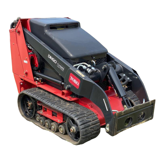
- Page 1 Form No. 3357-573 Rev A TX 525 Compact Utility Loader Model No. 22333—Serial No. 270000001 and Up Model No. 22334—Serial No. 270000001 and Up G004222 Register your product at www.Toro.com Original Instructions (EN)
-
Page 2: Introduction
If you require a spark arrestor, contact your Authorized Service Dealer. Figure 1 Genuine Toro spark arresters are approved by the 1. Safety alert symbol USDA Forestry Service. Important: It is a violation of California... -
Page 3: Table Of Contents
Contents Fuel System Maintenance ......34 Checking the Fuel Lines and Connections...... 34 Introduction ............2 Draining the Fuel Filter/Water Safety ..............4 Separator......34 Safe Operating Practices ...... 4 Replacing the Fuel Filter Sound Pressure........7 Canister......35 Sound Power ........7 Draining the Fuel Tank ...... -
Page 4: Safety
Safety hearing protection. Long hair, loose clothing or jewelry may get tangled in moving parts. Improper use or maintenance by the operator • Inspect the area where the equipment is to be or owner can result in injury. To reduce used and remove all objects such as rocks, toys, and wire which can be thrown by the machine. - Page 5 • Ensure that you operate the traction unit in traction unit. Tall grass can hide obstacles. areas where there are no obstacles in close • Use only Toro-approved attachments. proximity to the operator. Failure to maintain Attachments can change the stability and...
- Page 6 Reconnect positive first and negative last. • Use only genuine Toro replacement parts to ensure that original standards are maintained. • Keep hands and feet away from moving parts. If possible, do not make adjustments with the engine running.
-
Page 7: Sound Pressure
• Battery acid is poisonous and can cause burns. Avoid contact with skin, eyes, and clothing. Protect your face, eyes, and clothing when working with a battery. • Battery gases can explode. Keep cigarettes, sparks and flames away from the battery. •... -
Page 8: Slope Chart
Slope Chart... -
Page 9: Safety And Instructional Decals
Safety and Instructional Decals Safety decals and instructions are easily visible to the operator and are located near any area of potential danger. Replace any decal that is damaged or lost. 112-2540 5. Hour meter 13. Fast 1. Operator’s Manual location 9. - Page 10 100-8821 93-6686 1. Crushing hazard and cutting hazard of hand—stay a safe 1. Hydraulic oil distance from the front of the traction unit when the loader 2. Read the Operator’s Manual. arms are raised. 108-4636 1. Auxiliary hydraulics 3. Forward 2.
- Page 11 Battery Symbols Some or all of these symbols are on your battery 1. Explosion hazard 6. Keep bystanders a safe distance from the battery. 104-9958 2. No re, open ame, or 7. Wear eye protection; smoking. explosive gases can cause 1.
-
Page 12: Setup
Setup Step Activating the Battery Parts needed for this step: Bulk electrolyte with 1.265 specic gravity ounces (Purchase from a battery supply outlet.) Procedure Warning CALIFORNIA Proposition 65 Warning Figure 2 1. Battery access panel 4. Washer Battery posts, terminals, and related 2. -
Page 13: Charging The Battery
Figure 4 G003792 Figure 6 1. Positive post 3. Charger red (+) wire 5. Wait five to ten minutes after filling the battery 2. Negative post 4. Charger black (—) wire cells. Add electrolyte, if necessary, until the electrolyte level is up to the upper line on the battery case. -
Page 14: Checking Fluid Levels
Figure 7 1. Battery access panel 4. Washer 2. Battery clamp 5. Battery 3. Bolt Step Checking Fluid Levels No Parts Required Procedure Before starting the engine for the first time, check the engine oil and hydraulic fluid levels. Refer to Operation for more information. -
Page 15: Product Overview
Product Overview Figure 8 1. Road wheels 4. Loader arms 7. Mount plate 10. Tie-down/lift loop 11. Rear access cover 2. Track 5. Hood 8. Reverse safety plate 3. Lift cylinder 6. Auxiliary hydraulic couplers 9. Control panel... -
Page 16: Controls
Controls Traction Control To move forward, move the traction control Become familiar with all the controls (Figure 9) forward. To move rearward, move the traction before you start the engine and operate the traction control rearward (Figure 10). unit. To turn, rotate the traction control in the desired direction (Figure 10). -
Page 17: Parking Brake Lever
Auxiliary Hydraulics Lever To operate a hydraulic attachment in the forward direction, rotate the auxiliary hydraulics lever rearward and pull it down to the reference bar (Figure 13, number 1). To operate a hydraulic attachment in reverse direction, rotate the hydraulics lever rearward, then move it left into the upper slot (Figure 13, number If you release the lever while in the forward Figure 11... - Page 18 Figure 14 To release the brake, push the lever forward and Figure 15 then right, into the notch. 1. Engine oil pressure light 4. Battery charge indicator light Fuel Gauge 2. Engine coolant 5. Glow plug light temperature light 3. Glow plug switch This gauge measures the amount of fuel in the fuel tank.
-
Page 19: Specifications
66 inches (168 cm) Attachments/Accessories A selection of Toro approved attachments and accessories are available for use with the machine to enhance and expand its capabilities. Contact your Authorized Service Dealer or Distributor or go to www.Toro.com for a list of all approved attachments and accessories. -
Page 20: Stability Data
Front Uphill rating of B, a Rear Uphill rating of D, and a Side Uphill rating of C, then you could drive forward up a 19° slope, rearward up a 12° slope, or sideways on a 14° slope, as listed in the following table. Model 22333 Maximum Recommended Slope when Operating with:... -
Page 21: Operation
Operation Under certain conditions, diesel fuel and Note: Determine the left and right sides of the fuel vapors are highly flammable and machine from the normal operating position. explosive. A fire or explosion from fuel Important: Before operating, check the can burn you and others and can cause fuel and oil level, and remove debris from the property damage. -
Page 22: Checking The Hydraulic Fluid Level
2. Park the traction unit on a level surface, lower the loader arms, and fully retract the tilt cylinder. 3. Stop the engine, remove the key, and allow the engine to cool. 4. Open the hood. 5. Clean the area around the filler neck of the hydraulic tank (Figure 18). -
Page 23: Checking, Adding, And Bleeding
If the engine has been running, the pressurized, hot coolant can escape and cause severe burns. • Do not remove the radiator cap when the engine is hot. Always allow the engine to cool at least 15 minutes or until the radiator cap is cool enough to touch without burning your hand before removing the radiator cap. -
Page 24: Bleeding The Fuel System
E. Pour coolant into the coolant filler neck until the coolant begins to come out of the top coolant bleed valve (Figure 21). F. Close the top coolant bleed valve (Figure 21). G. Pour coolant into the coolant filler neck until the coolant level comes into the filler neck (Figure 21). -
Page 25: Starting And Stopping The Engine
2. Open the hood. 5. Turn the ignition key to the Start position. When the engines starts, release the key. 3. Open the air bleed screw on the fuel injection pump (Figure 22). Important: Do not engage the starter for more than 10 seconds at a time. If the engine fails to start, allow a 30 second cool-down period between attempts. -
Page 26: Moving A Non-Functioning
Moving a Non-functioning 2. Raise the loader arms to the fully raised Traction Unit position. 3. Stop the engine. Important: Do not tow or pull the traction 4. Remove the hairpin cotter and clevis pin unit without first opening the tow valves, or securing the cylinder lock to the loader arm the hydraulic system will be damaged. -
Page 27: Using Attachments
Check the Installing an Attachment receiver plate and clean it if necessary. Important: Use only Toro-approved attachments. Attachments can change the stability and the operating characteristics of the traction unit. The warranty of the traction unit may be voided if used with unapproved attachments. -
Page 28: Securing The Traction Unit For Transport
Connecting the Hydraulic Hoses 8. Confirm that the connection is secure by pulling on the hoses. If the attachment requires hydraulics for operation, 9. Move the auxiliary hydraulics lever to neutral. connect the hydraulic hoses as follows: 1. Stop the engine. Removing an Attachment 2. -
Page 29: Maintenance
Maintenance Note: Determine the left and right sides of the machine from the normal operating position. Recommended Maintenance Schedule(s) Maintenance Service Maintenance Procedure Interval After the rst 8 operating • Replace the hydraulic lter. hours • Change the engine oil. After the rst 50 •... -
Page 30: Premaintenance Procedures
Maintenance Service Maintenance Procedure Interval • Check and adjust the track tension. Yearly or before storage • Touch up chipped paint • Drain and clean the fuel tank (Authorized Service Dealer only). Every 2 years Important: Refer to your Engine Operator’s Manual for additional maintenance procedures. If you leave the key in the ignition switch, someone could accidently start the engine and seriously injure you or other bystanders. -
Page 31: Closing The Rear Access Cover
Figure 29 1. Hand knob 2. Tilt the rear access cover down and remove to access the internal components (Figure 29). Figure 30 Closing the Rear Access 1. Side screen Cover Installing the Side Screens 1. Move the rear access cover in place over the back of the traction unit making sure the tabs Slide the side screens into place in the slots in the line up in the slots. -
Page 32: Engine Maintenance
Replacing the Filters 1. Lower the loader arms, stop the engine, and remove the key. 2. Open the hood. 3. Release the latches on the air cleaner and pull the air cleaner cover off of the air cleaner body (Figure 33). Figure 31 Figure 33 1. -
Page 33: Servicing The Engine Oil
Important: To prevent engine damage, Changing the Oil always operate the engine with both air 1. Start the engine and let it run for five minutes. filters and cover installed. This warms the oil so it drains better. 10. Carefully slide the primary filter over the safety 2. -
Page 34: Fuel System Maintenance
Fuel System 8. Slowly add additional oil to bring the level to the upper hole on the dipstick. Maintenance 9. Replace the fill cap. Changing the Oil Filter Under certain conditions, diesel fuel and fuel 1. Drain the oil from the engine; refer to vapors are highly flammable and explosive. -
Page 35: Separator
Electrical System Maintenance Servicing the Battery Warning CALIFORNIA Proposition 65 Warning Battery posts, terminals, and related accessories contain lead and lead compounds, chemicals known to the State of California to cause cancer and reproductive harm. Wash hands after handling. Important: The following procedures Figure 37 apply when servicing a (dry) battery that has 1. - Page 36 Important: Do not overfill the battery because electrolyte (sulfuric acid) can cause severe corrosion and damage to the chassis. 5. Wait five to ten minutes after filling the battery cells. Add distilled water, if necessary, until the electrolyte level is up to the Upper line (Figure 38) on the battery case.
-
Page 37: Drive System Maintenance
disconnect the charger leads from the battery posts (Figure 39). 5. Replace the battery cover. Servicing the Fuses The electrical system is protected by fuses. It requires no maintenance; however, if a fuse blows, check the component/circuit for a malfunction or a short. - Page 38 1. With a bucket on the loader arms, lower the bucket to the ground so that the front of the traction unit lifts off of the ground a few inches. 2. Stop the engine, and remove the key. 3. Using a water hose or pressure washer, remove dirt from each track system.
- Page 39 Replacing the Tracks (Model 22319) 9. Push the track under and between the road wheels (Figure 46). When the tracks are badly worn, replace them. 10. Starting at the bottom of the tension wheel, 1. Lower the loader arms, stop the engine, and install the track around the wheel by rotating remove the key.
- Page 40 16. Torque the nut to 300 ft-lb (407 N⋅m). 17. Turn the tensioning screw counter-clockwise until the distance between the tension nut and the back of the tension tube (Figure 44) is 2-3/4 inches (7 cm). 18. Align the closest notch in the tension screw to the locking bolt hole and secure the screw with the locking bolt and nut.
-
Page 41: Cooling System Maintenance
Cooling System Maintenance Servicing the Cooling System If the engine has been running, the pressurized, hot coolant can escape and cause severe burns. Figure 49 • Do not remove the radiator cap when 1. Road wheel 4. Road wheel cap the engine is hot. -
Page 42: Belt Maintenance
Controls System dirt or other debris from the radiator screen with compressed air. Maintenance Changing the Engine Coolant The factory adjusts the controls before shipping the traction unit. However, after many hours of Have an Authorized Service Dealer change the use, you may need to adjust the traction control engine coolant yearly. -
Page 43: Neutral Position
Figure 52 1. Traction control 2. Stem , bolt and nut Figure 54 5. Adjust the traction control so that it rests flush 1. Traction rod 2. Jam nut against the reference bar when it is pulled straight back (Figure 52 and Figure 53). 4. -
Page 44: Hydraulic System Maintenance
1. Drive the traction unit with the traction 1. Position traction unit on a level surface. control against the reference bar, noting which 2. Lower the loader arms, stop the engine, and direction the traction unit veers. remove the key. 2. -
Page 45: Changing The Hydraulic Fluid
11. Check the fluid level in the hydraulic tank (refer to Checking the Hydraulic Fluid in Operation, page 21) and add fluid to raise the level to mark on dipstick. Do not over fill the tank. 12. Close the rear access cover. Changing the Hydraulic Fluid Change the hydraulic fluid after every 400... -
Page 46: Cleaning
Cleaning the Chassis Over time, the chassis under the engine collects Hydraulic fluid escaping under pressure dirt and debris that must be removed. Using a can penetrate skin and cause injury. Fluid flashlight, open the hood and inspect the area injected into the skin must be surgically under the engine on a regular basis. -
Page 47: Storage
Storage 1. Lower the loader arms, stop the engine, and remove the key. 2. Remove dirt and grime from the entire traction unit. Important: You can wash the traction unit with mild detergent and water. Do not pressure wash the traction unit. Avoid excessive use of water, especially near the control panel, engine, hydraulic pumps, and motors. -
Page 48: Troubleshooting
Troubleshooting Problem Possible Cause Corrective Action The starter does not crank 1. The electrical 1. Check the electrical connections are connections for good corroded or loose. contact. 2. A fuse is blown or loose. 2. Correct or replace the fuse. 3. - Page 49 Problem Possible Cause Corrective Action The engine cranks, but will 1. Incorrect starting 1. Refer to Starting and not start. procedure. Stopping the Engine 2. The fuel tank is empty. 2. Fill with fresh fuel. 3. The fuel shut-off valve is 3.
- Page 50 Problem Possible Cause Corrective Action The engine starts, but does 1. The fuel tank vent is 1. Loosen the cap. If the not keep running. restricted. engine runs with the cap loosened, replace the cap. 2. Dirt or water is in the fuel 2.
- Page 51 Problem Possible Cause Corrective Action The engine will not idle. 1. The fuel tank vent is 1. Loosen the cap. If the restricted. engine runs with the cap loosened, replace the cap. 2. Dirt, water, stale fuel, or 2. Drain and ush the fuel incorrect fuel is in the system;...
- Page 52 Problem Possible Cause Corrective Action The engine loses power. 1. The engine load is 1. Reduce ground speed. excessive. 2. The crankcase oil level is 2. Fill or drain to the full incorrect. mark. 3. The air cleaner lters are 3.
- Page 53 Problem Possible Cause Corrective Action Excessive white smoke from 1. The key was turned to 1. Turn the key to the run exhaust. the start position before position and allow the the glow plug light glow plug light to turn turned off.
-
Page 54: Schematics
Schematics Electrical Schematic (Rev. A) - Page 55 Hydraulic Schematic (Rev. A)