Table of Contents
Advertisement
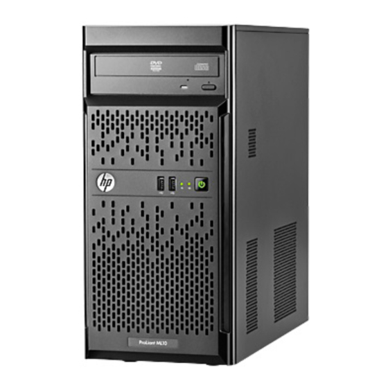
HP ProLiant ML10 Server
Maintenance and Service Guide
Abstract
This document is for an experienced service technician. It is helpful if you are qualified in the servicing of computer equipment and trained in
recognizing hazards in products with hazardous energy levels and are familiar with weight and stability precautions for rack installations.
Part Number: 730600-002
December 2013
Edition: 2
Advertisement
Table of Contents

Related Manuals for HP ProLiant ML10


Summary of Contents for HP ProLiant ML10
- Page 1 HP ProLiant ML10 Server Maintenance and Service Guide Abstract This document is for an experienced service technician. It is helpful if you are qualified in the servicing of computer equipment and trained in recognizing hazards in products with hazardous energy levels and are familiar with weight and stability precautions for rack installations.
- Page 2 © Copyright 2013 Hewlett-Packard Development Company, L.P. The information contained herein is subject to change without notice. The only warranties for HP products and services are set forth in the express warranty statements accompanying such products and services. Nothing herein should be construed as constituting an additional warranty. HP shall not be liable for technical or editorial errors or omissions contained herein.
-
Page 3: Table Of Contents
Processor ............................... 41 System board ............................44 System battery ............................52 Troubleshooting .......................... 54 Troubleshooting resources for previous HP ProLiant server models ..............54 Diagnostic tools .......................... 55 HP Insight Remote Support software ......................55 HP ROM-Based Setup Utility ........................55 USB support and functionality ........................ - Page 4 System board components ........................59 DIMM slot locations ........................60 System maintenance switch ......................61 NMI functionality ........................... 61 Fan locations ............................62 Cabling ............................. 63 Drive cabling ............................63 Front I/O assembly cabling ........................64 Optical drive cabling ..........................64 Ambient temperature sensor cabling ......................
-
Page 5: Customer Self Repair
HP specifies in the materials shipped with a replacement CSR part whether a defective part must be returned to HP. In cases where it is required to return the defective part to HP, you must ship the defective part back to HP within a defined period of time, normally five (5) business days. The defective part must be returned with the associated documentation in the provided shipping material. - Page 6 HP sono realizzati con numerosi componenti che possono essere riparati direttamente dal cliente (CSR, Customer Self Repair). Se in fase di diagnostica HP (o un centro di servizi o di assistenza HP) identifica il guasto come riparabile mediante un ricambio CSR, HP lo spedirà direttamente al cliente per la sostituzione.
- Page 7 La mancata restituzione del componente può comportare la fatturazione del ricambio da parte di HP. Nel caso di riparazione da parte del cliente, HP sostiene tutte le spese di spedizione e resa e sceglie il corriere/vettore da utilizzare.
- Page 8 Si, durante la fase de diagnóstico, HP (o los proveedores o socios de servicio de HP) identifica que una reparación puede llevarse a cabo mediante el uso de un componente CSR, HP le enviará dicho componente directamente para que realice su sustitución. Los componentes CSR se clasifican en dos categorías:...
- Page 9 HP podrá cobrarle por el de sustitución. En el caso de todas sustituciones que lleve a cabo el cliente, HP se hará cargo de todos los gastos de envío y devolución de componentes y escogerá la empresa de transporte que se utilice para dicho servicio.
- Page 10 Opcional – Peças cujo reparo feito pelo cliente é opcional. Essas peças também são projetadas para o reparo feito pelo cliente. No entanto, se desejar que a HP as substitua, pode haver ou não a cobrança de taxa adicional, dependendo do tipo de serviço de garantia destinado ao produto.
- Page 11 No caso desse serviço, a substituição de peças CSR é obrigatória. Se desejar que a HP substitua essas peças, serão cobradas as despesas de transporte e mão-de-obra do serviço. Customer self repair 11...
- Page 12 Customer self repair 12...
- Page 13 Customer self repair 13...
- Page 14 Customer self repair 14...
-
Page 15: Illustrated Parts Catalog
Optional—Parts for which customer self repair is optional. These parts are also designed for customer self repair. If, however, you require that HP replace them for you, there may or may not be additional charges, depending on the type of warranty service designated for your product. - Page 16 Optional: Opcional—Peças cujo reparo feito pelo cliente é opcional. Essas peças também são projetadas para o reparo feito pelo cliente. No entanto, se desejar que a HP as substitua, pode haver ou não a cobrança de taxa adicional, dependendo do tipo de serviço de garantia destinado ao produto.
-
Page 17: System Components
System components Illustrated parts catalog 17... - Page 18 Item Description Spare part Customer self number repair (on page 5) 300 W Integrated power supply 732598-001 Mandatory System fan 732595-001 Mandatory Heatsink and fan 732596-001 Mandatory Processor (includes alcohol pad and thermal — — compound) a) 3.10-GHz Intel Xeon E3-1220 v2 686686-001 Optional processor, 4 C, 8 MB, 69 W...
- Page 19 Optional—Parts for which customer self repair is optional. These parts are also designed for customer self repair. If, however, you require that HP replace them for you, there may or may not be additional charges, depending on the type of warranty service designated for your product.
- Page 20 Optional: Opcional—Peças cujo reparo feito pelo cliente é opcional. Essas peças também são projetadas para o reparo feito pelo cliente. No entanto, se desejar que a HP as substitua, pode haver ou não a cobrança de taxa adicional, dependendo do tipo de serviço de garantia destinado ao produto.
-
Page 21: Removal And Replacement Procedures
T-15 Torx screwdriver • Philips screwdriver (required for system fan removal) • HP Insight Diagnostics software Safety considerations Before performing service procedures, review all the safety information. Preventing electrostatic discharge To prevent damaging the system, be aware of the precautions you need to follow when setting up the system or handling parts. -
Page 22: Server Warnings And Cautions
This symbol on an RJ-45 receptacle indicates a network interface connection. WARNING: To reduce the risk of electric shock, fire, or damage to the equipment, do not plug telephone or telecommunications connectors into this receptacle. This symbol indicates the presence of a hot surface or hot component. If this surface is contacted, the potential for injury exists. -
Page 23: Power Down The Server
• Remove the front bezel (on page 24). Power down the server Before powering down the server for any upgrade or maintenance procedures, perform a backup of critical server data and programs. WARNING: To reduce the risk of personal injury, electric shock, or damage to the equipment, remove the power cord to remove power from the server. -
Page 24: Remove The Front Bezel
Place the server on its side. Unfasten the T-15 screw securing the access panel, and then slide the panel towards the rear of the server. Remove the front bezel The front bezel must be opened to access the drive cage and media bays. The bezel must remain closed during normal server operation. -
Page 25: Primary Non-Hot-Plug Lff Drive
Remove the front bezel. Primary non-hot-plug LFF drive CAUTION: To prevent improper cooling and thermal damage, do not operate the server unless all bays are populated with either a component or a blank. To remove the component: Back up all server data on the drive. Press the Power On/Standby button. - Page 26 Place the server on its side. Remove the access panel (on page 23). Disconnect the SATA and power cables from the drive: Press the cable lock under the connectors of both cables. Pull the cables out. If replacing the primary LFF drive180 mm SATA cable, disconnect it from the system board. Remove the drive: Unfasten and remove the four T-15 screws connected to the drive cage.
-
Page 27: Secondary Lff Drive And Drive Carrier
Slide out the drive to remove it. To replace the component, reverse the removal procedure. Secondary LFF drive and drive carrier To remove the component: Back up all data on the hard drive. Press the Power On/Standby button. The server powers down and enters standby mode. The system power LED changes from green to amber. - Page 28 Remove the access panel (on page 23). Remove the front bezel (on page 24). Disconnect the SATA and power cables from the drive: Press the cable lock under the connectors of both cables. Pull the cables out. Remove the two screws securing the LFF drive, and then remove it from the drive bay. Removal and replacement procedures 28...
-
Page 29: Front I/O Module
Loosen and remove the four screws securing the LFF drive, and then remove the drive from the drive carrier. To replace the component, reverse the removal procedure. Front I/O module To remove the component: Press the Power On/Standby button. The server powers down and enters standby mode. The system power LED changes from green to amber. -
Page 30: Ambient Temperature Sensor Cable
Remove the access panel (on page 23). Remove the front bezel (on page 24). Disconnect the front I/O cable connectors from the system board. Remove the front I/O module: Push the latch above the front I/O module. Slide the assembly to the left and remove the entire assembly out of the front I/O module chassis opening. - Page 31 The server powers down and enters standby mode. The system power LED changes from green to amber. Power is still applied to the server. Disconnect the power cord from the power source. Disconnect the power cord from the server. Place the server on its side. Remove the access panel (on page 23).
-
Page 32: System Fan
Remove the rubber stopper from the sensor cable. To replace the component, reverse the removal procedure. System fan To remove the component: Press the Power On/Standby button. The server powers down and enters standby mode. The system power LED changes from green to amber. -
Page 33: Integrated Power Supply
Disconnect the fan cable from the system board connector. Remove the screws securing the system fan, and then remove the fan. To replace the component, reverse the removal procedure. Integrated power supply To remove the component: Press the Power On/Standby button. The server powers down and enters standby mode. - Page 34 Place the server on its side. Remove the access panel (on page 23). Disconnect all power supply cables: Release the cable tie securing the power supply cables. Disconnect the cables from the system board connectors. Removal and replacement procedures 34...
-
Page 35: Expansion Slot Cover
Disconnect the power supply cables from all installed drives. Remove the power supply: Remove the four T-15 screws from the rear side of the power supply. Push and hold down the lever at the bottom of the power supply. Slide the power supply out, and then remove it. To replace the component, reverse the removal procedure. - Page 36 Disconnect the power cord from the power source. Disconnect the power cord from the server. Place the server on its side. Remove the access panel (on page 23). Remove the expansion slot cover retainer. Remove the expansion slot cover: If removing expansion slot cover from PCIe slots 1 or 3, push and remove the slot cover attached to the chassis.
-
Page 37: Expansion Board
The removal of these slot covers is permanent, and they cannot be replaced. If removing expansion slot cover from PCIe slots 2 or 4, pull up the slot cover and remove it from the chassis. To replace the component, reverse the removal procedure. Expansion board To remove the component: Press the Power On/Standby button. -
Page 38: Dimm
Place the server on its side. Remove the access panel (on page 23). Disconnect all cables connected to the expansion board. Remove the expansion slot cover ("Expansion slot cover" on page 35). Remove the expansion board. To replace the component, reverse the removal procedure. DIMM To remove the component: Press the Power On/Standby button. -
Page 39: Heatsink
Disconnect the power cord from the power source. Disconnect the power cord from the server. Place the server on its side. Remove the access panel (on page 23). Open the DIMM slot latches. Remove the DIMM. To replace the component, reverse the removal procedure. Heatsink To remove the component: Press the Power On/Standby button. - Page 40 The server powers down and enters standby mode. The system power LED changes from green to amber. Power is still applied to the server. Disconnect the power cord from the power source. Disconnect the power cord from the server. Place the server on its side. Remove the access panel (on page 23).
-
Page 41: Processor
Position the heatsink on the processor backplate Tighten the four corner screws completely to secure the heatsink in place. Connect the fan cable to the system board. Install the access panel. Return the server to an upright position. Connect the power cord to the server. Connect the power cord to the power source. - Page 42 Place the server on its side. Remove the access panel (on page 23). Remove the heatsink ("Heatsink" on page 39). CAUTION: To avoid damage to the processor, do not touch the bottom of the processor, especially the contact area. CAUTION: The pins on the processor socket are very fragile.
- Page 43 CAUTION: THE PINS ON THE SYSTEM BOARD ARE VERY FRAGILE AND EASILY DAMAGED. To avoid damage to the system board: Do not touch the processor socket contacts. • Do not tilt or slide the processor when lowering the processor into the socket. •...
-
Page 44: System Board
Apply all the grease to the top of the processor in the following pattern to ensure even distribution. Install the heatsink ("Heatsink" on page 39). Install the access panel. Return the server to an upright position. Connect the power cord to the server. Connect the power cord to the power source. - Page 45 Place the server on its side. Remove the access panel (on page 23). WARNING: To reduce the risk of personal injury from hot surfaces, allow the heatsink to cool before touching it. Remove the heatsink: Disconnect the fan cable from the system board. Loosen the four corner screws completely to disengage the heatsink.
- Page 46 Grasp the processor by the edges, and then lift it out of the socket. Remove all DIMMs ("DIMM" on page 38). If installed, remove the expansion board ("Expansion board" on page 37). Remove the failed system board: Loosen and remove all the system board screws. Slide the system board toward the front of the server.
- Page 47 Tilt and lift the system board up to remove it from the chassis. To replace the system board: Install the system board: Tilt down the system board and place it inside the chassis. Removal and replacement procedures 47...
- Page 48 Slide the system board in place, and then insert the screws to secure the board. CAUTION: Failure to completely open the processor locking lever prevents the processor from seating during installation, leading to hardware damage. CAUTION: To avoid damage to the processor, do not touch the bottom of the processor, especially the contact area.
- Page 49 Remove the processor socket cover. CAUTION: THE PINS ON THE SYSTEM BOARD ARE VERY FRAGILE AND EASILY DAMAGED. To avoid damage to the system board: Do not touch the processor socket contacts. • Do not tilt or slide the processor when lowering the processor into the socket. •...
- Page 50 Close the processor retaining bracket, and then secure the processor locking lever. Clean the old thermal grease from the heatsink and the top of the processor with the alcohol swab. Allow the alcohol to evaporate before continuing. Apply all the grease to the top of the processor in the following pattern to ensure even distribution. Install the heatsink: Position the heatsink on the processor backplate Tighten the four corner screws completely to secure the heatsink in place.
- Page 51 Connect the fan cable to the system board. CAUTION: When returning a damaged system board to HP, always install all processor socket covers to prevent damage to the processor sockets and system board. Install the processor socket cover on the failed system board.
-
Page 52: System Battery
System battery If the server no longer automatically displays the correct date and time, you might have to replace the battery that provides power to the real-time clock. WARNING: The computer contains an internal lithium manganese dioxide, a vanadium pentoxide, or an alkaline battery pack. A risk of fire and burns exists if the battery pack is not properly handled. - Page 53 Remove the battery. To replace the component, reverse the removal procedure. For more information about battery replacement or proper disposal, contact an authorized reseller or an authorized service provider. Removal and replacement procedures 53...
-
Page 54: Troubleshooting
HP ProLiant servers and server blade models prior to Gen8. This guide includes problem-specific flowcharts to help you navigate complex troubleshooting processes. To view the guide, select a language: •... -
Page 55: Diagnostic Tools
HP strongly recommends that you install HP Insight Remote Support software to complete the installation or upgrade of your product and to enable enhanced delivery of your HP Warranty, HP Care Pack Service, or HP contractual support agreement. HP Insight Remote Support supplements your monitoring 24 x 7 to ensure maximum system availability by providing intelligent event diagnosis, and automatic, secure submission of hardware event notifications to HP, which will initiate a fast and accurate resolution, based on your product’s... -
Page 56: Usb Support And Functionality
ASR is a feature that causes the system to restart when a catastrophic operating system error occurs, such as a blue screen, ABEND (does not apply to HP ProLiant DL980 Servers), or panic. A system fail-safe timer, the ASR timer, starts when the System Management driver, also known as the Health Driver, is loaded. When the operating system is functioning properly, the system periodically resets the timer. -
Page 57: Component Identification
Component identification Front panel components Item Description Drive bay USB connectors Front panel LEDs and buttons Component identification 57... -
Page 58: Rear Panel Components
Item Description Status NIC link/activity LED Green = Network link Flashing green = Network link and activity Off = No link to network (If the power is off, view the rear panel NIC LEDs for status.) System health LED Green = Normal Amber = System degraded Red = System critical System power button/LED... -
Page 59: Rear Panel Leds And Buttons
Rear panel LEDs and buttons Item Description Status NIC status LED Solid green = Link to network Flashing green (1 Hz/cycle per sec) = Network active Off = No network activity NIC link LED Solid green = Link exists Off = No link exists Power supply LED Solid green = System on/System in standby Off = No power present... -
Page 60: Dimm Slot Locations
Item Description Processor socket DIMM slots (4) 24-pin power supply connector System fan connector Internal USB connector System battery SATA connectors (2) Ambient temperature sensor connector Mini-SAS connector Front I/O connector Processor fan connector Front USB connector Slot 1 PCIe2x16 (16, 8, 4, 1)* Slot 2 PCIe2x8 (4, 1) Slot 3 PCIe2x8 (4, 1) Slot 4 PCIe2x4 (1) -
Page 61: System Maintenance Switch
To force the system to invoke the NMI handler and generate a crash dump log, do one of the following: • Use the iLO Virtual NMI feature. • Short the NMI header ("System board components" on page 59). For more information, see the HP website (http://www.hp.com/support/NMI). Component identification 61... -
Page 62: Fan Locations
Fan locations Item Description Rear system fan Processor-heatsink fan assembly Component identification 62... -
Page 63: Cabling
Cabling Drive cabling • Primary non-hot-plug LFF drive cabling Item Description SATA cable Power (P3) cable • Secondary non-hot-plug LFF drive cabling Cabling 63... -
Page 64: Front I/O Assembly Cabling
Item Description SATA cable Power (P6) cable Front I/O assembly cabling Optical drive cabling Item Description SATA cable Power (P6) cable Cabling 64... -
Page 65: Ambient Temperature Sensor Cabling
Ambient temperature sensor cabling Fan cabling • System fan Cabling 65... -
Page 66: Power Supply Cabling
• Processor fan Power supply cabling Item Description 4-pin power supply cable 24-pin power supply cable Cabling 66... -
Page 67: Specifications
16.5 cm (6.5 in) Width 5.94 kg (13.08 lb) Weight Power supply specifications The server supports one HP 300 W Integrated Power Supply. CAUTION: Check the system and power supply input ratings before powering up the server. Specification Value Input requirements... - Page 68 No less than 82% at 100% load Efficiency No less than 85% at 50% load No less than 82% at 20% load Power supply output 300 W Rated output power Specifications 68...
-
Page 69: Acronyms And Abbreviations
Acronyms and abbreviations ABEND abnormal end Advanced Memory Protection Automatic Server Recovery Customer Self Repair Integrated Lights-Out large form factor nonmaskable interrupt NVRAM nonvolatile memory PCIe Peripheral Component Interconnect Express POST Power-On Self Test RBSU ROM-Based Setup Utility SATA serial ATA Acronyms and abbreviations 69... - Page 70 small form factor Systems Insight Manager universal serial bus Acronyms and abbreviations 70...
-
Page 71: Documentation Feedback
Documentation feedback HP is committed to providing documentation that meets your needs. To help us improve the documentation, send any errors, suggestions, or comments to Documentation Feedback (mailto:docsfeedback@hp.com). Include the document title and part number, version number, or the URL when submitting your feedback. -
Page 72: Index
I/O 64 health driver 56 cabling, optical drive 64 heatsink 39 cautions 22 HP Insight Remote Support software 55 components 15, 57 HP technical support 5 components, front panel 57 components, identification 15, 57 components, rear panel 58... - Page 73 memory dump 61 technical support 5 troubleshooting 54 NMI functionality 59, 61 troubleshooting resources 54 NMI header 61 USB support 56 operating system crash 56, 61 utilities 55 optical drive cabling 64 utilities, deployment 55 part numbers 15 warnings 22 power supply cabling 66 weight 67 powering down 23...