Hitachi UR 18DSL2 Service Manual
Cordless radio
Hide thumbs
Also See for UR 18DSL2:
- Handling instructions manual (17 pages) ,
- Handling instructions manual (41 pages) ,
- Handling instructions manual (93 pages)
Advertisement
Quick Links
PRODUCT NAME
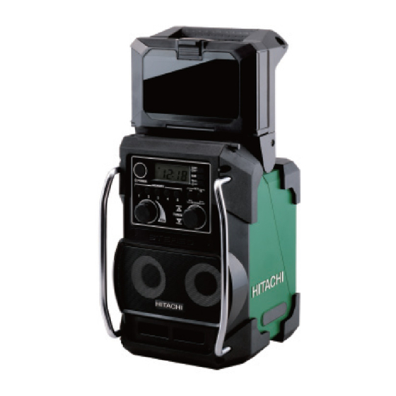
Hitachi Cordless Radio
UR 18DSL2
Model
CONTENTS
TROUBLESHOOTING GUIDE ---------------------------------------------------------------------------------------------- 1
REPAIR GUIDE ---------------------------------------------------------------------------------------------------------------- 4
STANDARD REPAIR TIME (UNIT) SCHEDULES --------------------------------------------------------------------10
LIST No.
UR 18DSL2: J862
Sep. 2013
Page
International Sales Division
U
Advertisement

Related Manuals for Hitachi UR 18DSL2


Summary of Contents for Hitachi UR 18DSL2
- Page 1 LIST No. UR 18DSL2: J862 Sep. 2013 PRODUCT NAME Hitachi Cordless Radio UR 18DSL2 Model Page CONTENTS TROUBLESHOOTING GUIDE ---------------------------------------------------------------------------------------------- 1 REPAIR GUIDE ---------------------------------------------------------------------------------------------------------------- 4 STANDARD REPAIR TIME (UNIT) SCHEDULES --------------------------------------------------------------------10 International Sales Division...
- Page 2 Power can be turned on by Battery is abnormal or depleted. Charge the battery or replace it with a normal battery. (1) Power Model UR 18DSL2, and check whether both methods (i) and (ii). cannot AC-Adapter [501] is abnormal. Replace AC-Adapter [501] with a new one.
- Page 3 Trouble Check method Check result Cause Corrective action (i) Put the Model UR 18DSL2 in a place The broadcast can be Radio waves are blocked by surrounding Move the Model UR 18DSL2 to a better reception (3) AM radio without surrounding walls or buildings received.
- Page 4 Sound is not produced. Go to the next check. Go to check method (6)-(ii). (ii) Disassemble the Model UR 18DSL2, Some connectors are Same as on the left. Connect the disconnected connectors. and then check whether all connectors disconnected.
-
Page 5: Repair Guide
REPAIR GUIDE [Bold] numbers in the descriptions below correspond to item numbers in the parts list for the Model UR 18DSL2. The rechargeable battery must be removed from the Model UR 18DSL2 before disassembling or repairing the Model UR 18DSL2. - Page 6 2. Disassembly and reassembly of the back housing <<Disassembly>> (1) Remove the five Machine Screws (W/Flange) M3 x 10 (Black) [9]. Then you can remove the Speaker Back Cover [23]. (Fig. 2) Fig. 2 • Inside the back housing Remove the five Machine Screws (W/Flange) M3 x 10 (Black) [9] fixing the Speaker Back Cover [23].
-
Page 7: Rubber Antenna
<<Reassembly>> Reverse the disassembly procedure. Note the following at reassembly: (1) When reassembling Terminal Ass'y (E) [34], be sure to mount the jack located internally on the left side prior to the EB battery box. (The two parts cannot be assembled if mounted in reverse order.) (2) Be careful to prevent internal wires from being caught between other parts. -
Page 8: Machine Screw M4 X 15 (Black)
(2) Remove the five Machine Screws (W/Flange) M2.6 x 10 (Black) [19]. Then you can remove the Controller PCBA [17]. (Fig. 6) Fig. 6 • Controller PCBA [17] at the top of the front housing Five Machine Screws (W/Flange) M2.6 x 10 (Black) [19] <<Reassembly>>... - Page 9 Antenna [1] by 90 degrees as shown in the figure below, and then use a screwdriver to remove the screw fixing the joint from the right side of the Model UR 18DSL2 (having a shaft at least 140 mm long). (Fig. 10) (3) Replace the receiver of the Rubber Antenna [1] with a new one, and then tighten the screw fixing the joint.
- Page 10 • While receiving a FM radio broadcast, tap the side of the Model UR 18DSL2 with your hand, and then check that noise does not increase or sound is not interrupted each time you tap the radio. (If noise...
-
Page 11: Dial
STANDARD REPAIR TIME (UNIT) SCHEDULES Variable MODEL 60 min. Fixed Work Flow UR 18DSL2 Function PCBA Front Housing Controller Ass’y PCBA Dial Cover (A) Cover (B) Speaker Cover General Assembly Speaker Back Housing Back Cover Terminal (D) Cover (D) AA Battery Box... - Page 12 LIST NO. J862 CORDLESS RADIO 2013· 9 · 27 Model UR 18DSL2 (E1)
- Page 13 UR 18DSL2 - 2 - 9 - 13...
- Page 14 PARTS UR 18DSL2 ITEM CODE NO. DESCRIPTION REMARKS USED 335-813 RUBBER ANTENNA 331-605 GUARD BAR 331-606 MACHINE SCREW M4 X 15 (BLACK) 331-607 TPE COVER (A) 336-291 SPEAKER COVER 331-609 DIAL 334-597 FUNCTION LABEL 334-598 FRONT HOUSING ASS'Y INCLUD. 7...
-
Page 15: Alternative Parts
PARTS UR 18DSL2 ITEM CODE NO. DESCRIPTION REMARKS USED 335-809 HANDLE BOX 336-304 PHONE BELT 336-305 METAL SHAFT (D) 335-806 HANDLE (L) 336-306 HANDLE 335-807 HANDLE (R) 336-308 HANDLE ARM COVER 336-307 HANDLE BRACKET SPRING (BLACK) 331-641 HANDLE BRACKET 331-656...