Table of Contents
Advertisement
Advertisement
Table of Contents

Related Manuals for Asus H81M-CT


Summary of Contents for Asus H81M-CT
- Page 1 H81M-CT...
- Page 2 Product warranty or service will not be extended if: (1) the product is repaired, modified or altered, unless such repair, modification of alteration is authorized in writing by ASUS; or (2) the serial number of the product is defaced or missing.
-
Page 3: Table Of Contents
Contents Safety information ..................iv About this guide ..................iv Package contents ..................vi H81M-CT specifications summary ............vi Chapter 1: Product introduction Before you proceed ..............1-1 Motherboard overview ..............1-1 Central Processing Unit (CPU) ........... 1-3 System memory ................1-7 Expansion slots ................ -
Page 4: Safety Information
Safety information Electrical safety • To prevent electrical shock hazard, disconnect the power cable from the electrical outlet before relocating the system. • When adding or removing devices to or from the system, ensure that the power cables for the devices are unplugged before the signal cables are connected. If possible, disconnect all power cables from the existing system before you add a device. -
Page 5: Conventions Used In This Guide
Refer to the following sources for additional information and for product and software updates. ASUS websites The ASUS website provides updated information on ASUS hardware and software products. Refer to the ASUS contact information. Optional documentation Your product package may include optional documentation, such as warranty flyers, that may have been added by your dealer. -
Page 6: Package Contents
* Hyper DIMM support is subject to the physical characteristics of individual CPUs. Please refer to the Memory QVL (Qualified Vendors List) for details. ** Refer to www.asus.com for the latest Memory QVL (Qualified Vendors List). ® *** Due to Intel chipset limitation, the DDR3 1600MHz and higher memory modules on XMP mode will run at the maximum transfer rate of DDR3 1600MHz. - Page 7 H81M-CT specifications summary Intel H81 Express Chipset ® - 2 x USB 3.0 ports at back panel (2 ports at midboard) - 8 x USB 2.0 ports (4 ports at midboard, 4 ports at the back panel) 1 x PS/2 keyboard port (purple)
- Page 8 viii...
-
Page 9: Chapter 1: Product Introduction
Placement direction When installing the motherboard, place it into the chassis in the correct orientation. The edge with external ports goes to the rear part of the chassis as indicated in the image. 1.2.2 Screw holes Place six screws into the holes indicated by circles to secure the motherboard to the chassis. Do not overtighten the screws! Doing so can damage the motherboard. ASUS H81M-CT... -
Page 10: Motherboard Layout
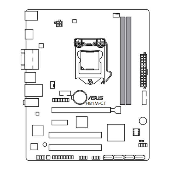
Place this side towards the rear of the chassis H81M-CT 1.2.3 Motherboard layout 19.8cm(7.8in) KBMS CPU_FAN DIGI +VRM ATX12V HDMI 1442K LGA1150 USB56 CHA_FAN COM2 LAN_USB34 BATTERY AUDIO H81M-CT USB3_12 PCIEX16 8111G BUZZER PCIEX1_1 1083 Super Intel ® BIOS PCI1... -
Page 11: Central Processing Unit (Cpu)
8. System panel connector (10-1 pin F_PANEL) 9. Intel H81 Serial ATA 3.0Gb/s connector (7-pin SATA3G_1~2) ® 10. Intel H81 Serial ATA 6.0Gb/s connector (7-pin SATA6G_1~2) ® 11. USB 2.0 connectors (10-1 pin USB910, USB1112) 12. LPT connector (26-1 pin LPT) 13. Mono out header (2-pin MONO_OUT) 14. Front panel audio connector (10-1 pin AAFP) 15. Onboard LED (SB_PWR) 16. TPM header (20-1 pin TPM) Central Processing Unit (CPU) This motherboard comes with a surface mount LGA1150 socket designed for the Intel 4th ® generation Core™ i7 / Core™ i5 / Core™ i3, Pentium , Celeron processors. ® ® H81M-CT H81M-CT CPU socket LGA1150 ASUS H81M-CT... -
Page 12: Installing The Cpu
Unplug all power cables before installing the CPU. • Ensure that you install the correct CPU designed for the LGA1150 socket only. DO NOT install a CPU designed for LGA1155 and LGA1156 sockets on the LGA1150 socket. • Upon purchase of the motherboard, ensure that the PnP cap is on the socket and the socket contacts are not bent. Contact your retailer immediately if the PnP cap is missing, or if you see any damage to the PnP cap/socket contacts/motherboard components. ASUS will shoulder the cost of repair only if the damage is shipment/ transit-related. • Keep the cap after installing the motherboard. ASUS will process Return Merchandise Authorization (RMA) requests only if the motherboard comes with the cap on the LGA1150 socket. • The product warranty does not cover damage to the socket contacts resulting from incorrect CPU installation/removal, or misplacement/loss/incorrect removal of the PnP cap. 1.3.1 Installing the CPU Chapter 1: Product introduction... -
Page 13: Cpu Heatsink And Fan Assembly Installation
1.3.2 CPU heatsink and fan assembly installation Apply the Thermal Interface Material to the CPU heatsink and CPU before you install the heatsink and fan if necessary. ASUS H81M-CT... - Page 14 To install the CPU heatsink and fan assembly To uninstall the CPU heatsink and fan assembly Chapter 1: Product introduction...
-
Page 15: System Memory
System memory 1.4.1 Overview This motherboard comes with two Double Data Rate 3 (DDR3) Dual Inline Memory Module (DIMM) sockets. A DDR3 module is notched differently from a DDR or DDR2 module. DO NOT install a DDR or DDR2 memory module to the DDR3 slot. According to Intel CPU spec, DIMM voltage below 1.65V is recommended to protect the ® CPU. Channel Sockets Channel A DIMM_A1 Channel B DIMM_B1 H81M-CT H81M-CT 240-pin DDR3 DIMM sockets 1.4.2 Memory configurations You may install 1GB, 2GB, 4GB, and 8GB unbuffered non-ECC DDR3 DIMMs into the DIMM sockets. • You may install varying memory sizes in Channel A and Channel B. The system maps the total size of the lower-sized channel for the dual-channel configuration. Any excess memory from the higher-sized channel is then mapped for single-channel operation. • Due to Intel chipset limitation, DDR3 1600MHz and higher memory modules on XMP ® mode will run at the maximum transfer rate of DDR3 1600MHz. • Always install DIMMs with the same CAS latency. For optimal compatibility, we recommend that you install memory modules of the same version or date code (D/C) from the same vendor. Check with the retailer to get the correct memory modules. -
Page 16: Installing A Dimm
• The default memory operation frequency is dependent on its Serial Presence Detect (SPD), which is the standard way of accessing information from a memory module. Under the default state, some memory modules for overclocking may operate at a lower frequency than the vendor-marked value. To operate at the vendor-marked or at a higher frequency, refer to section 2.5 Ai Tweaker menu for manual memory frequency adjustment. • For system stability, use a more efficient memory cooling system to support a full memory load (2 DIMMs) or overclocking condition. • Visit the ASUS website at: www.asus.com for the latest QVL. 1.4.3 Installing a DIMM Unplug the power supply before adding or removing DIMMs or other system components. Failure to do so can cause severe damage to both the motherboard and the components. Press the retaining clips DIMM notch outward to unlock a DIMM socket. Align a DIMM on the socket such that the notch on the DIMM matches the DIMM slot key on the socket. -
Page 17: Expansion Slots
Installing an expansion card To install an expansion card: Before installing the expansion card, read the documentation that came with it and make the necessary hardware settings for the card. Remove the system unit cover (if your motherboard is already installed in a chassis). Remove the bracket opposite the slot that you intend to use. Keep the screw for later use. Align the card connector with the slot and press firmly until the card is completely seated on the slot. Secure the card to the chassis with the screw you removed earlier. Replace the system cover. 1.5.2 Configuring an expansion card After installing the expansion card, configure it by adjusting the software settings. Turn on the system and change the necessary BIOS settings, if any. See Chapter 2 for information on BIOS setup. Assign an IRQ to the card. Install the software drivers for the expansion card. When using PCI cards on shared slots, ensure that the drivers support “Share IRQ” or that the cards do not need IRQ assignments. Otherwise, conflicts will arise between the two PCI groups, making the system unstable and the card inoperable. ASUS H81M-CT... -
Page 18: Pci Express X16 Slot
1.5.3 PCI Express 2.0 x1 slots This motherboard supports PCI Express x1 network cards, SCSI cards, and other cards that comply with the PCI Express specifications. 1.5.4 PCI Express x16 slot This motherboard has a PCI Express x16 slot that supports PCI Express x16 graphic cards complying with the PCI Express specifications. 1.5.3 PCI slots The PCI slot supports cards such as a LAN card, SCSI card, USB card, and other cards that comply with PCI specifications. IRQ assignments for this motherboard PCIEx16_1 shared – – – – – – – PCIEx1_1 shared – – – – –... -
Page 19: Jumpers
Jumpers Clear RTC RAM (3-pin CLRTC) This jumper allows you to clear the Real Time Clock (RTC) RAM in CMOS. You can clear the CMOS memory of date, time, and system setup parameters by erasing the CMOS RTC RAM data. The onboard button cell battery powers the RAM data in CMOS, which include system setup information such as system passwords. CLRTC H81M-CT Normal Clear RTC (Default) H81M-CT Clear RTC RAM To erase the RTC RAM: Turn OFF the computer and unplug the power cord. Move the jumper cap from pins 1-2 (default) to pins 2-3. Keep the cap on pins 2-3 for about 5-10 seconds, then move the cap back to pins 1-2. 3. Plug the power cord and turn ON the computer. Hold down the <Del> key during the boot process and enter BIOS setup to re- enter data. Except when clearing the RTC RAM, never remove the cap on CLRTC jumper default position. Removing the cap will cause system boot failure! • If the steps above do not help, remove the onboard battery and move the jumper again to clear the CMOS RTC RAM data. After clearing the CMOS, reinstall the battery. •... -
Page 20: Connectors
Connectors 1.7.1 Rear panel connectors PS/2 mouse port (green). This port is for a PS/2 mouse. Video Graphics Adapter (VGA) port. This 15-pin port is for a VGA monitor or other VGA-compatible devices. LAN (RJ-45) port. This port allows Gigabit connection to a Local Area Network (LAN) through a network hub. LAN port LED indications Activity/Link LED Speed LED Speed Activity Link Status Description Status Description No link 10Mbps connection Orange Linked ORANGE 1Gbps connection Orange... -
Page 21: Internal Connectors
Use a chassis with HD audio module in the front panel to support an 7.1-channel audio output. USB 2.0 ports. These 4-pin Universal Serial Bus (USB) ports are for USB 2.0/1.1 devices. Serial (COM) port. This 9-pin communication port is for pointing devices or other serial devices. HDMI port. This port is for a High-Definition Multimedia Interface (HDMI) connector, and is HDCP compliant allowing playback of HD DVD, Blu-ray, and other protected content. PS/2 keyboard port (purple). This port is for a PS/2 keyboard. 1.7.2 Internal connectors TPM connector (20-1 pin TPM) This connector supports a Trusted Platform Module (TPM) system, which securely store keys, digital certificates, passwords and data. A TPM system also helps enhance network security, protect digital identities, and ensures platform integrity. PIN 1 H81M-CT H81M-CT TPM connector The TPM module is purchased separately. ASUS H81M-CT 1-13... -
Page 22: Atx Power Connectors
Power OK -5 Volts PIN 1 +5 Volts +5 Volts PSON# H81M-CT -12 Volts +3 Volts +3 Volts +3 Volts PIN 1 H81M-CT ATX power connectors • For a fully configured system, we recommend that you use a power supply unit (PSU) that complies with ATX 12V Specification 2.0 (or later version) and provides a minimum power of 350W. • DO NOT forget to connect the 4-pin ATX +12V power plug. Otherwise, the system will not boot up. • We recommend that you use a PSU with higher power output when configuring a system with more power-consuming devices or when you intend to install additional devices. The system may become unstable or may not boot up if the power is inadequate. -
Page 23: Intelh81 Serial Ata 6.0Gb/S Connector
This connector is for a chassis-mounted front panel audio I/O module that supports either HD Audio or legacy AC`97 audio standard. Connect one end of the front panel audio I/O module cable to this connector. AAFP PIN 1 PIN 1 H81M-CT HD-audio-compliant Legacy AC’97 pin definition compliant definition H81M-CT Front panel audio connector • We recommend that you connect a high-definition front panel audio module to this connector to avail of the motherboard’s high-definition audio capability. • If you want to connect a high-definition front panel audio module to this connector, set the Front Panel Type item in the BIOS setup to [HD]. If you want to connect an AC’97 front panel audio module to this connector, set the item to [AC97]. By default, this connector is set to [HD]. See section 2.6.7 Onboard Devices Configuration for details. Intel H81 Serial ATA 6.0Gb/s connector s(7-pin SATA6G_1~2) ®... - Page 24 H81 Serial ATA 3.0Gb/s connectors (7-pin SATA3G_1~2) ® These connectors connect to Serial ATA 3.0 Gb/s hard disk drives via Serial ATA 3.0 Gb/s signal cables. SATA3G_1 SATA3G_2 H81M-CT H81M-CT SATA 3.0Gb/s connectors • You must install Windows. XP Service Pack 3 or later version before using Serial ATA hard disk drives. • When using hot-plug and NCQ, set the SATA Mode Selection item in the BIOS to [AHCI] CPU and chassis fan connectors (4-pin CPU_FAN, 4-pin CHA_FAN) Connect the fan cables to the fan connectors on the motherboard, ensuring that the black wire of each cable matches the ground pin of the connector.
-
Page 25: Usb 3.0/Usb 2.0 Connector
The USB 2.0 module is purchased separately. USB 3.0 connector (20-1 pin USB3_12) This connector allows you to connect a USB 3.0 module for additional USB 3.0 front or rear panel ports. With an installed USB 3.0 module, you can enjoy all the benefits of USB 3.0 including faster data transfer speeds of up to 5Gbps, faster charging time for USB-chargeable devices, optimized power efficiency, and backward compatibility with USB 2.0. USB3_12 PIN 1 USB3+5V USB3+5V IntA_P1_SSRX- IntA_P2_SSRX- IntA_P1_SSRX+ IntA_P2_SSRX+ IntA_P1_SSTX- IntA_P2_SSTX- IntA_P1_SSTX+ H81M-CT IntA_P2_SSTX+ IntA_P1_D- IntA_P2_D- IntA_P1_D+ IntA_P2_D+ H81M-CT USB3.0 Front panel connector The USB 3.0 module is purchased separately. ASUS H81M-CT 1-17... - Page 26 Serial port connector (10-1 pin COM) This connector is for a serial (COM) port. Connect the serial port module cable to this connector, then install the module to a slot opening at the back of the system chassis. H81M-CT H81M-CT Serial port connectors The COM module is purchased separately. Mono out header (2-pin MONO_OUT) This internal mono out header allows connection to an internal, low power speaker for basic system sound capability. The subsystem is capable of driving a speaker load of 4 Ohms at 2 Watts (rms). MONO_OUT PIN 1 H81M-CT H81M-CT MONO_OUT connector 1-18 Chapter 1: Product introduction...
-
Page 27: Onboard Leds
System panel connector (10-1 pin PANEL) This connector supports several chassis-mounted functions. F_PANEL +PWR LED PWR BTN PIN 1 H81M-CT +HDD_LED RESET H81M-CT System panel connector • System power LED (2-pin PWR_LED) This 2-pin connector is for the system power LED. Connect the chassis power LED cable to this connector. The system power LED lights up when you turn on the system power, and blinks when the system is in sleep mode. • Hard disk drive activity LED (2-pin HDD_LED) This 2-pin connector is for the HDD Activity LED. Connect the HDD Activity LED cable to this connector. The HDD LED lights up or flashes when data is read from or written to the HDD. • ATX power button/soft-off button (2-pin PWR_BTN) This connector is for the system power button. -
Page 28: Software Support
Systems (OS). Always install the latest OS version and corresponding updates to maximize the features of your hardware. Motherboard settings and hardware options vary. Refer to your OS documentation for detailed information. 1.9.2 Support DVD information The Support DVD that comes with the motherboard package contains the drivers, software applications, and utilities that you can install to avail all motherboard features. The contents of the Support DVD are subject to change at any time without notice. Visit the ASUS website at www.asus.com for updates. To run the Support DVD Place the Support DVD into the optical drive. If Autorun is enabled in your computer, the DVD automatically displays the Specials screen which lists the unique features of your ASUS motherboard. Click Drivers, Utilities, AHCI Driver, Manual, Contact and Specials tabs to display their respective menus. The following screen is for reference only. Click an icon to display Support DVD/motherboard... -
Page 29: Chapter 2: Bios Information
Managing and updating your BIOS Save a copy of the original motherboard BIOS file to a USB flash disk in case you need to restore the BIOS in the future. Copy the original motherboard BIOS using the ASUS Update utility. -
Page 30: Asus Ez Flash 2
2.1.2 ASUS EZ Flash 2 The ASUS EZ Flash 2 feature allows you to update the BIOS without using an OS‑based utility. Before you start using this utility, download the latest BIOS file from the ASUS website at www.asus.com. To update the BIOS using EZ Flash 2: Insert the USB flash disk that contains the latest BIOS file to the USB port. -
Page 31: Asus Crashfree Bios 3 Utility
2.1.3 ASUS CrashFree BIOS 3 utility The ASUS CrashFree BIOS 3 is an auto recovery tool that allows you to restore the BIOS file when it fails or gets corrupted during the updating process. You can restore a corrupted BIOS file using the motherboard support DVD or a USB flash drive that contains the updated BIOS file. - Page 32 Insert the DOS‑bootable USB flash drive with the latest BIOS file and BIOS Updater to your computer’s USB port. Boot your computer. When the ASUS Logo appears, press <F8> to show the BIOS Boot Device Select Menu. Select the optical drive as the boot device. The DOS screen appears.
- Page 33 Ensure to load the BIOS default settings to ensure system compatibility and stability. Select the Load Optimized Defaults item under the Exit menu. Refer to section 2.10 Exit menu for details. • Ensure to connect all SATA hard disk drives after updating the BIOS file if you have disconnected them. ASUS H81M-CT...
-
Page 34: Bios Setup Program
The BIOS setup screens shown in this section are for reference purposes only, and may not exactly match what you see on your screen. • Visit the ASUS website at www.asus.com to download the latest BIOS file for this motherboard. •... -
Page 35: Advanced Mode
The highlighted item on the menu bar displays the specific items for that menu. For example, selecting Main shows the Main menu items. The other items (Ai Tweaker, Advanced, Monitor, Boot, Tool, and Exit) on the menu bar have their respective menu items. ASUS H81M-CT... -
Page 36: Submenu Items
Back button This button appears when entering a submenu. Press <Esc> or use the USB mouse to click this button to return to the previous menu screen. Submenu items A greater than sign (>) before each item on any menu screen means that the item has a submenu. -
Page 37: My Favorites
Favorites page. You cannot add the following items to My Favorites: • Items with submenu options • User‑configurable items such as language and boot device order • Configuration items such as Memory SPD Information, system time and date ASUS H81M-CT... -
Page 38: Main Menu
Main menu The Main menu screen appears when you enter the Advanced Mode of the BIOS Setup program. The Main menu provides you an overview of the basic system information, and allows you to set the system date, time, language, and security settings. 2.4.1 System Language [English] Allows you to choose the BIOS language version from the options. -
Page 39: Administrator Password
To clear the user password, follow the same steps as in changing a user password, but press <Enter> when prompted to create/confirm the password. After you clear the password, the User Password item on top of the screen shows Not Installed. ASUS H81M-CT 2-11... -
Page 40: Ai Tweaker Menu
Ai Tweaker menu The Ai Tweaker menu items allow you to configure overclocking‑related items. Be cautious when changing the settings of the Ai Tweaker menu items. Incorrect field values can cause the system to malfunction. The configuration options for this section vary depending on the CPU and DIMM model you installed on the motherboard. -
Page 41: Advanced Menu
Allows legacy operating systems to boot even without support for CPUs with extended CPUID functions. [Disabled] Disables this function. Execute Disable Bit [Enabled] [Enabled] Enables the No‑Execution Page Protection Technology. [Disabled] Forces the XD feature flag to always return to zero (0). ASUS H81M-CT 2‑13... - Page 42 Intel Virtualization Technology [Disabled] [Enabled] Allows a hardware platform to run multiple operating systems separately and simultaneously, enabling one system to virtually function as several systems. [Disabled] Disables this function. Hardware Prefetcher [Enabled] [Enabled] Allows a hardware platform to automatically analyze the requirements and prefetch data and codes for the CPU.
-
Page 43: Pch Configuration
The following items appear only when you set the Intel Rapid Start Technology to [Enabled]. Entry on S3 RTC Wake [Enabled] The system automatically wakes up and set to Rapid Start Technology S4 mode. Configuration options: [Enabled] [Disabled] ASUS H81M-CT 2-15... -
Page 44: Sata Configuration
Entry After [x] Allows you to set the wake‑up time.The values range from 0 (immediately) to 120. Active Page Threshold Support [Enabled] The system automatically set itself to sleep when the partition size is not enough for Rapid Start Technology to work. Configuration options: [Enabled] [Disabled] Active Memory Threshold [0] Key in the value for the additional partition size for Rapid Start Technology to work. -
Page 45: System Agent Configuration
The iGPU shared system memory size will be fixed at 64MB. Configuration options: [Disabled] [Enabled] DMI Configuration Allows you to control various DMI functions. DMI Gen 2 [Auto] Allows you to enable or disable DMI Gen 2. Configuration options: [Auto] [Enabled] [Disabled] ASUS H81M-CT 2-17... -
Page 46: Nb Pcie Configuration
NB PCIe Configuration Allows you to configure the NB PCI Express settings. PCIEX16_1 Link Speed [Auto] Allows you to configure the PCIEX16_1 speed. Configuration options: [Auto] [Gen1] [Gen2] DMI Link ASPM Control [Auto] Allows you to enable or disable the control of Active State Power Management on SA side of the DMI Link. -
Page 47: Platform Misc Configuration
Sets the front panel audio connector (AAFP) mode to high definition audio. [AC97] Sets the front panel audio connector (AAFP) mode to legacy AC’97 Realtek LAN Controller [Enabled] [Enabled] Enables the Realtek LAN controller. [Disabled] Disables the controller. ASUS H81M-CT 2-19... -
Page 48: Parallel Port Configuration
Realtek PXE Option Rom [Disabled] This item appears only when you set the previous item to [Enabled] and allows you to enable or disable the PXE OptionRom of the Realtek LAN controller. Configuration options: [Enabled] [Disabled] Serial Port / Serial Port 1 Configuration The sub‑items in this menu allow you to set the serial port configuration. -
Page 49: Network Stack Configuration
This item allows user to disable or enable the Ipv4 PXE Boot support. Configuration options: [Disabled] [Enabled] Ipv6 PXE Support [Enabled] This item allows user to disable or enable the Ipv6 PXE Boot support. Configuration options: [Disabled] [Enabled] ASUS H81M-CT 2-21... -
Page 50: Monitor Menu
Monitor menu The Monitor menu displays the system temperature/power status, and allows you to change the fan settings. Scroll down to display the other items. 2.7.1 CPU / System Temperature Status The onboard hardware monitor automatically detects and displays the CPU/system temperature status. -
Page 51: Boot Menu
Post Report [5 sec] This item appears only when you set Quiet Boot to [Disabled]. This item allows you to select a desired post report waiting time. Configuration options: [1 sec] ~ [10 sec] [Until Press ESC]. ASUS H81M-CT 2‑23... -
Page 52: Secure Boot
2.8.2 Bootup NumLock State [On] [On] Sets the power‑on state of the NumLock to [On]. [Off] Sets the power‑on state of the NumLock to [Off]. 2.8.3 Wait for ‘F1’ If Error [Enabled] When this item is set to [Enabled], the system waits for the F1 key to be pressed when error occurs. -
Page 53: Key Management
The PK file must be formatted as a UEFI variable structure with time‑based authenticated variable. KEK Management The KEK (Key‑exchange Key or Key Enrollment Key) manages the Signature database (db) and Revoked Signature database (dbx). Key‑exchange Key (KEK) refers to Microsoft Secure Boot Key‑Enrollment Key (KEK). ® ASUS H81M-CT 2-25... - Page 54 Load KEK from File Allows you to load the downloaded KEK from a USB storage device. Append KEK from file Allows you to load the additional KEK from a storage device for an additional db and dbx loaded management. The KEK file must be formatted as a UEFI variable structure with time‑based authenticated variable.
-
Page 55: Tools Menu
<Enter> to display the submenu. 2.9.1 ASUS EZ Flash 2 Utility Allows you to run ASUS EZ Flash 2. Press [Enter] to launch the ASUS EZ Flash 2 screen. For more details, see section 2.1.2 ASUS EZ Flash 2. ASUS H81M-CT... -
Page 56: Asus Spd Information
2.9.2 ASUS O.C. Profile This item allows you to store or load multiple BIOS settings. The Setup Profile Status items show Not Installed if no profile is created. Label Allows you to input the label of the setup profile. Save to Profile Allows you to save the current BIOS settings to the BIOS Flash, and create a profile. -
Page 57: Exit Menu
This option allows you to exit the Setup program without saving your changes. When you select this option or if you press <Esc>, a confirmation window appears. Select Yes to discard changes and exit. ASUS EZ Mode This option allows you to enter the EZ Mode screen. Launch EFI Shell from filesystem device This option allows you to attempt to launch the EFI Shell application (shellx64.efi) from one of... - Page 58 2‑30 Chapter 2: Getting started...
-
Page 59: Appendices
Cet appareil est conforme aux normes CNR exemptes de licence d’Industrie Canada. Le fonctionnement est soumis aux deux conditions suivantes : (1) cet appareil ne doit pas provoquer d’interférences et (2) cet appareil doit accepter toute interférence, y compris celles susceptibles de provoquer un fonctionnement non souhaité de l’appareil. ASUS H81M-CT... -
Page 60: Canadian Department Of Communications Statement
ASUS Recycling/Takeback Services ASUS recycling and takeback programs come from our commitment to the highest standards for protecting our environment. We believe in providing solutions for you to be able to responsibly recycle our products, batteries, other components as well as the packaging materials. - Page 61 CE. das Diretivas da CE. Para mais detalhes, consulte a Declaração de Компания ASUS заявляет, что это устройство соответствует основным Conformidade CE. требованиям и другим соответствующим условиям европейских директив. Подробную информацию, пожалуйста, смотрите в декларации...
-
Page 62: Asus Contact Information
+1-510-739-3777 +1-510-608-4555 Web site http://www.asus.com/us/ Technical Support Support fax +1-812-284-0883 General support +1-812-282-2787 Online support http://www.service.asus.com/ ASUS COMPUTER GmbH (Germany and Austria) Address Harkort Str. 21-23, D-40880 Ratingen, Germany +49-2102-959931 Web site http://www.asus.com/de Online contact http://eu-rma.asus.com/sales Technical Support Telephone +49-2102-5789555... - Page 63 ASUS H81M-CT...