Table of Contents
Advertisement
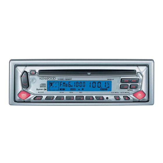
CD RECEIVER
KDC-1022
QQ
3 7 63 1515 0
KDC-122P
SERVICE MANUAL
Panel assy
(A64-3136-02): KDC-122P
OFF
TE
L 13942296513
Panel assy
(A64-3135-02): KDC-1022
OFF
DC cord
(E30-4784-05)
www
.
Front glass
(B10-4437-01): KDC-122P
KDC-122P
COMPACT
DIGITAL AUDIO
LOUD
SCAN
RDM
Front glass
(B10-4436-01): KDC-1022
KDC-1022
COMPACT
DIGITAL AUDIO
LOUD
SCAN
RDM
Mounting hardware assy
(J21-9716-03)
x
ao
u163
y
i
2 9
8
CD mechanism extension cord : W05-0618-00
Escutcheon
(B07-3022-02): KDC-122P
REP
CLK
ADJ
AUTO
Q Q
3
6 7
1 3
1 5
Escutcheon
(B07-3060-02): KDC-1022
REP
CLK
ADJ
AUTO
Lever
(D10-4589-04)
co
.
9 4
2 8
© 2003-6 PRINTED IN JAPAN
B53-0074-00 ( N ) 1445
CRSC
AME
AUD
0 5
8
2 9
9 4
2 8
CRSC
AME
AUD
Screw set
(N99-1719-05)
x2
m
9 9
9 9
Advertisement
Table of Contents

Related Manuals for Kenwood KDC-1022


Summary of Contents for Kenwood KDC-1022
- Page 1 (B10-4437-01): KDC-122P (B07-3022-02): KDC-122P KDC-122P COMPACT DIGITAL AUDIO CRSC LOUD SCAN AUTO L 13942296513 Panel assy Front glass Escutcheon (A64-3135-02): KDC-1022 (B10-4436-01): KDC-1022 (B07-3060-02): KDC-1022 KDC-1022 COMPACT DIGITAL AUDIO CRSC LOUD SCAN AUTO DC cord Mounting hardware assy Lever Screw set...
- Page 2 3 7 6 3 1 5 1 5 0 L 1 3 9 4 2 2 9 6 5 1 3 u 1 6 3...
-
Page 3: Components Description
KDC-1022/122P COMPONENTS DESCRIPTION 3 7 63 1515 0 SWITCH UNIT (X16-2370-12/13) Ref. No. Application/Functions Operation/Condition/Compatibility LCD driver & key matrix Key scan start When Q1 base goes Lo, key scan start. ELECTRIC UNIT (X25-9600-13/14) Ref. No. Application/Functions Operation/Condition/Compatibility System control µ-com System µ-com... - Page 4 KDC-1022/122P MICROCOMPUTER’S TERMINAL DESCRIPTION 3 7 63 1515 0 Pin No. Name Description Processing Operation AVREF1 Not used (connected to 9pin) ∆3 non communication : H IC10-DATA IC10, E2PROM data communication ∆3 non communication : H IC10-CLK IC10, E2PROM clock communication...
- Page 5 KDC-1022/122P MICROCOMPUTER’S TERMINAL DESCRIPTION 3 7 63 1515 0 Pin No. Name Description Processing Operation Power supply IC SW1 control 0 BA4911 SW1 Power supply IC output PS1-0 Audio 8V, P-CON PS1-2 PS1-1 PS1-0 P-CON P-ANT Power supply IC SW1 control 1...
-
Page 6: System Μ-Com Destination Type List
KDC-1022/122P MICROCOMPUTER’S TERMINAL DESCRIPTION 3 7 63 1515 0 System µ-com Destination type list TYPE2 TYPE1 TYPE0 MODEL NAME KDC-2024SA/SYA, 2024SG/SYG KDC-2022, 2022V, 202MR UPD780058GC499 RY-391CD, RX-491CD KDC-4023, 2023, 3023 KDC-122, 122S, 1022, 122P UPD780058GC501 KDC-1023, 1023S KDC-222, 222S KDC-3024G/YG, 307G/YG... - Page 7 KDC-1022/122P MICROCOMPUTER’S TERMINAL DESCRIPTION 3 7 63 1515 0 Pin No. Name Description Processing Operation Not used ASEL Audio output polarity switching terminal L : Reverse, H : Non reverse MSEL0 Destination type selection port (set 2bit) Order “MSEL 0” and “MSEL 1” Set up...
-
Page 8: Ic10 (Tda7513) -The Tuner Adjustment Method
KDC-1022/122P ADJUSTMENT 3 7 63 1515 0 1-3. Adjustment of FM_ANT & RF Coil 1. IC10 (TDA7513) -The Tuner adjustment method Voltage Check Point : S_METER-Check Land • When IC10 and its circumference are fixed, according to (PWB Side_B, around W572) the following order, it readjusts if needed. -
Page 9: Ic10 (Tda7513) Replacement -Parts Vs Adjustment Item Table
KDC-1022/122P ADJUSTMENT 3 7 63 1515 0 2. IC10 (TDA7513) Replacement -Parts vs Adjustment Item Table • When the parts in the following tables are exchanged, please readjust according to a table. • When other parts are exchanged, please perform only a check of operation. There is no necessity for readjustment. -
Page 10: Pc Board (Component Side View)
KDC-1022/122P PC BOARD (COMPONENT SIDE VIEW) 3 7 63 1515 0 CD PLAYER UNIT X32-5380-00 (J74-1485-12) L 13942296513 X32-5380-00 Refer to the schematic diagram for the values of resistors and capacitors. u163 Ref No. Address... - Page 11 KDC-1022/122P PC BOARD (FOIL SIDE VIEW) 3 7 63 1515 0 CD PLAYER UNIT X32-5380-00 (J74-1485-12) B/TE VREF VDET LDON A/TE TRCRS REFNV TRK IN TRK OUT D/ARF NRFDET FCS UP GCTL FCS DOWN VREF2 D.GND BU.5V D.OUT SLED IN...
- Page 12 KDC-1022/122P PC BOARD (FOIL SIDE VIEW) 3 7 63 1515 0 L 13942296513 Refer to the schematic diagram for the values of X25-9600-1x u163 Ref No. Address Ref No. Address Ref No. Address Ref No. Address Ref No. Address resistors and capacitors.
- Page 13 KDC-1022/122P PC BOARD 3 7 63 1515 0 (COMPONENT SIDE VIEW) (FOIL SIDE VIEW) SWITCH UNIT X16-2370-1x (J74-1285-32) SWITCH UNIT X16-2370-1x (J74-1285-32) DATAS L-CE ILL GND L 13942296513 X16-2370-1x Ref No. Address u163 Refer to the sche- matic diagram for the values of resistors and capacitors.
- Page 14 KDC-1022/122P CD PLAYER UNIT (X32-5380-00) 3 7 63 1515 0 D.GND C34 0.1 4.80V C32 0.1 BU+5V 1.25V 4.80V 2.40V 1.70V R100 C100 8EJE(SW2) 2200P 2200P 1000P 12EJE/SDET(SW3) 4.7K 4.80V LOE/LIM(SW4) 0.87pp PCK/NTLOCK/FCLK/STLD 2200P 2200P EFM/NFLOCK/CLDCK/STCK SENSE/RESY/FLAG/STOUT CLVS/VDET/CRC 4.80V DEMPH/TRCRSO/TEXTCRC...
- Page 15 KDC-1022/122P 3 7 63 1515 0 RFENV IOP+ IOP- R7 3.6K 3.3K C45 0.1 C44 1000P 1.25V C43 2200P 1.70V IREF PLLF2 0.047 0.95pp PLLF R39 100K 2.50V 0.91pp 0.87pp RFSW 1000P 4.7K 2.45V DSLF AVSS2 4.80V DVSS1 DVDD1 VDET 0-4.8V...
- Page 16 W405- FMAGCIN C256 Q251 R258 R261 R263 256,260 NAME 8.0V FMAGCVOUT KDC-122P (K) 0-13 100u50 TDA7386 180K W523 PW-ON KDC-1022 (M) 0-14 33u50 TDA7560 4.3K FMANTADJ FMRFADJ OSCGND R547 22 3.2V ∗ VCOE UPD780058GC501 Q10,20,70 2SC4081 S2V20 A or 3.8V ∗...
- Page 17 KDC-1022/122P 3 7 63 1515 0 E2P-ROM IC12 ∗ Q251 5.0V W158 ∗ D252 R258 ∗ 5.0V MUTE LOGIC ∗ POWER AMPLIFIRE ∗ W407 ∗ C252 R252 0.22u50 W161 4.7K ∗ W408 C253 ∗ 0.22u50 R253 4.7K L101 4.7uH CF54...
- Page 18 5.0V ILL-GND 5.0V TYPE REF LAMP+B CH-CON 5.0V LED+B R169 1K X16- 5.0V L-RES 5.0V 5.0V R167 100 L-DATAL 5.0V R166 1K L-CE R165 470 L-CLK R164 470 L-DATAS REMO SW5V R172 1K u163 PANEL ESD-G KDC-1022/122P (1/2) X25-9600-1x (3/3)
- Page 19 KDC-1022/122P SWITCH UNIT (X16-2370-1x) 3 7 63 1515 0 (B38-1079-05) : KDC-1022 (B38-1132-05) : KDC-122P L 13942296513 TP35 REMOTE ESD-GND SENSOR TP34 PANEL- ∗ TP24 KEY DETECT SW5V TP9 TP8 TP33 REMO TP27 R2 470 L-DATAS X25- TP28 R4 470...
- Page 20 TP15 u163 turned to the customer. • DC voltages are as measured with a high GND LINE impedance voltmeter. Values may vary slightly B LINE due to variations between individual instru- ments or/and units. KDC-1022/122P (2/2) X16-2370-1x (2/2)
-
Page 21: Exploded View (Mechanism)
KDC-1022/122P EXPLODED VIEW (MECHANISM) 3 7 63 1515 0 DPU1 L 13942296513 DFPC1 (X32) φ : N09-4460-05 M1.7x8.5 : N09-4472-05 : N09-6004-05 M1.7x2.5 : N09-6007-05 M2x2 u163 φ : N09-6051-05 2x6(BLK) : N19-2163-04 1.6 WASHER : N39-2020-46 M2x2 : N09-6108-05 M2x3.5... -
Page 22: Exploded View (Unit)
KDC-1022/122P EXPLODED VIEW (UNIT) 3 7 63 1515 0 M3x8 : N30-3008-46 DME1 φ 2x6 : N80-2006-46 φ 2x8 (BLK) : N80-2008-45 φ 3x5 : N83-3005-46 φ 3x10 : N80-3010-46 φ 3x20 : N83-3020-46 φ 2.6x6 : N86-2606-46 (X16-) L 13942296513... -
Page 23: Parts List
B38-1132-05 LIQUID CRYSTAL (POSI) C506 CK73GB1C104K CHIP C 0.10UF C507 CD04AT1A330M ELECTRO 33UF 10WV CK73GB1H102K CHIP C 1000PF C2,3 CK73GB1E473K CHIP C 0.047UF K C508 CD04AT1A220M ELECTRO 22UF 10WV K : KDC-1022 K1 : KDC-122P Indicates safety critical components. - Page 24 J 1/10W R116 RK73GB2A103J CHIP R J 1/10W E40-9550-05 FLAT CABLE CONNECTOR (22P) R117 RK73GB2A102J CHIP R 1.0K J 1/10W E04-0312-05 RF COAXIAL CABLE RECEPTACLE R118 RK73GB2A103J CHIP R J 1/10W K : KDC-1022 K1 : KDC-122P Indicates safety critical components.
- Page 25 J 1/10W R525 RK73GB2A821J CHIP R J 1/10W D264 D1F60 DIODE R526 RK73GB2A562J CHIP R 5.6K J 1/10W D264 DIODE R527 RK73GB2A104J CHIP R 100K J 1/10W D265,266 AM01Z DIODE K : KDC-1022 K1 : KDC-122P Indicates safety critical components.
- Page 26 CK73GB1H102K CHIP C 1000PF RK73GB2A103J CHIP R J 1/10W C45-47 CK73GB1C104K CHIP C 0.10UF R52,53 RK73GB2A472J CHIP R 4.7K J 1/10W RK73GB2A133J CHIP R J 1/10W CK73GB1H682K CHIP C 6800PF K : KDC-1022 K1 : KDC-122P Indicates safety critical components.
- Page 27 GEAR D13-2154-04 GEAR D13-2155-04 WORM D13-2156-14 GEAR D13-2157-04 GEAR D13-2158-04 GEAR D13-2168-04 GEAR D13-2171-04 GEAR D13-2172-03 RACK (GEAR) D14-0759-04 ROLLER D21-2382-04 SHAFT u163 D23-0954-04 RETAINER D39-0246-05 DAMPER G01-3072-04 EXTENSION SPRING K : KDC-1022 K1 : KDC-122P Indicates safety critical components.
-
Page 28: Specifications
KENWOOD ELECTRONICS UK LIMITED P.O. Box 61318, Jebel Ali, Dubai, U.A.E. Kenwood House, Dwight Road, Watford, Herts, WD18 9EB, United Kingdom KENWOOD ELECTRONICS (THAILAND) CO., LTD. KENWOOD ELECTRONICS DEUTSCHLAND GMBH 2019 New Pechburi Road, Bangkapi, Huaykwang, Bangkok, 10320 Thailand Rembrücker-Str.