Sony MB-8N Operating Instructions Manual
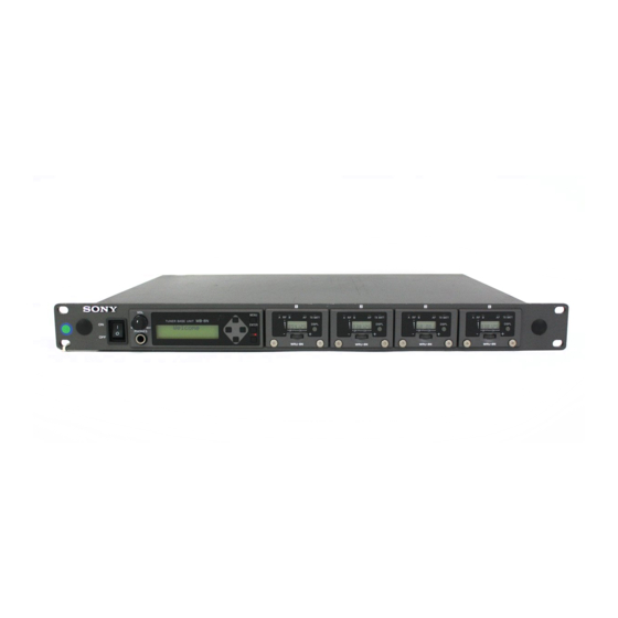
Tuner base unit
Hide thumbs
Also See for MB-8N:
- Features & specifications (6 pages) ,
- User manual (28 pages) ,
- Operation manual (20 pages)

Related Manuals for Sony MB-8N


Summary of Contents for Sony MB-8N
- Page 1 3-619-690-13(2) Tuner Base Unit Operating Instructions MB-8N 2002 Sony Corporation...
- Page 2 The model and serial numbers are located at the rear. electric shock to persons. Record the serial number in the space provided below. Refer to them whenever you call upon your Sony dealer regarding this product. This symbol is intended to alert the user to the presence of important operating and Model No.
- Page 3 800 - 820 MHz Switzerland 800 - 820 MHz Finland 800 - 814 MHz Iceland 800 - 814 MHz Hereby, Sony Corporation, declares that this MB-8N is in compliance with the essential requirements and other relevant provisions of Directive 1999/5/EC.
-
Page 5: Table Of Contents
Channel Plan ............. 8 Using the CD-ROM ........... 8 Trademarks ............10 Location of Parts and Controls ..... 11 MB-8N Tuner Base Unit ......... 11 WRU-8N Tuner Unit (Option) ......14 Installing and Removing a WRU-8N ....16 Connections ........... 17 Basic Connections ........... -
Page 6: Precautions
• Avoid using in very humid or dusty places, because such use may shorten the life of the tuner. About fan replacement, contact your Sony dealer. • To avoid degradation of the signal-to-noise ratio, do not use the tuner in noisy places or in locations... -
Page 7: Overview
125-kHz steps of Sony original channel plan in the range of TV channels 66 and 67......................................... 1) When each MB-8N Tuner Base Unit has four WRU-8N UHF Synthesizer Tuner Units installed. Note that the receiving system consisting of the MB-8N and the AU model ot WRU-8N allows you to simultaneously use a maximum of 12 channels in one area. -
Page 8: Channel Plan
Rack mounting For the installation procedure, see “Installation” on the The MB-8N can be mounted in an EIA standard 19- next page. inch rack (1U size). For detailed information on the MB-8N Network Controller, refer to the User’s Guide for the MB-8N Network... - Page 9 To change, click the Browse button and select the Installation destination location in the dialog box which appears. • If the MB-8N Network Controller is already set up, uninstall the existing version before continuing with Click the Next button. the installation. (See the next section “To uninstall the installed files”.)
-
Page 10: Trademarks
Channel plan The channel plan shown in the Frequency Lists on the supplied CD-ROM may include currently unsupported features. For the latest information, refer to your Sony service representative. Trademarks • Pentium is a registered trademark of Intel Corporation or its subsidiaries in the United States and other countries. -
Page 11: Location Of Parts And Controls
Location of Parts and Controls MB-8N Tuner Base Unit Front panel 1 Power switch 2 VOL control 1 MB-8N display (see next page) 3 Blanking panels MENU A RF TX BATT MB-8N TUNER BASE UNIT ENTER DSPL LOCAL PHONES WRU-8N... - Page 12 Location of Parts and Controls 6 LOCAL/REMOTE selector button 1 MB-8N display Hold this down for three seconds to switch between 2 T/t buttons local and remote modes. 3 MENU button Local mode: Select this mode to make and check 1 Menu name settings on the operating panel of this unit.
-
Page 13: Rear Panel
When using a cascade connection, set the RF 100 m (330 ft), use a hub between the computer and attenuator for the MB-8N units to which no antenna is this unit. directly connected to “OFF.”... -
Page 14: Wru-8N Tuner Unit (Option)
3 DSPL (display) button Pressing this button toggles the WRU-8N display (next 1 Fixing screws page) between the group/channel (GP/CH) display and These fix the WRU-8N unit to the MB-8N unit (this frequency display. unit). 2 Jog dial The jog dial has two functions, as follows. - Page 15 1 WRU-8N display 6 RF (radio frequency input) level display 7 RF (radio frequency input) indicator Of the antennas A and B, the indicator lights for that 1 AF level display with the better receiving conditions, appearing as a 2 AF indicator number of segments.
-
Page 16: Installing And Removing A Wru-8N
Fully loosen the fixing screws. Holding the sides of the WRU-8N, insert it in the slot, and press in until the panel is flush with the Holding the fixing screws in both hands, slowly MB-8N operating panel. pull out. -
Page 17: Connections
UHF antenna UHF antenna AN-820A AN-820A Mixer or amplifier ANTENNA B ANTENNA A MB-8N AUDIO OUT a) ~ AC IN a) AC power cord (supplied) b) 50-ohm coaxial cable (RG-5 type, RG-212 type or equivalent recommended) c) XLR cable... -
Page 18: Cascade Connection
Mixer d) Category 5 LAN cable (straight cable not exceeding 100 m (330 ft)) e) For the MB-8N units to which no antenna is directly connected, set the antenna RF attenuator to “OFF” (0 dB). f) If you install the MB-8N Network Controller software on more than one computer on the network, do not start the software on more than one computer at a time. -
Page 19: Settings
The setting operation depends on the operation mode For details of settings using the MB-8N Network Controller, of this unit, as follows. refer to the User’s Guide for MB-8N Network Controller on Local mode: You can set or check settings using the the supplied CD-ROM. - Page 20 Settings Local menu Submenus Submenus/Settings Settings Root menu (Second level) (Fourth level) (Third level) (First level) Local Menu MB Config ANTENNA ATT AntA ATT [dB] MB WRU NET ETC ATT DC AF MON AntA AntB ALL AntB ATT [dB] AntAB ATT [dB] ANT DC OUT AF LEVEL 1CH AF LEVEL...
- Page 21 Remote menu Root menu MB WRU NET Voltage output Antenna RF Audio output level Headphone output to antenna attenuation Ant ATT [dB] Ant DC9V OUT AF LEVEL Headphone Slot selection User name of WRU-8N RF squelch for WRU-8N Tone/noise squelch in slot 1 in slot 1 for WRU-8N in slot 1...
-
Page 22: Using The Menus
“[ ],” skip to step 9. Press the power switch, to power on this unit. Press the T/t buttons, to select the desired item. The MB-8N display shows a “Welcome” message, then displays the menu (Local or Remote menu) for the currently selected mode. - Page 23 Selecting a change of settings when replacing a WRU-8N unit To return to the previous display Press the MENU button. The MB-8N unit saves the settings for all installed WRU-8N units. Repeat from step 2. When powered on, if it detects a WRU-8N unit with different settings from that previously installed, a Successive submenu settings appear.
-
Page 24: List Of Settings
Settings List of Settings Tuner base unit setting items The MB submenu provides setting items relating to the MB-8N unit (this unit). For details of individual items, see the page numbers shown in parenthesis. Submenu Setting Setting items Setting refers to... - Page 25 Factory default: 0. 0. 0. 0 a)Set this so as not to conflict with a computer, router, or other MB-8N units on the network. For more details of the setting, with examples, refer to the User’s Guide for MB-8N Network Controller.
- Page 26 • AF (audio output level) • MON (audio output to headphone) WRU: Following settings for the WRU- • Group (GP) • Channel (CH) • RSQ (RF squelch) • SQ (tone squelch and noise squelch) INIT: All the settings relating to MB-8N and WRU-8N...
-
Page 27: Details Of Settings
• MB-8N unit directly connected to the antenna: as above (“When using the optional AN-820A UHF Notes on headphones output settings • When you are using the MB-8N connected to the antenna”) network, switching the control mode from local to •... - Page 28 IP Turn them off when looking for external interference or noise. addresses for the computer and each MB-8N unit at intervals of 2 or 3 address values. Note While this unit is in receiving standby or is receiving...
- Page 29 Set the group for slot 1 in the second MB-8N unit to the same group as the first MB-8N unit. Search for free channels within group, and For details of group settings, see “Channel Settings”...
-
Page 30: Channel Settings
WRU-8N 3,4,5,6,7 CE67 Press the power switch, powering on the unit. The MB-8N display shows a “Welcome” message, then displays the menu (Local or Remote menu) for the currently selected mode. Note Powering on may cause noise in audio output, so... - Page 31 6-3 Press the jog dial. This switches to the frequency display, and the display flashes. Press the MENU button on the MB-8N unit to return 6-4 Turn the jog dial clockwise (+) or to the previous display. counterclockwise (–), to select the channel.
-
Page 32: Appendixes
Appendixes Appendixes Error Messages In addition to normal indications, the MB-8N display shows the following error messages. Message Meaning What to do Warning01 TUNER x This message appears if there is a When starting in remote mode: ERROR communications problem between the MB-8N There is the possibility that the WRU-8N in the unit (this unit) and the WRU-8N unit. -
Page 33: Connector Specifications
Remove the feet of the tuner before mounting it on Pin number Signal name Description a rack. CH1 OUT Audio signal output of WRU- 8N in slot 1 Mount the tuner on the rack using screws that are CH2 OUT Audio signal output of WRU- at least 12 mm ( inches) long and that match the... -
Page 34: Principal Specifications
Appendixes Network Principal Specifications 10BASE-T connector Tuner (with WRU-8N) RJ-45, 8-pole Reception type Space diversity General Circuit system Dual conversion superheterodyne Operating frequency range Power requirements CE/AU models 758 to 862 MHz CE/AU models U models 566 to 806 MHz 100 to 240 V AC, 50/60 Hz Reception frequencies U models... - Page 35 Sony Corporation...