Table of Contents

Related Manuals for Panasonic DMR-EZ47VP


Summary of Contents for Panasonic DMR-EZ47VP
-
Page 1: Dvd Recorder
ORDER NO.CHM0704017CE DVD Recorder DMR-EZ47VP Model No. DMR-EZ475VP Vol. 1 Colour (K).......Black Type © 2007 Matsushita Electric Industrial Co., Ltd. All rights reserved. Unauthorized copying distribution is a violation of law. -
Page 2: Table Of Contents
DMR-EZ47VP / DMR-EZ475VP CONTENTS Page Page 1 Safety Precaution 11.5. Analog Timer Block Diagram 1.1. General guidelines 11.6. System Control & Servo Block Diagram 1.2. Caution for fuse replacement 12 Schematic Diagram 2 Warning 12.1. Interconnection Schematic Diagram 2.1. Prevention of Electrostatic Discharge (ESD) to 12.2. - Page 3 DMR-EZ47VP / DMR-EZ475VP 14.2. Abbreviations 15.1. Exploded Views 15 Parts and Exploded Views 15.2. Replacement Parts List...
-
Page 4: Safety Precaution
DMR-EZ47VP / DMR-EZ475VP 1 Safety Precaution 1.1. General guidelines 1. When servicing, observe the original lead dress. If a short circuit is found, replace all parts which have been overheated or damaged by the short circuit. 2. After servicing, see to it that all the protective devices such as insulation barriers, insulation papers shields are properly installed. -
Page 5: Warning
DMR-EZ47VP / DMR-EZ475VP 2 Warning 2.1. Prevention of Electrostatic Discharge (ESD) to Electrostatic Sensitive (ES) Devices Some semiconductor (solid state) devices can be damaged easily by static electricity. Such components commonly are called Electrostatic Sensitive (ES) Devices. Examples of typical ES devices are integrated circuits and some field-effect transistor-sand semiconductor "chip"... -
Page 6: Precaution Of Laser Diode
DMR-EZ47VP / DMR-EZ475VP 2.2. Precaution of Laser Diode... -
Page 7: Service Caution Based On Legal Restrictions
DMR-EZ47VP / DMR-EZ475VP 2.3. Service caution based on legal restrictions 2.3.1. General description about Lead Free Solder (PbF) The lead free solder has been used in the mounting process of all electrical components on the printed circuit boards used for this equipment in considering the globally environmental conservation. -
Page 8: Service Navigation
DMR-EZ47VP / DMR-EZ475VP 3 Service Navigation 3.1. Service Information 3.2. Caution for DivX... -
Page 9: Specifications
DMR-EZ47VP / DMR-EZ475VP 4 Specifications... -
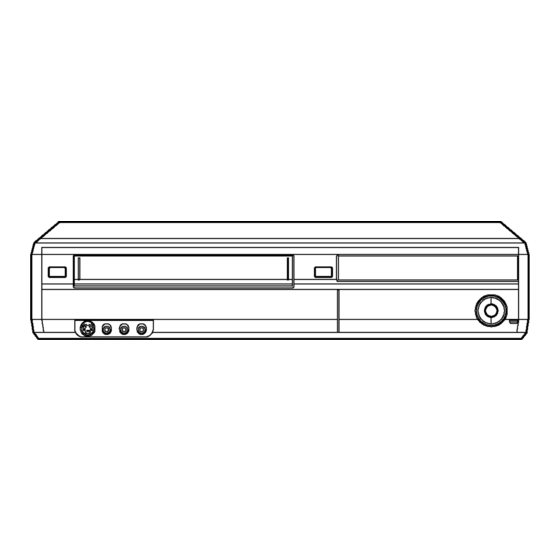
Page 10: Location Of Controls And Components
DMR-EZ47VP / DMR-EZ475VP 5 Location of Controls and Components 5.1. Each Buttons... - Page 11 DMR-EZ47VP / DMR-EZ475VP...
-
Page 12: Operation Instructions
DMR-EZ47VP / DMR-EZ475VP 6 Operation Instructions 6.1. (DVD) Taking out the Disc from RAM-Drive Unit when the Disc cannot be ejected by OPEN/CLOSE button 6.1.1. (DVD) Forcible Disc Eject 6.1.1.1. (DVD) When the power can be turned off. 1. Turn off the power and press [STOP], [CH UP] keys on the front panel simultaneously for 5 seconds. - Page 13 DMR-EZ47VP / DMR-EZ475VP 1. Turn off the power and pull out AC cord. 2. Remove the Top Case. 3. Push in SLIDE CAM by Eject Pin(JSJ0484) or minus screw driver (small) to eject tray slightly. 4. Push out Tray by Eject Pin (JZS0484) or minus screw driver (small).
-
Page 14: Vhs) Removing Cassette Tape Manually
DMR-EZ47VP / DMR-EZ475VP 6.2. (VHS) Removing Cassette Tape manually When the cassette tape could not be uninstalled from an electrical malfunction, there are 2 ways to remove a cassette tape. 6.2.1. (VHS) Removal by compulsory unloading. If Service Mode can be activated when the power can not be turned on, this operation is able. - Page 15 DMR-EZ47VP / DMR-EZ475VP 7. Set the Position Switch to EJECT POSITION certainly and attach the mechanism to chassis as shown below. 3. Rotate the Main Cam Gear counter-clockwise until just before the unloading will be completed as shown below. .
-
Page 16: Service Mode
DMR-EZ47VP / DMR-EZ475VP 7 Service Mode 7.1. (DVD) Self-Diagnosis and Special Mode Setting 7.1.1. (DVD) Self-Diagnosis Functions Self-Diagnosis Function provides information for errors to service personnel by “Self-Diagnosis Display” when any error has occurred. U**, H** and F** are stored in memory and held. - Page 17 DMR-EZ47VP / DMR-EZ475VP Error Code Diagnosis contents Description Monitor Display Automatic FL display Serial Communication Error Please confirm Serial Communication No display between VHS Microprocessor terminal of Microprocessor. and Timer Microprocessor. NOTE: If F09 appears just after updating Firmware, pull off and insert AC plug, then it will disappear.
- Page 18 DMR-EZ47VP / DMR-EZ475VP Error Code Diagnosis contents Description Monitor Display Automatic FL display PLEASE Unit is in termination process Unit is in termination process now. No display WAIT “BYE” is displayed and power will be turned off. In case “Quick Start” of setup menu is ON, it is displayed in restoration operation for AC off.
- Page 19 DMR-EZ47VP / DMR-EZ475VP Item FL display Key operation Mode name Description Front Key Aging Contents (Example):...
- Page 20 DMR-EZ47VP / DMR-EZ475VP Item FL display Key operation Mode name Description Front Key Demonstration Ejection of the disc is prohibited. *When lock the tray. When the power is on, press lock/unlock The lock setting is effective until unlocking the [STOP] and [POWER] keys...
- Page 21 DMR-EZ47VP / DMR-EZ475VP 7.1.3. (DVD) Service Modes at a glance Service mode setting: While the power is off, press [STOP], [VHS to DVD COPYING] and [OPEN / CLOSE] simultaneously for five seconds. Item FL display Key operation Mode name Description...
- Page 22 DMR-EZ47VP / DMR-EZ475VP Item FL display Key operation Mode name Description (Remote controller key) Audio Pattern Output The audio pattern stored in the internal Initial mode (Audio 48kHz) Press [2] [3] in service mode. memory is output (Lch: 1kHz/-18dB) (Rch: 400Hz/-18dB) *Audio sound clock switching operation of Audio 44.1kHz/48kHz switching...
- Page 23 DMR-EZ47VP / DMR-EZ475VP Item FL display Key operation Mode name Description (Remote controller key) RAM Drive Last Error RAM Drive error code display. 1. Error Number is displayed for 5 Press [4] [2] in service mode. *For details about the drive error code, refer seconds.
- Page 24 DMR-EZ47VP / DMR-EZ475VP Item FL display Key operation Mode name Description (Remote controller key) Laser power confirmation Drive state is judged based on difference into RAM between laser power value at shipping and Drive in service mode. (Other present laser power value.
- Page 25 DMR-EZ47VP / DMR-EZ475VP Item FL display Key operation Mode name Description (Remote controller key) Display the Error History Display the Error History stored on the unit. Display reason of error for 5 Press [6] [5] in service mode. seconds. Then press [0] [1] ~ [1] [9], the past 19 error histories are displayed.
-
Page 26: Vhs) Self-Diagnosis And Special Mode Setting
DMR-EZ47VP / DMR-EZ475VP 7.2. (VHS) Self-Diagnosis and Special Mode Setting 7.2.1. (VHS) Self-Diagnosis Functions This model has a self-diagnosis and display function. If the VHS section detects trouble during installation or during use, one of the following Error Codes will automatically appear in the display on VHS side. Error Codes are displayed in the form of a single English letter followed by two numbers, as for example "H01". - Page 27 DMR-EZ47VP / DMR-EZ475VP 7.2.2. (VHS) Special Modes Setting Item FL display Key operation Mode name Description Front Key Tracking Center Tape Tracking is adjusted to center No display. During PLAYBACK, press [CH UP] FIX position. DOWN] keys simultaneously. VHS Service Mode...
- Page 28 DMR-EZ47VP / DMR-EZ475VP Service Contents Contents of Indication on minute Contents of Indication on second Remarks Number Indication for the Mechanism position Ordering for the Motors There are next conditions in this inner data (Real time) (Real time) mode for enable the mechanism...
- Page 29 DMR-EZ47VP / DMR-EZ475VP 7.2.4.2. (VHS) Condition for clearing the self-diagnosis history 1. A case of that press the STOP key and the EJECT key simultaneously over 5 seconds. 7.2.4.3. (VHS) Indication of the self-diagnosis history. 1. The self-diagnosis histories and its supplementary data could be indicated on the FIP with Service mode of number from 3 to 2.
- Page 30 DMR-EZ47VP / DMR-EZ475VP <Supplementary Data 4> (LM Information) Result of request of driving Loading Motor. Display Description There was no change of mechanism position. (Loading Motor was OFF) There was some change of mechanism position. (Loading Motor was ON) 7.2.5.
- Page 31 DMR-EZ47VP / DMR-EZ475VP Tape Type The aim of Tape position between the starting edge and the finishing edge 60 min. or less type (Large Hub) The Tape position is divided into 6 stages between the Tape beginning edge: "A " and the Tape end edge: "5".
-
Page 32: Service Fixture & Tools
DMR-EZ47VP / DMR-EZ475VP 8 Service Fixture & Tools (For DVD) Part Number Description Compatibility RFKZ0168 Extension Cable (Power & Digital I/F P.C.B. - FAN / 3 Pin) Same as E50 / ES30V / ES40V Series RFKZ0169 Extension Cable (Power & Digital I/F P.C.B. - DVD Drive / 4 Pin) -
Page 33: Assembling And Disassembling Instructions
DMR-EZ47VP / DMR-EZ475VP 9 Assembling and Disassembling Instructions 9.1. Disassembly Flow Chart The following chart is the procedure for disassembling the casing and inside parts for internal inspection when carrying out the servicing. To assemble the unit, reverse the steps shown in the chart below. -
Page 34: Positions
DMR-EZ47VP / DMR-EZ475VP 9.2. P.C.B. Positions... -
Page 35: Caution With Inserting Cassette Tape When Disassembling The Unit
DMR-EZ47VP / DMR-EZ475VP 9.3. Caution with inserting cassette tape when disassembling the unit Note1: For description of the disassembling procedure, see the section 9.4. Note2: Video Cassette might not enter when a strong lighting is applied to VHS Mechanism when Video Cassette is inserted. Please... -
Page 36: Top Cover
DMR-EZ47VP / DMR-EZ475VP arrow. 9.4. Top cover 1. Remove the 4 screws (A) and 3 screws (B). 2. Slide Top cover rearward and open the both ends at rear side of the Top cover a little and lift the Top cover in the direction of the arrows. -
Page 37: Front (L) P.c.b. & Front (R)
DMR-EZ47VP / DMR-EZ475VP 9.6. Front (L) P.C.B. & Front (R) P.C.B. 9.6.1. Front (L) P.C.B. 1. Remove 4 tabs to remove Front (L) P.C.B.. 9.6.2. Front (R) P.C.B. 1. Remove 3 screws (A) and tab to remove Front (R) P.C.B.. - Page 38 DMR-EZ47VP / DMR-EZ475VP 9.6.4. Assembly of Blinder Panel and Blinder Spring Step 3 : Slide Blinder Panel into shaft hole of Front Panel. Step 1 : Insert Blinder Spring into shaft of Blinder Panel. Step 4 : Slide down Blinder Panel to touch the shaft on top of the rib.
-
Page 39: Dvd Drive
DMR-EZ47VP / DMR-EZ475VP 9.7. DVD drive 9.8. SD/DV Jack P.C.B. 1. Remove 3 Screws (A). 1. Remove 2 Screws (A) to remove SD/DV jack P.C.B.. 2. Disconnect FFC and Wire with connector, remove DVD drive. -
Page 40: Rear Panel, Fan Motor
DMR-EZ47VP / DMR-EZ475VP 9.9. Rear Panel, Fan Motor 9.10. Digital P.C.B. 9.9.1. Only Fan motor 1. Disconnect Fan Connector. 2. Remove 2 Screws (A) to Remove Fan Motor. 1. Remove 2 Screws (A) and 2 FFCs. And lift up Digital P.C.B. slightly so to disconnect connectors to remove Digital P.C.B.. -
Page 41: Vhs Mechanism Unit
DMR-EZ47VP / DMR-EZ475VP 9.11.1. Caution for attaching VHS 9.11. VHS Mechanism Unit Mechanism Unit 1. Disconnect 3 Connectors (P1531, P2501 and P4002). 1. Because Position SW should be set to "Eject Position", 2. Remove 3 Screws (A), Screw (B) , Screw (C) and Screw refer to fig.(A) and set the position switch so that the boss... -
Page 42: Main P.c.b
DMR-EZ47VP / DMR-EZ475VP 9.12. Main P.C.B. 9.13. Digital I/F P.C.B. 1. Disconnect 4 Connectors. 1. Remove 4 Screws (A) to remove DVD angle. 2. Remove 2 Screws (A) and remove Main P.C.B. 2. Disconnect 4 Connectors. 3. Remove the Screw (B) to remove Digital I/F P.C.B. after... -
Page 43: Measurements And Adjustments
DMR-EZ47VP / DMR-EZ475VP 10 Measurements and Adjustments 10.1. Service Positions Note: For description of the disassembling procedure, see the section 9. 10.1.1. Checking and Repairing of Power & Digital I/F P.C.B. - Page 44 DMR-EZ47VP / DMR-EZ475VP 10.1.2. Checking and Repairing of Main P.C.B.
- Page 45 DMR-EZ47VP / DMR-EZ475VP 10.1.3. Checking and Repairing of Digital P.C.B.
- Page 46 DMR-EZ47VP / DMR-EZ475VP 10.1.4. Checking and Repairing of DVD...
-
Page 47: Caution For Replacing Parts
DMR-EZ47VP / DMR-EZ475VP 10.2. Caution for Replacing Parts 10.2.1. Notice after replacing Digital P.C.B. [TM L1] is displayed, after replacing Digital P.C.B. Once power off, and start up again. 10.2.2. Items that should be done after replacing parts... - Page 48 DMR-EZ47VP / DMR-EZ475VP...
- Page 49 DMR-EZ47VP / DMR-EZ475VP...
-
Page 50: Standard Inspection Specifications After Making Repairs
DMR-EZ47VP / DMR-EZ475VP 10.3. Standard Inspection Specifications after Making Repairs After making repairs, we recommend performing the following inspection, to check normal operation. - Page 51 DMR-EZ47VP / DMR-EZ475VP Use the following checklist to establish the judgement criteria for the picture and sound. Item Contents Check Item Contents Check Block noise Distorted sound Crosscut noise Noise (static, background noise, etc.) Dot noise The sound level is too low.
- Page 52 DMR-EZ47VP / DMR-EZ475VP...
-
Page 97: Appendix For Schematic Diagram
DMR-EZ47VP / DMR-EZ475VP 14 Appendix for Schematic Diagram 14.1. Voltage and Waveform Chart Note) Circuit voltage and waveform described herein shall be regarded as reference information when probing defect point, because it may differ from an actual measuring value due to difference of Measuring instrument and its measuring condition and product itself. - Page 98 DMR-EZ47VP / DMR-EZ475VP 14.1.2. Main P.C.B. IC1511 IC1512 IC2001 Ref No. MODE PLAY STOP IC2501 Ref No. MODE 12.2 16.1 PLAY 12.2 16.2 STOP 12.2 16.2 Ref No. IC2501 MODE 12.2 PLAY 12.2 STOP 12.2 IC3001 Ref No. MODE PLAY...
- Page 99 DMR-EZ47VP / DMR-EZ475VP IC4801 Ref No. MODE 12.5 PLAY 12.5 STOP 12.5 IC4802 IC4803 Ref No. MODE 12.5 12.6 PLAY 12.5 12.6 STOP 12.5 12.6 IC4804 Ref No. MODE PLAY STOP IC4804 Ref No. MODE PLAY STOP IC4805 IC4806 Ref No.
- Page 100 DMR-EZ47VP / DMR-EZ475VP Q1501 Q1502 Q3001 Q3003 Q3004 Ref No. MODE PLAY STOP Q3901 Q3902 Q4001 Q4002 Ref No. Q4081 MODE -19.4 10.4 -28.1 -19.4 -28.1 -0.6 PLAY STOP Q4084 Q4501 Q4502 Q4801 Q4802 Ref No. MODE 12.6 12.5 11.8 -0.6...
- Page 101 DMR-EZ47VP / DMR-EZ475VP 14.1.3. Front (L) P.C.B. IC7701 Ref No. MODE STOP 14.1.4. Front (R) P.C.B. QR27501 QR27503 QR27505 Ref No. MODE STOP 14.1.5. P56001 Connector P56001 Ref No. MODE PLAY STOP P56001 Ref No. MODE PLAY STOP P56001 Ref No.
- Page 102 DMR-EZ47VP / DMR-EZ475VP 14.1.6. Waveform Chart IC6001-19 PLAY IC6001-18(TW2001) REC IC6001-50 REC/PLAY IC6001-52 REC/PLAY IC6001-79 FF/REW 5.0Vp-p (5msec.div.) 5.0Vp-p (10msec.div.) 2.2Vp-p (20usec.div.) 2.2Vp-p (20usec.div.) 5.0Vp-p (1msec.div.) IC6001-86(TL2015) PLAY IC6001-95 REC IC6001-80 FF/REW IC6001-90 REC IC6001-94 REC 0.7Vp-p (0.5msec.div.) 2.4Vp-p (10msec.div.) 5.0Vp-p (1msec.div.)
- Page 103 DMR-EZ47VP / DMR-EZ475VP IC1110-5 STOP T1110-1 STOP 360Vp-p (5usec.div) 20Vp-p (2msec.div) T1130-4 STOP T1110-4 STOP T1130-6 STOP T1130-8 STOP 20Vp-p (2msec.div) 36Vp-p (5usec.div) 300Vp-p (5usec.div) 25Vp-p (5usec.div) P37101-78,80 REC/PLAY P37101 -60 REC/PLAY P37101 -64 REC/PLAY P37101-56 REC/PLAY 0.8Vp-p (1msec.div) 0.8Vp-p (20usec.div.) 1.0Vp-p (20usec.div.)
-
Page 104: Abbreviations
DMR-EZ47VP / DMR-EZ475VP 14.2. Abbreviations INITIAL/LOGO ABBREVIATIONS ERROR TORQUE CONTROL ERROR TORQUE CONTROL 14.2.1. DVD REFERENCE ENCSEL ENCODER SELECT INITIAL/LOGO ABBREVIATIONS ETMCLK EXTERNAL M CLOCK (81MHz/40.5MHz) A0~UP ADDRESS ETSCLK EXTERNAL S CLOCK (54MHz) ACLK AUDIO CLOCK FBAL FOCUS BALANCE AD0~UP... - Page 105 DMR-EZ47VP / DMR-EZ475VP INITIAL/LOGO ABBREVIATIONS INITIAL/LOGO ABBREVIATIONS READ ENABLE VBLANK V BLANKING RFENV RF ENVELOPE COLLECTOR POWER SUPPLY RF PHASE DIFFERENCE OUTPUT VOLTAGE (CD-ROM) REGISTER SELECT VCDCONT VIDEO CD CONTROL (TRACKING RSEL RF POLARITY SELECT BALANCE) RESET DRAIN POWER SUPPLY VOLTAGE...
- Page 106 DMR-EZ47VP / DMR-EZ475VP 14.2.2. VHS 3-1. ABBREVIATIONS 4.43 NTSC L 443NT [L] BILINGUAL BILINGUAL L A. COMP AUDIO COMPONENT SIGNAL BIL [L] BIL. [H] BILINGUAL H A. COMPO AUDIO COMPONENT SIGNAL BIL/M1 [L] BILINGUAL L AUDIO DUBBING PAUSE L A. D.P [L]...
- Page 107 DMR-EZ47VP / DMR-EZ475VP CYL GND CYLINDER GND FULL. E. 12V FULL ERASE 12V D.F.M. REC [H] DELAIED FM RECORDING H GND [A] GND (ANALOG) D. FM REC [L] DELAIED FM RECORDING L GND [TU] GND (TUNER) D. GND DIGITAL GND GND/N.
- Page 108 DMR-EZ47VP / DMR-EZ475VP POWER OFF H LINE IN [R] LINE INPUT (R) P-OFF [H] POWER OFF L LINE OUT [L] LINE OUTPUT (L) P-OFF [L] LINE OUT [R] LINE OUTPUT (R) P. FAIL POWER FAILURE DETECT LP H POWER OFF H LP [H] P.
- Page 109 DMR-EZ47VP / DMR-EZ475VP RF OUT RF OUTPUT SYSCON 5V SYSTEM CONTROL 5V RF Y RF LUMINANCE SIGNAL SYSTEM SYSTEM SW RF. Y. IN RF LUMINANCE SIGNAL INPUT T-PHOTO TAKE-UP PHOTO TRANSISTOR RF. Y. OUT RF LUMINANCE SIGNAL OUTPUT T-RL. PLS TAKE-UP REEL PULSE ROTAR.
-
Page 110: Parts And Exploded Views
DMR-EZ47VP / DMR-EZ475VP 15 Parts and Exploded Views 15.1. Exploded Views 15.1.1. Casing Parts & Mechanism Section1... - Page 111 DMR-EZ47VP / DMR-EZ475VP 15.1.2. Casing Parts & Mechanism Section 2...
-
Page 112: Vhs Mechanism Section
DMR-EZ47VP / DMR-EZ475VP 15.1.3. VHS Mechanism Section... - Page 113 DMR-EZ47VP / DMR-EZ475VP 15.1.4. Packing & Accessories Section...
-
Page 114: Replacement Parts List
DMR-EZ47VP / DMR-EZ475VP 15.2. Replacement Parts List Notes: Ref. No. Part No. Part Name & Remarks Description *Important safety notice: C3011 F1H1C104A071 16V 0.1U C3012 F2A0J470A824 6.3V 47P Components identified mark have special C3013 F2A1C100B099 16V 10P characteristics important for safety. - Page 115 DMR-EZ47VP / DMR-EZ475VP Ref. No. Part No. Part Name & Remarks Ref. No. Part No. Part Name & Remarks Description Description C4004 ECJ1VB1H182K 50V 1800P C4823 ECJ1VB1H103K 50V 0.01U C4005 F2A0J220A878 6.3V 22P C4827 ECJ1VF1C104Z 16V 0.1U C4006 F2A1H4R7B033 50V 4.7U...
- Page 116 DMR-EZ47VP / DMR-EZ475VP Ref. No. Part No. Part Name & Remarks Ref. No. Part No. Part Name & Remarks Description Description D7506 B0AACK000004 DIODE P2501 K1MN07A00019 CONNECTOR(7P) D7507 MAZ4091NHF DIODE P2571 K1KA08A00355 CONNECTOR(8P) P3001 K1MN09A00022 CONNECTOR(9P) DP7501 A2BD00000168 DISPLAY TUBE...
- Page 117 DMR-EZ47VP / DMR-EZ475VP Ref. No. Part No. Part Name & Remarks Ref. No. Part No. Part Name & Remarks Description Description R3002 ERJ3GEYJ622V 1/10W 6.2K R4518 ERJ3GEYJ622V 1/10W 6.2K R3003 ERDS2TJ471T 1/4W 470 R4519 ERJ3GEYJ753V 1/10W 75K R3009 ERJ3GEYJ153V 1/10W 15K R4520 ERJ3GEYJ472V 1/10W 4.7K...
- Page 118 DMR-EZ47VP / DMR-EZ475VP Ref. No. Part No. Part Name & Remarks Ref. No. Part No. Part Name & Remarks Description Description R6006 ERJ3GEYJ183V 1/10W 18K W705 ERJ8GEY0R00V 1/4W 0 R6008 ERJ3GEYJ222V 1/10W 2.2K W706 ERJ8GEY0R00V 1/4W 0 R6012 ERJ3GEYJ221V 1/10W 220...
- Page 119 DMR-EZ47VP / DMR-EZ475VP Ref. No. Part No. Part Name & Remarks Ref. No. Part No. Part Name & Remarks Description Description W778 ERJ3GEY0R00V 1/10W 0 S27509 EVQ11G07K SWITCH,SELECT S27510 EVQ11G07K SWITCH,RESET X3002 H0D357400067 OSCILLATOR X6001 H0D120500009 OSCILLATOR VEP73144A SD/DV JACK (RTL) P.C.B.
- Page 120 DMR-EZ47VP / DMR-EZ475VP Ref. No. Part No. Part Name & Remarks Ref. No. Part No. Part Name & Remarks Description Description C7301 F2A0J220A878 6.3V 22P D1350 MA2J11100L DIODE C7302 F2A1H4R7B033 50V 4.7U D1351 MA2J11100L DIODE C7304 F2A0J220A878 6.3V 22P D1400...
- Page 121 DMR-EZ47VP / DMR-EZ475VP Ref. No. Part No. Part Name & Remarks Ref. No. Part No. Part Name & Remarks Description Description LB7811 J0JCC0000103 COIL R1370 ERJ3GEYJ391V 1/10W 390 LB7812 ERJ3GEY0R00V 1/10W 0 R1371 ERJ3GEYJ102V 1/10W 1K LB7813 ERJ3GEY0R00V 1/10W 0...
- Page 122 DMR-EZ47VP / DMR-EZ475VP Ref. No. Part No. Part Name & Remarks Ref. No. Part No. Part Name & Remarks Description Description ZJ37001 K9ZZ00001279 EARTH PLATE VEM0797 LOADING MOTOR ZJ37002 K9ZZ00001279 EARTH PLATE VMB3550A CHANGING GEAR SPRING ZJ37003 K9ZZ00001279 EARTH PLATE...