
Related Manuals for Dell poweredge t330


Summary of Contents for Dell poweredge t330
- Page 1 Dell PowerEdge T330 Owner's Manual Regulatory Model: E35S Series Regulatory Type: E35S001...
- Page 2 WARNING: A WARNING indicates a potential for property damage, personal injury, or death. Copyright © 2015 Dell Inc. All rights reserved. This product is protected by U.S. and international copyright and intellectual property laws. Dell and the Dell logo are trademarks of Dell Inc.
-
Page 3: Table Of Contents
Contents 1 About the Dell PowerEdge T330 system............9 .............. 9 Supported configurations on Dell PowerEdge T330 system ................10 Front panel features and indicators — tower mode ................15 Front panel features and indicators — rack mode ..........................17 LCD panel features .......................... - Page 4 About Boot Manager ......................... 45 Entering Boot Manager ......................45 Boot Manager main menu ......................45 About Dell Lifecycle Controller ........................45 Changing the boot order ...................... 46 Choosing the system boot mode ....................46 Creating a system or setup password ................
- Page 5 ......................63 Installing the cooling shroud ...........................64 Intrusion switch .....................64 Removing the intrusion switch ....................... 65 Installing the intrusion switch ............................66 Hard drives ................... 66 Supported hard drive configurations .............67 Removing a 3.5-inch hot swappable hard drive carrier blank ............67 Installing a 3.5-inch hot swappable hard drive carrier blank ................
- Page 6 ..................98 Installing an optional internal SD card ............... 98 Removing the optional internal dual SD module ............... 100 Installing the optional internal dual SD module ........................100 Heat sink and processor ....................... 101 Removing the heat sink ......................102 Removing the processor .......................105 Installing the processor .........................107...
- Page 7 ..............157 When to use the Embedded System Diagnostics ..........157 Running the Embedded System Diagnostics from Boot Manager .....157 Running the Embedded System Diagnostics from the Dell Lifecycle Controller ....................... 158 System diagnostics controls 8 Jumpers and connectors................159 ................... 159 System board jumpers and connectors ......................160...
- Page 8 ........................... 164 Drive specifications ........................ 164 Connectors specifications .......................... 165 Video specifications ....................165 Expanded operating temperature ......................166 Environmental specifications 10 Getting help.....................168 ..........................168 Contacting Dell ....................168 Locating your system Service Tag ...................168 Accessing system information by using QRL...
-
Page 9: About The Dell Poweredge T330 System
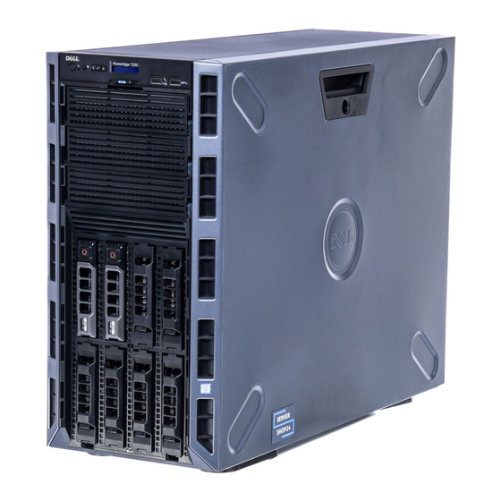
About the Dell PowerEdge T330 system The Dell PowerEdge T330 system is a rackable tower server that supports one processor based on the Intel E5-1200 v5 processor family, up to four DIMMs, and storage capacity of up to eight hard drives/solid state drives. -
Page 10: Front Panel Features And Indicators - Tower Mode
Front panel features and indicators — tower mode Figure 1. Front panel features and indicators — eight 3.5-inch hot swappable hard drive chassis... - Page 11 Displays system ID, status information, and system error messages. See LCD panel features. USB management port/ Functions as a regular USB port or provides access iDRAC Direct port to the iDRAC Direct features. For more information, see the iDRAC Guide at Dell.com/ idracmanuals.
- Page 12 Item Indicator, button, or Icon Description connector This port is USB 2.0-compliant USB connector Enables you to connect USB devices to the system. This port is USB 3.0-compliant. Optical drive or tape Enables you to install an optical drive or tape drives drives.
- Page 13 Figure 2. Front panel features and indicators — four 3.5-inch hot swappable hard drive chassis Table 3. Front panel features and indicators — four 3.5-inch hot swappable hard drive chassis Item Indicator, button, or Icon Description connector Power-on indicator, Enables you to know the power status of the power button system.
- Page 14 USB management port/ Functions as a regular USB port or provides access iDRAC Direct port to the iDRAC Direct features. For more information, see the iDRAC Guide at Dell.com/ idracmanuals. This port is USB 2.0-compliant USB connector Enables you to connect USB devices to the system.
-
Page 15: Front Panel Features And Indicators - Rack Mode
Item Indicator, button, or Icon Description connector Optical drive or tape Enables you to install an optical drive or tape drives drives. For more information about supported optical drives and tape drives, see Optical drives and tape drives (optional). Hard drives Enables you to install up to four 3.5-inch (2.5-inch with adapter) hot swappable hard drives/SSDs. - Page 16 USB management port/ Functions as a regular USB port or provides access iDRAC Direct port to the iDRAC Direct features. For more information, see the iDRAC Guide at Dell.com/ idracmanuals. This port is USB 2.0-compliant Video connector Enables you to connect a display to the system.
-
Page 17: Lcd Panel Features
The system's LCD panel provides system information and status and error messages to indicate if the system is operating correctly or if the system needs attention. For more information about the error messages, see the Dell Event and Error Messages Reference Guide at Dell.com/openmanagemanuals > OpenManage software. -
Page 18: Home Screen
SEL. This is useful when trying to match an LCD message with an SEL entry. Select Simple to view LCD error messages in a simplified user-friendly description. For more information about error messages, see the Dell Event and Error Messages Reference Guide at Dell.com/openmanagemanuals > OpenManage software. Set home Select the default information to be displayed on the Home screen. -
Page 19: View Menu
For more standby, and if any error information about error messages, see the exists (for example, a failed Dell Event and Error Messages Reference fan or hard drive). Guide at Dell.com/openmanagemanuals > OpenManage software. Invalid memory configurations can cause the system to halt at startup without any video output. - Page 20 Icon Description Condition Corrective action Electrical The indicator flashes amber Check the System Event Log or system indicator if the system experiences an messages for the specific issue. If it is due electrical error (for example, to a problem with the PSU, check the LED voltage out of range, or a on the PSU.
-
Page 21: Hot Swappable Hard Drive Indicator Codes
Hot swappable hard drive indicator codes Figure 5. Hot swappable hard drive indicators hard drive activity indicator hard drive status indicator hard drive NOTE: If the hard drive is in Advanced Host Controller Interface (AHCI) mode, the status indicator (on the right side) does not function and remains OFF. Table 6. -
Page 22: Back Panel Features And Indicators
Back panel features and indicators Figure 6. Back panel features and indicators Table 7. Back panel features and indicators Item Indicator, button, or Icon Description connector Power supply units (PSU1 Enables you to install up to two 495 W redundant and PSU2) and 350 W non-redundant AC power supply units. - Page 23 Item Indicator, button, or Icon Description connector NOTE: Non-redundant PSU is supported in systems with an x8 backplane. 2, 3 USB connectors (6) Enables you to connect USB devices to the system. Four ports are USB 2.0-compliant and two ports are USB 3.0-compliant. 4, 5 Ethernet connectors (2) Enable you to connect two integrated...
-
Page 24: Nic Indicator Codes
NIC indicator codes Figure 7. NIC indicators link indicator activity indicator Table 8. NIC indicators Convention Indicator pattern Description Link and activity indicators The NIC is not connected to the network. are OFF Link indicator is green The NIC is connected to a valid network at its maximum port speed (1 Gbps). - Page 25 CAUTION: Do not disconnect the power cord or unplug the PSU when updating firmware. If firmware update is interrupted, the PSUs will not function. You must roll back the PSU firmware by using Dell Lifecycle Controller. See Dell Lifecycle Controller User’s Guide at Dell.com/idracmanuals. Flashes green...
-
Page 26: Indicator Codes For Non-Redundant Power Supply Unit
Convention Power Indicator Description Pattern CAUTION: When correcting a PSU mismatch, replace only the PSU with the flashing indicator. Swapping the other PSU to make a matched pair can result in an error condition and unexpected system shutdown. To change from a High Output configuration to a Low Output configuration or vice versa, you must power down the system. -
Page 27: Documentation Matrix
Dell.com/poweredgemanuals. specifications Install the operating system Operating system documentation at Dell.com/ operatingsystemmanuals Get an overview of the Dell Systems Management Dell OpenManage Systems Management Overview offerings Guide at Dell.com/openmanagemanuals > OpenManage software Configure and log in to iDRAC, set up managed... -
Page 28: Accessing System Information By Using Qrl
Your system service tag to quickly access your specific hardware configuration and warranty information • A direct link to Dell to contact technical support and sales teams Steps Go to Dell.com/QRL and navigate to your specific product or Use your smartphone or tablet to scan the model-specific Quick Resource (QR) code located in the... -
Page 29: Performing Initial System Configuration
Turn on the system by pressing the power button or using iDRAC. Turn on the attached peripherals. Setting up and configuring the iDRAC IP address You can set up the Integrated Dell Remote Access Controller (iDRAC) IP address by using one of the following interfaces: •... -
Page 30: Logging In To Idrac
For more information about setting up and configuring iDRAC, see the Integrated Dell Remote Access Controller User's Guide at Dell.com/idracmanuals. Logging in to iDRAC You can log in to iDRAC as an iDRAC local user, a Microsoft Active Directory user, or a Lightweight Directory Access Protocol (LDAP) user. - Page 31 Steps Go to Dell.com/support/drivers. In the Product Selection section, enter the Service Tag of your system in the Service Tag or Express Service Code field. NOTE: If you do not have the Service Tag, select Automatically detect my Service Tag for me to enable the system to automatically detect your service tag, or select your product from the Product Selection page.
-
Page 32: Pre-Operating System Management Applications
Your system has the following pre-operating system management applications: • System Setup • Boot Manager • Dell Lifecycle Controller • Preboot Execution Environment (PXE) Navigation keys The navigation keys can help you quickly access the pre-operating system management applications. Description Enables you to enter System Setup. -
Page 33: About System Setup
UEFI. You can enable or disable various iDRAC parameters by using the iDRAC settings utility. For more information about this utility, see Integrated Dell Remote Access Controller User’s Guide at Dell.com/idracmanuals. Device Settings Enables you to configure device settings. -
Page 34: System Information Screen Details
Option Description Processor Settings Displays information and options related to the processor such as speed, cache size. SATA Settings Displays options to enable or disable the integrated SATA controller and ports. Boot Settings Displays options to specify the boot mode (BIOS or UEFI). Enables you to modify UEFI and BIOS boot settings. -
Page 35: Memory Settings Screen Details
Option Description UEFI Compliance Displays the UEFI compliance level of the system firmware. Version Memory Settings screen details You can use the Memory Settings screen to view all the memory settings and enable or disable specific memory functions, such as system memory testing and node interleaving. To view the Memory Setting screen, click System Setup Main Menu →... -
Page 36: Sata Settings Screen Details
NOTE: This option is only available on certain stock keeping units (SKUs) of the processors. X2Apic Mode Enables or disables the X2Apic mode. Dell Controlled Controls the turbo engagement. Enable this option only when System Profile is set Turbo to Performance. - Page 37 Option Description Write Cache Enables or disables the command for Embedded SATA drives during POST. Port A For AHCI or RAID mode, BIOS support is always enabled. Option Description Model Displays the drive model of the selected device. Drive Type Displays the type of drive attached to the SATA port.
-
Page 38: Boot Settings Screen Details
Option Description Option Description Capacity Displays the total capacity of the hard drive. This field is undefined for removable media devices such as optical drives. Port F For AHCI or RAID mode, BIOS support is always enabled. Option Description Model Displays the drive model of the selected device. -
Page 39: Network Settings Screen Details
Network Settings screen details You can use the Network Settings screen to modify PXE device settings. The network settings option is available only in the UEFI boot mode. BIOS does not control network settings in the BIOS boot mode. For BIOS boot mode, the option ROM of the network controllers handles the network settings. -
Page 40: Serial Communication Screen Details
Option Description Internal USB Port Enables or disables the internal USB port. This option is set to Enabled by default. Integrated Enables or disables the integrated network card. Network Card 1 Embedded NIC1 NOTE: The Embedded NIC1 and NIC2 options are only available on systems and NIC2 that do not have Integrated Network Card 1. -
Page 41: System Profile Settings Screen Details
Option Description NOTE: Every time the system boots, the BIOS syncs the serial MUX setting saved in iDRAC. The serial MUX setting can independently be changed in iDRAC. Loading the BIOS default settings from within the BIOS setup utility may not always revert the serial MUX setting to the default setting of Serial Device 1. -
Page 42: System Security Settings Screen Details
Option Description Enables or disables the processor to switch to a minimum performance state when it is idle. This option is set to Enabled by default. C States Enables or disables the processor to operate in all available power states. This option is set to Enabled by default. - Page 43 Option Description TPM Security NOTE: The TPM menu is available only when the TPM module is installed. Enables you to control the reporting mode of the TPM. The TPM Security option is set to Off by default. You can only modify the TPM Status, TPM Activation, and Intel TXT fields if the TPM Status field is set to either On with Pre-boot Measurements or On without Pre-boot Measurements.
-
Page 44: Miscellaneous Settings Screen Details
Secure Boot Custom Policy Settings screen details Secure Boot Custom Policy Settings is displayed only when the Secure Boot Policy option is set to Custom. To view the Secure Boot Custom Policy Settings screen, click System Setup Main Menu → System BIOS →... -
Page 45: About Boot Manager
Launches System Utilities menu such as System Diagnostics and UEFI shell. About Dell Lifecycle Controller Dell Lifecycle Controller enables you to perform tasks such as configuring BIOS and hardware settings, deploying an operating system, updating drivers, changing RAID settings, and saving hardware profiles. -
Page 46: Choosing The System Boot Mode
NOTE: Operating systems must be UEFI-compatible to be installed from the UEFI boot mode. DOS and 32-bit operating systems do not support UEFI and can only be installed from the BIOS boot mode. NOTE: For the latest information about supported operating systems, go to Dell.com/ossupport. Creating a system or setup password Prerequisites •... -
Page 47: Using Your System Password To Secure Your System
Press Esc to return to the System BIOS screen. Press Esc again. A message prompts you to save the changes. NOTE: Password protection does not take effect until the system reboots. Using your system password to secure your system About this task If you have assigned a setup password, the system accepts your setup password as an alternate system password. -
Page 48: Operating With A Setup Password Enabled
Embedded system management The Dell Lifecycle Controller provides advanced embedded systems management throughout the server’s lifecycle. The Dell Lifecycle Controller can be started during the boot sequence and can function independently of the operating system. NOTE: Certain platform configurations may not support the full set of features provided by the Dell Lifecycle Controller. -
Page 49: Changing The Thermal Settings
Changing the thermal settings The iDRAC settings utility enables you to select and customize the thermal control settings for your system. Click iDRAC Settings → Thermal. Under SYSTEM THERMAL PROFILE → Thermal Profile, select one of the following options: • Default Thermal Profile Settings •... -
Page 50: Installing And Removing System Components
Damage due to servicing that is not authorized by Dell is not covered by your warranty. Read and follow the safety instructions that came with the product. -
Page 51: After Working Inside Your System
Place the system upright on its feet on a flat and stable surface. Install the optional bezel. If applicable, install the system into the rack. For more information, see the Rack installation placemat at Dell.com/poweredgemanuals. Reconnect the system to an electrical outlet and peripherals. Turn on the system and any attached peripherals. -
Page 52: Removing The Optional Front Bezel
Figure 10. Installing and removing the optional front bezel release latch system bezel key slot on the chassis (2) bezel tab (2) bezel Removing the optional front bezel Unlock the bezel using the bezel keys. Press the release latch at the top of the bezel. Pull the top end of the bezel away from the system. -
Page 53: Installing The System Feet
Turn the system feet inward. Place the system on its side on a flat and stable surface. Steps Remove the screws securing the system feet to the base of the tower. Figure 11. Removing and installing the system feet screw hole (4) slot (12) tab (12) base of the tower... -
Page 54: Caster Wheels (Optional)-Tower Mode
Steps Align the tabs on the system feet with the slots on the base of the chassis. Secure the system feet to the base of the chassis by using the screws. Next steps Place the system upright on a flat and stable surface, and turn the system feet outward. Related Tasks Removing the system feet Caster wheels (optional)—tower mode... -
Page 55: Removing Caster Wheels
Figure 12. Removing and installing caster wheels support unit screw for support unit (2) slot on base of the tower (4) wheel assembly unit (2) screw for wheel assembly (2) Related Tasks Removing the system feet Removing caster wheels Removing caster wheels Prerequisites Ensure that you follow the Safety... -
Page 56: System Cover
Related Tasks Installing caster wheels System cover Removing the system cover Prerequisites Ensure that you follow the Safety instructions. Turn off the system and any attached peripherals. Disconnect the system from the electrical outlet and peripherals. If installed, remove the front bezel. Place the system on a flat and stable surface. -
Page 57: Installing The System Cover
Installing the system cover Installing the system cover Prerequisites Ensure that you follow the Safety instructions. Steps Align the slots on the system cover with the tabs on the chassis. Press the cover release latch, and push the cover toward the chassis until the latch locks into place. Turn the cover release latch lock to the locked position. -
Page 58: Inside The System
Systems with hot swappable hard drives support up to one optical drive and two tape drives. NOTE: You can also install a Dell PowerVault RD1000 removable media device on your system. For systems with hot swappable hard drives, the optical and tape drives can be configured as follows:... -
Page 59: Removing The Optional Optical Drive Or Tape Drive
Damage due to servicing that is not authorized by Dell is not covered by your warranty. Read and follow the safety instructions that came with the product. - Page 60 Figure 15. Removing and installing the optional optical drive or tape drive optical drive or tape drive guide release latch...
- Page 61 Figure 16. Cabling— optical drive and tape drive PERC card system board optical disk drive connector on the SATA tape drive connector on the system board system board SAS tape drive optical disk drive or SATA tape drive optical disk drive SAS tape drive connector on the PERC card Next steps...
-
Page 62: Installing The Optical Drive Or Tape Drive
Damage due to servicing that is not authorized by Dell is not covered by your warranty. Read and follow the safety instructions that came with the product. -
Page 63: Installing The Cooling Shroud
Damage due to servicing that is not authorized by Dell is not covered by your warranty. Read and follow the safety instructions that came with the product. -
Page 64: Intrusion Switch
Damage due to servicing that is not authorized by Dell is not covered by your warranty. Read and follow the safety instructions that came with the product. -
Page 65: Installing The Intrusion Switch
Damage due to servicing that is not authorized by Dell is not covered by your warranty. Read and follow the safety instructions that came with the product. -
Page 66: Hard Drives
For more information about these hard drives, see the 512e and 4Kn Disk Formats whitepaper and 4K Sector HDD FAQ document at Dell.com/poweredgemanuals. CAUTION: Before attempting to remove or install a hard drive while the system is running, see the documentation for the storage controller card to ensure that the host adapter is configured correctly to support hot swappable hard drive removal and insertion. -
Page 67: Removing A 3.5-Inch Hot Swappable Hard Drive Carrier Blank
Damage due to servicing that is not authorized by Dell is not covered by your warranty. Read and follow the safety instructions that came with the product. -
Page 68: Removing A Hot Swappable Hard Drive Carrier
Damage due to servicing that is not authorized by Dell is not covered by your warranty. Read and follow the safety instructions that came with the product. -
Page 69: Removing A Hot Swappable Hard Drive From A Hard Drive Carrier
Damage due to servicing that is not authorized by Dell is not covered by your warranty. Read and follow the safety instructions that came with the product. -
Page 70: Installing A Hot Swappable Hard Drive Into A Hot Swappable Hard Drive Carrier
Damage due to servicing that is not authorized by Dell is not covered by your warranty. Read and follow the safety instructions that came with the product. -
Page 71: Installing A Hot Swappable Hard Drive Carrier
Damage due to servicing that is not authorized by Dell is not covered by your warranty. Read and follow the safety instructions that came with the product. -
Page 72: Installing A 2.5-Inch Hot Swappable Hard Drive Into A 3.5-Inch Hard Drive Adapter
Damage due to servicing that is not authorized by Dell is not covered by your warranty. Read and follow the safety instructions that came with the product. -
Page 73: Installing A 3.5-Inch Hard Drive Adapter Into The 3.5-Inch Hot Swappable Hard Drive Carrier
Damage due to servicing that is not authorized by Dell is not covered by your warranty. Read and follow the safety instructions that came with the product. -
Page 74: Removing A 3.5-Inch Hard Drive Adapter From A 3.5-Inch Hot Swappable Hard Drive Carrier
Damage due to servicing that is not authorized by Dell is not covered by your warranty. Read and follow the safety instructions that came with the product. -
Page 75: Removing The Hard Drive Backplane
Damage due to servicing that is not authorized by Dell is not covered by your warranty. Read and follow the safety instructions that came with the product. - Page 76 optical disk drive power cable release pin signal cable Figure 25. Connectors on an x8 hard drive backplane x8 hard drive backplane optical disk drive connector backplane power connector backplane signal connector SAS A connector SAS B connector...
- Page 77 Figure 26. Cabling—x8 hard drive backplane with PERC card and SAS HBA PERC card SAS tape drive connector on SAS HBA SAS Host Bus Adapter (HBA) system board optical disk drive connector on system SATA connector on system board board x8 hard drive backplane SAS B connector on backplane SAS A connector on backplane...
- Page 78 Figure 27. Cabling—x4 hard drive backplane system board SATA connector on system board optical disk drive connector on system mini SAS connector board x4 hard drive backplane SAS A connector on backplane optical disk drive or SATA tape drive optical disk drive Next steps Install the hard drive backplane.
-
Page 79: Installing The Hard Drive Backplane
Damage due to servicing that is not authorized by Dell is not covered by your warranty. Read and follow the safety instructions that came with the product. -
Page 80: Installing A Four-Slot Hard Drive Blank
Steps Using a screwdriver, push the release tabs on the corners of the blank from inside the system, to unlock the four-slot hard drive blank from the chassis. From the front of the system, pull the four-slot hard drive blank at the corners until it is free of the hard drive slot. -
Page 81: System Memory
Steps Locate the hard drive slots numbered from four to seven. Insert the four-slot hard drive blank into the hard drive slot, and push it until the release tabs click into place. Next steps Install the x8 hard drive backplane. Install all hard drives. -
Page 82: General Memory Module Installation Guidelines
Figure 29. Memory socket locations on the system board Memory channels are organized as follows: Processor 1 channel 0: memory sockets A1 and A3 channel 1: memory sockets A2 and A4 The following table shows the memory populations and operating frequencies for the supported configurations: Table 12. -
Page 83: Sample Memory Configurations
• Populate all sockets with white release levers first, and then all the sockets with black release levers. • When mixing memory modules with different capacities, populate the sockets with memory modules with the highest capacity first. For example, if you want to mix 4 GB and 8 GB DIMMs, populate 8 GB DIMMs in the sockets with white release levers and 4 GB DIMMs in the sockets with black release levers. -
Page 84: Removing Memory Modules
Damage due to servicing that is not authorized by Dell is not covered by your warranty. Read and follow the safety instructions that came with the product. -
Page 85: Installing Memory Modules
Damage due to servicing that is not authorized by Dell is not covered by your warranty. Read and follow the safety instructions that came with the product. -
Page 86: Cooling Fans
Installing the cooling shroud Cooling fans The system supports an internal cooling fan. NOTE: When selecting or upgrading your system configuration, verify the system power consumption with the Dell Energy Smart Solution Advisor at Dell.com/ESSA to ensure optimum power utilization. -
Page 87: Removing The Internal Cooling Fan
Damage due to servicing that is not authorized by Dell is not covered by your warranty. Read and follow the safety instructions that came with the product. -
Page 88: Installing The Internal Cooling Fan
Damage due to servicing that is not authorized by Dell is not covered by your warranty. Read and follow the safety instructions that came with the product. -
Page 89: Internal Usb Memory Key (Optional)
Damage due to servicing that is not authorized by Dell is not covered by your warranty. Read and follow the safety instructions that came with the product. -
Page 90: Expansion Cards
Figure 33. Replacing the internal USB memory key USB memory key USB memory key connector Next steps Follow the procedure listed in After working inside your system. While booting, press F2 to enter System Setup and verify that the USB memory key is detected by the system. -
Page 91: Removing An Expansion Card
Damage due to servicing that is not authorized by Dell is not covered by your warranty. Read and follow the safety instructions that came with the product. - Page 92 Steps Open the expansion card latch by pulling the latch up. Hold the expansion card by its edges, and pull the card until the card edge connector disengages from the expansion card connector. Install the filler bracket by performing the following steps: a.
-
Page 93: Installing An Expansion Card
Damage due to servicing that is not authorized by Dell is not covered by your warranty. Read and follow the safety instructions that came with the product. -
Page 94: Idrac Port Card (Optional)
Damage due to servicing that is not authorized by Dell is not covered by your warranty. Read and follow the safety instructions that came with the product. - Page 95 Steps Loosen the screw that secures the iDRAC port card holder to the system board. Pull the iDRAC port card to disengage it from the iDRAC port card connector on the system board, and remove the card from the chassis. Figure 36.
-
Page 96: Installing The Optional Idrac Port Card
Damage due to servicing that is not authorized by Dell is not covered by your warranty. Read and follow the safety instructions that came with the product. -
Page 97: Internal Dual Sd Module (Optional)
Damage due to servicing that is not authorized by Dell is not covered by your warranty. Read and follow the safety instructions that came with the product. -
Page 98: Installing An Optional Internal Sd Card
Damage due to servicing that is not authorized by Dell is not covered by your warranty. Read and follow the safety instructions that came with the product. - Page 99 Figure 38. Removing and installing the Internal Dual SD Module (IDSDM) IDSDM LED status indicator (2) SD card (2) SD card slot 2 SD card slot 1 IDSDM connector The following table describes the IDSDM indicator codes: Table 16. IDSDM indicator codes Convention IDSDM indicator code Condition...
-
Page 100: Installing The Optional Internal Dual Sd Module
Damage due to servicing that is not authorized by Dell is not covered by your warranty. Read and follow the safety instructions that came with the product. -
Page 101: Removing The Heat Sink
Damage due to servicing that is not authorized by Dell is not covered by your warranty. Read and follow the safety instructions that came with the product. -
Page 102: Removing The Processor
Damage due to servicing that is not authorized by Dell is not covered by your warranty. Read and follow the safety instructions that came with the product. - Page 103 If you are upgrading your system, download the latest system BIOS version from Dell.com/support and follow the instructions included in the compressed download file to install the update on your system. NOTE: You can update the system BIOS by using the Dell Lifecycle Controller.
- Page 104 Figure 40. Opening and closing the processor shield processor shield tab on the processor shield socket lever...
-
Page 105: Installing The Processor
Damage due to servicing that is not authorized by Dell is not covered by your warranty. Read and follow the safety instructions that came with the product. - Page 106 Ensure that you follow the Safety instructions. If you are upgrading your system, download the latest system BIOS version from Dell.com/support and follow the instructions included in the compressed download file to install the update on your system. NOTE: You can update the system BIOS by using the Dell Lifecycle Controller.
-
Page 107: Installing The Heat Sink
Damage due to servicing that is not authorized by Dell is not covered by your warranty. Read and follow the safety instructions that came with the product. - Page 108 Figure 42. Applying thermal grease on the top of the processor processor thermal grease thermal grease syringe Place the heat sink onto the processor. Tighten one of the four screws to secure the heat sink to the system board. Tighten the screw diagonally opposite to the first screw you tightened. NOTE: Do not overtighten the heat sink retention screws when installing the heat sink.
-
Page 109: Power Supply Units
Damage due to servicing that is not authorized by Dell is not covered by your warranty. Read and follow the safety instructions that came with the product. - Page 110 Damage due to servicing that is not authorized by Dell is not covered by your warranty. Read and follow the safety instructions that came with the product.
- Page 111 Verify that both the power supply units (PSUs) are the same type and have the same maximum output power. NOTE: The maximum output power (shown in watts) is listed on the PSU label. If installed, remove the PSU blank. Steps Slide the new PSU into the chassis until the PSU is fully seated and the release latch snaps into place.
- Page 112 Damage due to servicing that is not authorized by Dell is not covered by your warranty. Read and follow the safety instructions that came with the product.
- Page 113 Steps Remove the screw that secures the PSU divider to the chassis. Slide out the PSU divider and turn it clockwise to free the tabs on the PSU divider from the slots on the PSU cage. Slide the PSU divider out of the chassis. Align the tabs of the new PSU divider with the slots of the PSU cage.
-
Page 114: Non-Redundant Ac Power Supply Unit
Damage due to servicing that is not authorized by Dell is not covered by your warranty. Read and follow the safety instructions that came with the product. - Page 115 Figure 46. Removing and installing a non-redundant AC PSU screw PSU cage non-redundant PSU standoff on the chassis P2 power cable connector P1 signal cable connector P1 power cable connector P4/backplane connector Next steps Install a non-redundant PSU. Follow the procedure listed in After working inside your system.
-
Page 116: Power Interposer Board
Damage due to servicing that is not authorized by Dell is not covered by your warranty. Read and follow the safety instructions that came with the product. -
Page 117: Installing The Power Interposer Board
Damage due to servicing that is not authorized by Dell is not covered by your warranty. Read and follow the safety instructions that came with the product. -
Page 118: System Battery
Damage due to servicing that is not authorized by Dell is not covered by your warranty. Read and follow the safety instructions that came with the product. - Page 119 Figure 48. Removing the system battery plastic scribe positive side of the battery connector securing tabs Install a new system battery by holding the battery with the "+" sign facing up and slide it under the securing tabs. Press the battery into the connector until it snaps into place. Figure 49.
-
Page 120: Control Panel Assembly
Damage due to servicing that is not authorized by Dell is not covered by your warranty. Read and follow the safety instructions that came with the product. - Page 121 Figure 50. Removing and installing the control panel assembly control panel control panel cable control panel USB cable screw Locate and press the tabs on the information tag. Push the information tag out of the slot to remove it from the control panel. NOTE: Retain the information tag to replace it in the new control panel.
-
Page 122: Installing The Control Panel Assembly
Damage due to servicing that is not authorized by Dell is not covered by your warranty. Read and follow the safety instructions that came with the product. -
Page 123: Removing The Control Panel Assembly Cover
Damage due to servicing that is not authorized by Dell is not covered by your warranty. Read and follow the safety instructions that came with the product. -
Page 124: Installing The Control Panel Assembly Cover
Damage due to servicing that is not authorized by Dell is not covered by your warranty. Read and follow the safety instructions that came with the product. -
Page 125: Removing The Control Panel Board
Damage due to servicing that is not authorized by Dell is not covered by your warranty. Read and follow the safety instructions that came with the product. -
Page 126: Installing The Control Panel Board
Damage due to servicing that is not authorized by Dell is not covered by your warranty. Read and follow the safety instructions that came with the product. -
Page 127: Removing The Lcd Module
Damage due to servicing that is not authorized by Dell is not covered by your warranty. Read and follow the safety instructions that came with the product. -
Page 128: Installing The Lcd Module
Damage due to servicing that is not authorized by Dell is not covered by your warranty. Read and follow the safety instructions that came with the product. -
Page 129: Removing The Optional Vga Module
Damage due to servicing that is not authorized by Dell is not covered by your warranty. Read and follow the safety instructions that came with the product. -
Page 130: Installing The Optional Vga Module
Damage due to servicing that is not authorized by Dell is not covered by your warranty. Read and follow the safety instructions that came with the product. - Page 131 CAUTION: If you are using the Trusted Program Module (TPM) with an encryption key, you may be prompted to create a recovery key during program or System Setup. Be sure to create and safely store this recovery key. If you replace this system board, you must supply the recovery key when you restart your system or program before you can access the encrypted data on your hard drives.
- Page 132 Figure 56. Removing and installing the screws on the system board screw (8)
- Page 133 Figure 57. Removing and installing the system board system board touch point (2) system board t-handle post Next steps Install the system board. Follow the procedure listed in After working inside your system. Related Tasks Removing the cooling shroud Removing memory modules Removing the internal cooling fan Removing an expansion card Removing the heat sink...
-
Page 134: Installing The System Board
Damage due to servicing that is not authorized by Dell is not covered by your warranty. Read and follow the safety instructions that came with the product. -
Page 135: Restoring The Service Tag By Using The Easy Restore Feature
• Press Y to restore the Service Tag, license, and diagnostics information. • Press N to navigate to the Dell Lifecycle Controller based restore options. • Press F10 to restore data from a previously created Hardware Server Profile. After the restore process is complete, BIOS prompts to restore the system configuration data. -
Page 136: Trusted Platform Module
Damage due to servicing that is not authorized by Dell is not covered by your warranty. Read and follow the safety instructions that came with the product. -
Page 137: Re-Enabling The Tpm For Bitlocker Users
Figure 58. Installing the TPM TPM connector slot on the TPM connector plastic bolt slot on the system board Next steps Install the system board. Follow the procedure listed in After working inside your system. Related Tasks Installing the system board Re-enabling the TPM for BitLocker users Initialize the TPM. -
Page 138: System Top Cover
Damage due to servicing that is not authorized by Dell is not covered by your warranty. Read and follow the safety instructions that came with the product. -
Page 139: Installing The System Top Cover
Damage due to servicing that is not authorized by Dell is not covered by your warranty. Read and follow the safety instructions that came with the product. - Page 140 Next steps Install the system cover. Reconnect the system to its electrical outlet and turn the system on, including any attached peripherals.
-
Page 141: Converting The System From Tower Mode To Rack Mode
CAUTION: Do not attempt to convert your system into a rack unless authorized by Dell. Only customers certified by Dell for tower to rack conversion can convert a tower system into a rack system. NOTE: For specific caution statements and procedures, see the rack installation documentation for your system at Dell.com/poweredgemanuals. - Page 142 Figure 60. Removing and installing the rack ears 1. front panel 2. rack ear (2) 3. screw for each rack ear (3) Next steps Install the system cover. Install the system in a rack. For more information, see the system’s Rack Installation Guide at Dell.com/poweredgemanuals.
- Page 143 Related Tasks Removing the system feet Removing caster wheels Removing the system cover Removing the control panel assembly Removing the control panel assembly cover Installing the optional VGA module Installing the control panel assembly cover Removing the system top cover Installing the control panel assembly...
-
Page 144: Troubleshooting Your System
Damage due to servicing that is not authorized by Dell is not covered by your warranty. Read and follow the safety instructions that came with the product. -
Page 145: Troubleshooting Idrac Direct (Usb Xml Configuration)
Getting Help. Troubleshooting iDRAC Direct (USB XML configuration) For information on USB storage device and server configuration, see the Integrated Dell Remote Access Controller User's Guide at Dell.com/esmmanuals. Steps Ensure that your USB storage device is connected to the front USB Management Port, identified by icon. -
Page 146: Troubleshooting Idrac Direct (Laptop Connection)
Getting help. Troubleshooting iDRAC Direct (Laptop connection) For information on USB laptop connection and server configuration, see the Integrated Dell Remote Access Controller User's Guide at Dell.com/esmmanuals. Steps Ensure that your laptop is connected to the front USB Management Port, identified by icon with a USB Type A/A cable. -
Page 147: Troubleshooting A Wet System
Damage due to servicing that is not authorized by Dell is not covered by your warranty. Read and follow the safety instructions that came with the product. -
Page 148: Troubleshooting A Damaged System
Damage due to servicing that is not authorized by Dell is not covered by your warranty. Read and follow the safety instructions that came with the product. -
Page 149: Troubleshooting Power Supply Units
Damage due to servicing that is not authorized by Dell is not covered by your warranty. Read and follow the safety instructions that came with the product. -
Page 150: Troubleshooting Cooling Problems
Damage due to servicing that is not authorized by Dell is not covered by your warranty. Read and follow the safety instructions that came with the product. -
Page 151: Troubleshooting System Memory
Damage due to servicing that is not authorized by Dell is not covered by your warranty. Read and follow the safety instructions that came with the product. -
Page 152: Troubleshooting An Internal Usb Key
Damage due to servicing that is not authorized by Dell is not covered by your warranty. Read and follow the safety instructions that came with the product. -
Page 153: Troubleshooting An Optical Drive
Damage due to servicing that is not authorized by Dell is not covered by your warranty. Read and follow the safety instructions that came with the product. -
Page 154: Troubleshooting A Hard Drive
If your system has a RAID controller and your hard drives are configured in a RAID array, perform the following steps: a. Restart the system and press F10 during system startup to run the Dell Lifecycle Controller, and then run the Hardware Configuration wizard to check the RAID configuration. -
Page 155: Troubleshooting A Storage Controller
Damage due to servicing that is not authorized by Dell is not covered by your warranty. Read and follow the safety instructions that came with the product. -
Page 156: Troubleshooting Processors
Damage due to servicing that is not authorized by Dell is not covered by your warranty. Read and follow the safety instructions that came with the product. -
Page 157: Using System Diagnostics
Using system diagnostics If you experience a problem with your system, run the system diagnostics before contacting Dell for technical assistance. The purpose of running system diagnostics is to test your system hardware without requiring additional equipment or risking data loss. If you are unable to fix the problem yourself, service and support personnel can use the diagnostics results to help you solve the problem. -
Page 158: System Diagnostics Controls
System diagnostics controls Menu Description Configuration Displays the configuration and status of all detected devices. Results Displays the results of all tests that are executed. System health Provides the current overview of the system performance. Event log Displays a time-stamped log of the results of all tests run on the system. This is displayed if at least one event description is recorded. -
Page 159: Jumpers And Connectors
Jumpers and connectors System board jumpers and connectors Figure 61. System board jumpers and connectors Table 17. System board jumpers and connectors Connector Description Slot 1 PCIE_G3_X4 PCIe card connector 1 Slot 2 PCIE_G3_X8 PCIe card connector 2... -
Page 160: System Board Jumper Settings
Damage due to servicing that is not authorized by Dell is not covered by your warranty. Read and follow the safety instructions that came with the product. -
Page 161: Disabling A Forgotten Password
Damage due to servicing that is not authorized by Dell is not covered by your warranty. Read and follow the safety instructions that came with the product. -
Page 162: Technical Specifications
Technical specifications Dimensions and weight Physical Dimensions Height 443.3 mm (17.45 inch) with feet 430.3 mm (16.94 inch) without feet Width 304.5 mm (11.98 inch) with feet opened 218 mm (8.58 inch) with feet closed Depth 561.8 mm (22.12 inch) without bezel 578.2 mm (22.76 inch) with bezel Weight (maximum) 26.02 kg (57.32 lb) Processor specifications... -
Page 163: Power Specifications
Storage controller Specification Storage controller PERC H730, PERC H330, PERC H830, PERC S130. type NOTE: Your system supports software RAID S130 and a PERC card. For more information on software RAID, see the Dell PowerEdge RAID Controller (PERC) documentation at Dell.com/storagecontrollermanuals. -
Page 164: Drive Specifications
Drive specifications Drives Specification Eight hard drive Up to eight 3.5-inch hot swappable SATA, or nearline SAS hard drives systems NOTE: 2.5-inch hard drives in 3.5-inch carriers are supported for SAS, and SATA SSD hard drives Four hard drive Up to four 3.5-inch hot swappable SATA, or nearline SAS hard drives systems NOTE: 2.5-inch hard drives in 3.5-inch carriers are supported for SAS, and SATA SSD hard drives... -
Page 165: Video Specifications
Non-redundant power supply units are not supported. Restrictions • Cabled power supply units are not supported. • Non Dell qualified peripheral cards and/or peripheral cards greater than 25 W are not supported. • Internal Tape backup drive (TBU) is not supported. •... -
Page 166: Environmental Specifications
Environmental specifications NOTE: For additional information about environmental measurements for specific system configurations, see Dell.com/environmental_datasheets. Temperature Specifications Storage –40°C to 65°C (–40°F to 149°F) Continuous 10°C to 35°C (50°F to 95°F) with no direct sunlight on the equipment. operation (for... - Page 167 Operating Specifications temperature de- rating 35 °C to 40 °C (95 Maximum temperature is reduced by 1°C/175 m (1°F/319 ft) above 950 m (3,117 ft). °F to 104 °F) 40 °C to 45 °C Maximum temperature is reduced by 1°C/125 m (1°F/228 ft) above 950 m (3,117 ft). (104 °F to 113 °F) The following section defines the limits to help avoid IT equipment damage and/or failure from particulates and gaseous contamination.
-
Page 168: Getting Help
Getting help Contacting Dell Dell provides several online and telephone-based support and service options. If you do not have an active internet connection, you can find contact information on your purchase invoice, packing slip, bill, or Dell product catalog. Availability varies by country and product, and some services may not be available in your area. - Page 169 Your system service tag to quickly access your specific hardware configuration and warranty information • A direct link to Dell to contact technical support and sales teams Steps Go to Dell.com/QRL and navigate to your specific product or Use your smartphone or tablet to scan the model-specific Quick Resource (QR) code located in the...