
Related Manuals for Brother bas-311hn


Summary of Contents for Brother bas-311hn
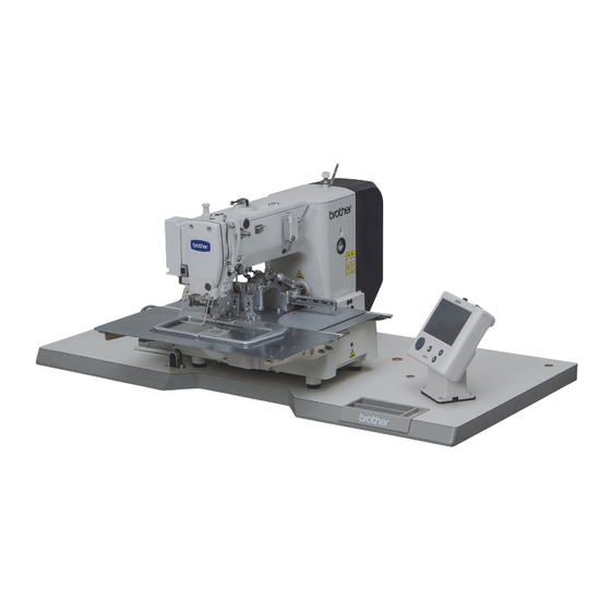
- Page 1 BAS-311HN INSTRUCTION MANUAL INSTRUCTION MANUAL BAS-326H Please read this manual before using the machine. Please keep this manual within easy reach for quick reference. DIRECT DRIVE PROGRAMMABLE ELECTRONIC PATTERN SEWER...
- Page 2 Thank you very much for buying a BROTHER sewing machine. Before using your new machine, please read the safety instructions below and the explanations given in the instruction manual. With industrial sewing machines, it is normal to carry out work while positioned directly in front of moving parts such as the needle and thread take-up lever, and consequently there is always a danger of injury that can be caused by these parts.
-
Page 3: Safety Instructions
This symbol ( ) indicates something that you must do. The picture inside the circle indicates the ・・・・・・ nature of the thing that must be done. (For example, the symbol at left means “you must make the ground connection”.) BAS-311HN, BAS-326H... - Page 4 Furthermore, do not excessively bend the cords or secure them too firmly Contact your Brother dealer or a qualified electrician with staples, otherwise there is the danger that fire or for any electrical work that may need to be done.
-
Page 5: Maintenance And Inspection
Furthermore, do not apply excessive force when Ask your Brother dealer or a qualified electrician to tilting back the machine head. The sewing machine carry out any maintenance and inspection of the may become unbalanced and fall down, and serious electrical system. - Page 6 The following warning labels appear on the sewing machine. Please follow the instructions on the labels at all times when using the machine. If the labels have been removed or are difficult to read, please contact your nearest Brother dealer. *Safety devices...
- Page 7 Thread take-up cover Thread take-up cover Eye guard Eye guard Finger guard Finger guard Inner cover R Inner cover R Outer cover Outer cover Fixed cover Fixed cover Gas spring support cover Gas spring support cover 3504B 3505B BAS-311HN, BAS-326H...
-
Page 8: Table Of Contents
6-6. Lubrication............34 3-4. Installing the machine head......5 6-7. Applying grease 3-5. Installing the LCD panel ........8 (Feed mechanism BAS-311HN) .......35 3-6. Installing the two-pedal foot switch ....9 7. STANDARD ADJUSTMENTS ....3-7. Connecting the cords........9 7-1. Checking the machine head switch ....37 3-8. -
Page 9: Names Of Major Parts
(3) LCD panel (12) Eye guard (4) Foot switch (13) Thread take-up cover (5) Work clamp switch (14) Rear cover (6) Start switch (7) STOP switch (8) Pulley (9) Cotton stand (10) Solenoid valve (pneumatic work clamp specifications) BAS-311HN, BAS-326H... -
Page 10: Specifications
Lock stitch pattern tacking sewing machine Stitch formation Single needle lock stitch Max. sewing speed 2,800 sti/min Max. sewing area (XxY) BAS-311HN: 150 x 100 mm BAS-326H: 220 x 100 mm Feed mechanism Intermittent feed, pulse motor drive 0.05 − 12.7 mm Stitch length Maximum No. -
Page 11: Installation
Furthermore, do not excessively bend the cords or secure them too firmly staples, Contact your Brother dealer or a qualified electrician otherwise there is the danger that fire or electric for any electrical work that may need to be done. -
Page 12: Installing The Control Box
(6) Spring washers [4 pcs.] (7) Nuts [8 pcs.] 3033B (8) Power switch (9) Wood screws [2 pcs.] (10) Staples [4 pcs.] Operator 1841B 3-3. Installing the oil pan (1) Oil pan (2) Nails [6 pcs.] (3) Waste oil tank 3034B BAS-311HN, BAS-326H... -
Page 13: Installing The Machine Head
Approx. 20 mm of the pulse motor. Approx. 20 mm 3506B (4) Hinge holders [2 pcs.] (5) Bolts [4 pcs.] (6) Plain washers [4 pcs.] (7) Nuts [4 pcs.] (8) Head rest (9) Bolts with washer [4 pcs.] 3230B BAS-311HN, BAS-326H... - Page 14 • Be careful not to clamp any items such as screwdrivers under the cushion when tilting back 3432B machine head. (12) Bobbin winder tension assembly (13) Set screw [1 pc.] 3521B BAS-311HN, BAS-326H...
- Page 15 (28) Gas spring shaft U (29) Retaining rings E [2 pcs.] (30) Plain washers (small) [2 pcs.] (31) Absorber setting plate (32) Bolts with washer [2 pcs.] 3534B (33) Gas spring support cover (34) Bolts with washer [6 pcs.] 3535B BAS-311HN, BAS-326H...
-
Page 16: Installing The Lcd Panel
(PANEL) connector (9) on the side of the control box. • Tighten the four wood screws (3) so that the thickness of the rubber cushion (2) is 5 mm. 3554B BAS-311HN, BAS-326H... -
Page 17: Installing The Two-Pedal Foot Switch
• Check that the connector is facing the correct way, and then insert it firmly until it locks into place. • Secure the cables with cable ties and cord clamps, while being careful not to pull on the connector. 3528B BAS-311HN, BAS-326H... - Page 18 Upper thread breakage detector [2-pin] White P36, P9(HEAD) (2) (3) NOTE: Route the X, Y and work clamp pulse motor harnesses so that they do not touch the power supply P.C. board at the bottom of the control box. BAS-311HN, BAS-326H...
- Page 19 Close the cord presser plate (6) securely so that no foreign objects, insects or small animals can get inside the control box. 6. Check that the cords do not get pulled, and then gently return the machine head to its original position. 3538B BAS-311HN, BAS-326H...
- Page 20 3. INSTALLATION <LCD panel> (PANEL) Connector D-sub connector LCD panel [9-pin] (PANEL) 3557B BAS-311HN, BAS-326H...
-
Page 21: Connecting The Ground Wire
(2) Ground wires from two-pedal foot switch harnesses (2 wires) • Tighten the control box cover with the six screws. Check that the cords are not clamped by the cover at this time. NOTE: Make sure that the ground connections are secure in order to ensure safety. BAS-311HN, BAS-326H... -
Page 22: Connecting The Power Cord
• Take care when tapping in the staples (3) to make sure that they do not pierce the cords. • Do not use extension cords, otherwise machine operation problems result. Control box Green and yellow wire (ground wire) 3665B BAS-311HN, BAS-326H... - Page 23 3. Use the six screws to tighten the cover of the control box. Check that none of the cords are being clamped by the cover at this time. Green and yellow wire (ground wire) BAS-311HN, BAS-326H...
- Page 24 3. Use the six screws to tighten the cover of the control box. Check that none of the cords are being clamped by the cover at this time. Green and yellow wire (ground wire) 3658B BAS-311HN, BAS-326H...
-
Page 25: Installing The Cotton Stand
3. INSTALLATION 3-10. Installing the cotton stand (1) Cotton stand NOTE: Securely tighten the nut (3) so that two washers (2) are securely clamped so that the cotton stand (1) does not move. 3640B BAS-311HN, BAS-326H... -
Page 26: Installing The Pneumatic Unit (Pneumatic Work Clamp Specifications)
• When the lower knob is tightened, the lowering speed becomes slower. When it is loosened, the lowering speed becomes faster. You can operate the work clamp while the power is turned off by pressing the manual button. 3235B 1905B BAS-311HN, BAS-326H... -
Page 27: Installing The Eye Guard
3-13. Installing the side cover and rear cover (1) Side cover 3509B (2) Screws [4 pcs.] (3) Rear cover (4) Screws [4 pcs.] NOTE: Be careful not to clamp the cords when installing the side cover and the rear cover. 3510B BAS-311HN, BAS-326H... -
Page 28: Lubrication
Use only the lubricating oil <JX Nippon Oil & Energy Corporation Sewing Lube N10; VG10> specified by Brother. * If this type of lubricating oil is difficult to obtain, the recommended oil to use is <Exxon Mobil Essotex SM10; VG10>. -
Page 29: Installing The Machine Head Fixing Bolt
<If error [E050], [E051] or [E055] is displayed> If the machine head switch (1) is not turned on, error [E050], [E051] or [E055] will occur. Use the screw (2) to adjust the installation position of the machine head switch as shown in the illustration. 3054B BAS-311HN, BAS-326H... -
Page 30: Preparation Before Sewing
1. Loosen the set screw (1). 2. Insert the needle (2) in a straight line as far as it will go, making sure that the long groove on the needle is at the front, and then securely tighten the set screw (1). 3057B BAS-311HN, BAS-326H... -
Page 31: Threading The Upper Thread
If it is too long, the thread may become tangled, and if it is too short, the thread may pull out at the sewing start. • If you would like to adjust the sensitivity of the thread breakage sensor, refer to "7-2. Adjusting the sensitivity of the thread breakage sensor". BAS-311HN, BAS-326H... -
Page 32: Threading Mode
• The tension discs will open. Threading the thread. Ending threading mode Touch the OK key on the screen. The display will return to the previous screen. • The work clamp will return to where it was before threading mode was started. BAS-311HN, BAS-326H... -
Page 33: Winding The Lower Thread
10. Remove the bobbin, hook the thread onto the knife (3), and then pull the bobbin in the direction of the arrow to cut the thread. 11. Touch the OK key (5) to return to the previous screen. 3550B BAS-311HN, BAS-326H... - Page 34 Loosen the set screw (8) and move the bobbin winder tension assembly (9) up and down to adjust. * For case A, move the bobbin winder tension assembly (9) down, and for case B, move it upward. Case A Case B 3684B BAS-311HN, BAS-326H...
-
Page 35: Installing The Bobbin Case
4. Check that the bobbin turns in the direction of the arrow when the thread is pulled. 5. Pass the thread through the lever thread hole (4), and then pull out approximately 30 mm of thread. 6. Hold the latch on the bobbin case and insert the bobbin case into the rotary hook. BAS-311HN, BAS-326H... -
Page 36: Thread Tension
Adjust the thread tension to the weakest possible tension by turning the thread tension nut (1) until the bobbin case will not drop by its own weight while the thread end coming out of the bobbin case is held. Stronger Weaker 2536Q BAS-311HN, BAS-326H... -
Page 37: Upper Thread Tension
1. Turn the tension nut (1) (main tension) to adjust the tension as appropriate for the material being sewn. 2. Use the tension nut (2) (sub-tension) to adjust so that the upper thread trailing length after thread trimming is about 42 mm. Stronger Weaker Stronger Weaker 3067B BAS-311HN, BAS-326H... -
Page 38: Starting Up
No programs are registered at the time of shipment from the factory, and so "---" is displayed as the program number (No.). For details on the sewing data reading method, refer to "3. USING STORAGE MEDIA" in the "LCD Panel/Operation Panel" Instruction Manual. BAS-311HN, BAS-326H... -
Page 39: Sewing
Use a work clamp which will hold the material securely so that it does not slip. If the material slips when using the standard work clamp and feed plate, process them so that the material does not slip. 3552B BAS-311HN, BAS-326H... -
Page 40: Using The Stop Switch
The sewing machine will start operating and sewing will start. 4441Q <Returning to the sewing start position without continuing sewing> If you do not wish to continue sewing, touch "No" (4). ・After home position detection is carried out, the mechanism will return to the sewing start position. BAS-311HN, BAS-326H... -
Page 41: Cleaning
(2) and the shuttle hook (3). 3115B 3. Clean all the dust and lint from around the driver (4), the top of the rotary hook thread guide and the shuttle race. 3116B BAS-311HN, BAS-326H... -
Page 42: Cleaning The Control Box Air Inlet Ports
6-5. Checking the needle Always check that the tip of the needle is not broken and also that the needle is not bent before starting sewing. 3119B 6-6. Lubrication Lubricate the sewing machine while referring to "3-14. Lubrication". BAS-311HN, BAS-326H... -
Page 43: Applying Grease (Feed Mechanism Bas-311Hn)
6. CLEANING 6-7. Applying grease (Feed mechanism BAS-311HN) If you are frequently sewing heavy-weight materials, using the sewing machine for long periods or using the sewing machine in places where there is a lot of dust, it is recommended that you apply grease to maintain the performance of the feed mechanism. - Page 44 3225B Push the work clamp arm (3) all the way to the front edge, lift up the bellows (4), and then apply grease to groove B. 4. Install the feed plate. (Refer to “7-13. Installing the feed plate”.) BAS-311HN, BAS-326H...
-
Page 45: Standard Adjustments
In addition, do not apply excessive force when tilting back the machine head. The sewing machine may Ask your Brother dealer or a qualified electrician to become unbalanced and fall down, and serious injury carry out any maintenance and inspection of the or damage to the sewing machine may result. -
Page 46: Adjusting The Sensitivity Of The Thread Breakage Sensor
If silicone is applied to the thread before it passes through the photo sensor (2), the sensor window inside the photo sensor (2) will become dirty and it will not be 3577B possible to detect thread breakages. BAS-311HN, BAS-326H... -
Page 47: Thread Take-Up Spring
Less thread guide R (1) to the left. (The thread take-up amount will become greater.) * When sewing light-weight material, move arm thread guide R (1) to the right. (The thread take-up amount will become smaller.) Index mark 3123B BAS-311HN, BAS-326H... -
Page 48: Adjusting The Needle Bar Height
* If using a DP X 5 needle, align with the reference line b which is the second reference line from the top. 2. Loosen the bolt (3). 3. Move the driver (4) sideways so that the tip of the rotary hook is aligned with the middle of the needle, and then tighten the bolt (3). BAS-311HN, BAS-326H... -
Page 49: Adjusting The Driver (Needle Guard) Position
If the shuttle race thread guide (1) is in the wrong position, thread breakages, soiled thread or tangling of the thread may occur. The position of the shuttle race thread guide (1) is adjusted at the time of shipment from the factory. It should not be changed if possible. BAS-311HN, BAS-326H... -
Page 50: Rotary Hook Lubrication Amount
6. With the collar (3) inserted into the groove of the thread trimmer cam (4), turn the pulley (1) by hand to set the driving lever (6) to the reverse position and so that the driving lever (6) is at its lowest point (when the thread take-up (8) is close to its lowest position). BAS-311HN, BAS-326H... - Page 51 11. Replace the cover (10). 12. Check that there is a gap of about 0 - 1 mm between the outside of the hole in the movable knife (12) and the ridge line on the shuttle race thread guide (14). BAS-311HN, BAS-326H...
-
Page 52: Replacing The Movable And Fixed Knives
7. Apply grease to the pin (12), place it into the movable knife connecting plate (13), and install it to the needle plate (5). 8. Check that the needle is aligned with the center of the needle hole. BAS-311HN, BAS-326H... -
Page 53: Installing The Feed Plate
2 mm and the tip of the thread wiper (2) is approximately 3 mm from the center of the needle when the thread wiper (2) passes below the needle during operation. NOTE: Check that the thread wiper (2) does not touch the finger guard. BAS-311HN, BAS-326H... -
Page 54: Intermittent Presser Foot Installation Position
Installation position Intermittent presser foot stroke range 2 − 4.5 mm 4.5 − 10 mm 0 mm (Intermittent presser foot does not move up and down) 5012Q BAS-311HN, BAS-326H... - Page 55 <If they are touching> Remove the motor cover (4). Loosen the nut (5), and turn the bolt (6) until it is pressing against the intermittent drive lever (7), and then adjust until the two points mentioned above are not touching. BAS-311HN, BAS-326H...
-
Page 56: Adjusting The Work Clamp Lift Amount
If water has collected in the bottle of the regulator (1), turn the drain cock (3) in the direction indicated by an arrow to drain the water. NOTE: Open the air cock (4) slowly. 1912B BAS-311HN, BAS-326H... -
Page 57: Setting Method For Standard Depression Strokes (Foot Switch)
Select "Pedal Adjustment" from the Sewing Machine Adjustment menu screen. Memorizing the maximum forward position With the foot switch depressed all the way forward, wait until the depression voltage value stabilizes and then touch the OK key. Depression voltage BAS-311HN, BAS-326H... - Page 58 Completion of setting A finished message will be displayed. NOTE: If the foot switch operation is not carried out correctly, an error will be displayed. If this happens, repeat the operation from step 2. Turn off the power. BAS-311HN, BAS-326H...
-
Page 59: If Processing The Work Clamps And The Feed Plate To A Shape That Matches The Sewing Pattern
Process the work clamps and feed plate which match the sewing pattern, while referring to the processing diagram below. * Values in ( ) are the recommended sizes when sewing using the maximum area (BAS-311HN: 150x100 mm, BAS-326H: 220x100 mm). - Page 60 7. STANDARD ADJUSTMENTS BAS-326H <Work clamp processing diagram> The left and right work clamps are symmetrical. Center of sewing area 3513B <Feed plate processing diagram> Recommended thickness 1.5 mm Center of sewing area [mm] 3519B BAS-311HN, BAS-326H...
-
Page 61: List Of Error Codes
Touch panel was being touched when power was turned on. E064 Release the touch panel. A key on the LCD panel was still being pressed when the power was turned on, or key is faulty. E065 Release the key. BAS-311HN, BAS-326H... - Page 62 Turn off the power, and then check the upper shaft motor. E150 (When sewing data with a small number of stitches (15 stitches or less) is sewn repeatedly (short cycle operation), the upper shaft motor may overheat and the “E150” error code may be generated.) BAS-311HN, BAS-326H...
- Page 63 Turn off the power, and then check if there are any problems in the work clamp vertical direction. Turn off the power, and then check that connectors P19 and P23 on the main P.C. board are properly connected. BAS-311HN, BAS-326H...
- Page 64 The program number is invalid or it has no corresponding data. Check that data for this program number is E471 present in the internal memory. Internal memory is full and copying is not possible. E474 Press the RESET key to clear the error. Clear the sewing data. BAS-311HN, BAS-326H...
- Page 65 Turn off the power, and then check that connectors P9 and P36 on the main P.C. board are properly connected. Problem with the lower thread detector. E670 Turn off the power, and then check the lower thread detector. BAS-311HN, BAS-326H...
- Page 66 Version updating could not be carried out. Turn off the power, and then turn it back on again. E890 If an error code that is not listed above appears or if carrying out the specified remedy does not solve the problem, contact the place of purchase. BAS-311HN, BAS-326H...
-
Page 67: Troubleshooting
Thread wiper does not P. 45 thread wiper. operate correctly. Adjust the operating stroke of the Thread wiper position is incorrect. P. 45 thread wiper. (Continued on next page) * Refer to the “LCD Panel/Operation Panel” Instruction Manual. BAS-311HN, BAS-326H... - Page 68 Material is flapping. Process the work clamps and the feed P. 51 plate into shapes that can hold the P. 52 material near the seam. Adjust the intermittent height of the intermittent presser foot. (Continued on next page) BAS-311HN, BAS-326H...
- Page 69 Refer to "Skipped stitches occur". P. 60 being skipped. Lower thread is not cut. Lower thread tension is too weak. Increase the lower thread tension. P. 28 (Continued on next page) BAS-311HN, BAS-326H...
- Page 70 If using a heavy work clamp and feed plate, change the operation settings to Work clamp and feed plate are too Pattern is distorted. the settings for heavy-weight materials. heavy. Ask the place of purchase for details on the setting method. BAS-311HN, BAS-326H...
-
Page 71: Instruction Manual
INSTRUCTION MANUAL * Please note that the contents of this manual may differ slightly from the actual product purchased as a result of product improvements. © 2015 Brother Industries, Ltd. All Rights Reserved. BAS-311HN, BAS-326H I5041049B E This is the original instructions.