Chapters
Table of Contents

Related Manuals for Panasonic KX-TDA0155


Summary of Contents for Panasonic KX-TDA0155
-
Page 1: Quick Installation Guide
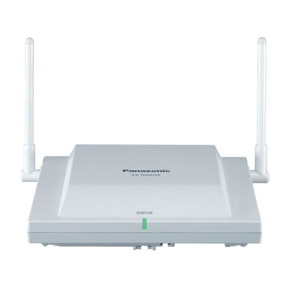
Quick Installation Guide DECT Cell Station Unit KX-TDA0155 Model No. KX-TDA0156 KX-TDA0158 Thank you for purchasing a Panasonic DECT Cell Station Unit. Please read this manual carefully before using this product and save this manual for future use. -
Page 2: Important Information
Important Information Important Information SAVE THESE INSTRUCTIONS Safety Notices Please observe the safety notices in this manual in order to avoid danger to users or other people, and prevent damage to property. The notices are classified as follows, according to the severity of injury or damage: WARNING This notice means that misuse could result in death or serious injury. - Page 3 Important Information – Locations where air ventilation is poor. – Locations that may be exposed to sulphurous gas, such as near hot springs. – Near devices that emit heat, such as heaters. – Near devices that emit electromagnetic noise, such as radios or televisions. –...
-
Page 4: Additional Information
Important Information Additional Information For users in the European Union only Information for Users on Collection and Disposal of Old Equipment and used Batteries These symbols on the products, packaging, and/or accompanying documents mean that used electrical and electronic products and batteries should not be mixed with general household waste. -
Page 5: Table Of Contents
Table of Contents Table of Contents 1 Overview ....................6 2 Procedure Overview ................11 3 Site Planning ..................13 4 Before Site Survey .................17 5 Site Survey Using the KX-TCA175/KX-TCA256/KX-TCA275/ KX-TCA355/KX-TCA364 .................22 6 After Site Survey ..................26 7 Connecting a Cell Station to the PBX ..........27 8 Wall Mounting ..................49 9 Troubleshooting ..................52 Quick Installation Guide... -
Page 6: Overview
1 Overview 1 Overview Names and Locations KX-TDA0155/KX-TDA0156 Antennas CS ID Number (ID: xxxxxxxxxx) RJ11 Modular DIP Switch KX-TDA0158 Antennas CS ID Number (ID: xxxxxxxxxx) DIP Switch RJ45 Modular LED Indications Indication Colour Description STATUS Green/Red CS status indication •... - Page 7 1 Overview Compatible PBX Cell Station Model No. MPR Software Version KX-TDA0155 KX-TDA15 PSMPR Software File Version 1.1000 or later KX-TDA30 PSMPR Software File Version 1.0000 or later KX-TDA100 PMPR Software File Version 1.1000 or later KX-TDA200 KX-TDA600 PLMPR Software File Version 2.2000 or later KX-TDE100 PMMPR Software File Version 1.0000 or later...
- Page 8 For more details about the Portable Station (PS), refer to the Operating Instructions of the PS. Maximum Number of CSs Supported by PBX Notice The CSs are for connection to specified Panasonic PBXs only. The following number of CSs can be supported by each PBX. Maximum Number...
-
Page 9: Required Distances Between Equipment
1 Overview Required Distances between Equipment CAUTION Maintain the distances listed below between equipment in order to prevent noise, interference or the disconnection of a conversation. (The distance may vary depending on the environment.) Equipment Distance CS and office equipment such as a computer, telex, fax More than 2 m machine, etc. - Page 10 1 Overview • Do not use this wireless system near another high-power cordless system such as DECT or SS wireless. Quick Installation Guide...
-
Page 11: Procedure Overview
PS software version: 3.027 or later – KX-TDA0158 software version: 6.033 or later – KX-TDA0155/KX-TDA0156 software version: any version 1. Investigate the installation site Refer to "3 Site Planning". Obtain a map of the CS installation site. Identify the service area required by the user on the map. - Page 12 2 Procedure Overview 4. Finish the site survey Refer to "6 After Site Survey". Turn off the PS. Stop supplying power, and return all DIP switches of each CS to the OFF position. 5. Connect the CS and PS to the PBX and test the operation Refer to "7 Connecting a Cell Station to the PBX".
-
Page 13: Site Planning
3 Site Planning 3 Site Planning Choosing the best site for the CS requires careful planning and testing of essential areas. The best location may not always be convenient for installation. Read the following information before installing the unit. Understanding Radio Waves Characteristics of Radio Waves The transmission of radio waves and the CS coverage area depend on the structure and materials of the building. - Page 14 3 Site Planning Object Material Transmission Tendency Wall Concrete The thicker they are, the less radio waves penetrate them. Ferroconcrete Radio waves can penetrate them, but the more iron there is, the more radio waves are reflected. Window Glass Radio waves usually penetrate them. Glass with wire net Radio waves can penetrate them, but tend to be reflected.
- Page 15 3 Site Planning CS Coverage Area The example below shows the size of the coverage area of 1 CS if it is installed in an area with no obstacles. Note Radio signal strength levels are measured during the site survey (refer to "5 Site Survey Using the KX-TCA175/KX-TCA256/KX-TCA275/KX-TCA355/KX-TCA364").
- Page 16 3 Site Planning If 1 CS cannot cover the entire service area, install additional CSs as required. Overlap the coverage areas of adjacent CSs. Where CS coverage areas overlap, the PS will start call handover to the next CS if the signal from one CS becomes weak.
-
Page 17: Before Site Survey
PS software version: 3.027 or later – KX-TDA0158 software version: 6.033 or later – KX-TDA0155/KX-TDA0156 software version: any version Note Display prompts for the site survey are only available in English. Checking the CS ID Number Check the CS ID number label attached to the CS. If the CS ID number label is not attached to the CS, check the CS ID number using the Maintenance Console. - Page 18 Setting and Installing the CS Temporarily for Site Survey Switch the Radio Signal Test switch from OFF to ON. Set the channel number switches as desired. Set the Power Supply Select switch as desired. KX-TDA0155/KX-TDA0156 Channel 0 Channel 1 Channel 2...
-
Page 19: Channel
4 Before Site Survey KX-TDA0158 Radio Signal Test Switch Power Supply Select Switch From the AC Adaptor (KX-A11)/ Battery Box (PSZZTD142CE) OFF: From the PBX Channel Number Switch DIP Switch Channel 0 Channel 1 Channel 2 Channel 3 Channel 4 Channel 5 Channel 6 Channel 7 Channel 8 Channel 9 Note If more than 1 CS is in Radio Signal Test mode, each CS must have a unique channel number. - Page 20 4 Before Site Survey KX-TDA0155/KX-TDA0156 KX-TDA0158 RJ11 Modular RJ45 Modular Telephone Cord Telephone Cord (PSJA1017Z) Power Supply Adaptor Power Supply Adaptor (PSZZ1TDA0142) (PSZZ1TDA0142) RJ11 Modular RJ11 Modular To AC Adaptor (KX-A11/KX-TCA1)/ To AC Adaptor (KX-A11)/ Battery Box (PSZZTD142CE) Battery Box (PSZZTD142CE)
- Page 21 4 Before Site Survey Install the CS temporarily for the site survey. Install the CS at least 2 m above the floor, and place the antennas so that they are pointing in directions that are 90 degrees apart (for antenna diversity), as follows: Note The illustration of the CS is based on the KX-TDA0158.
-
Page 22: Site Survey Using The Kx-Tca175/Kx-Tca256/Kx-Tca275/ Kx-Tca355/Kx-Tca364
– KX-TDA0158 software version: 6.033 or later – KX-TDA0155/KX-TDA0156 software version: any version Testing the Radio Signal Strength After locating the CS(s) temporarily, execute the Radio Signal Test using the PS. Directly after entering Radio Signal Test mode, the PS scans channel 0 for a CS that it can connect to. The channel to be scanned can be changed by pressing the appropriate keys 0 through 9. -
Page 23: Channel
5 Site Survey Using the KX-TCA175/KX-TCA256/KX-TCA275/KX-TCA355/KX-TCA364 consistently 2% or more, there may be interference from external wireless equipment. In this case, the results below may happen regardless of the radio signal strength level. If the error rate is consistently 2% or more without interference from external wireless equipment, it is likely that metallic materials in the surrounding structures are causing interference. -
Page 24: Channel
5 Site Survey Using the KX-TCA175/KX-TCA256/KX-TCA275/KX-TCA355/KX-TCA364 Repeat steps 1 and 2 for other CSs, and relocate the CSs when necessary. Overlap adjacent CS coverage areas where the radio signal strength level is "8" by 5 m to 10 m. Channel no. 0 Channel no. -
Page 25: Channel
PSs may decrease. This is due to interference between the CSs or wireless network traffic conditions. As a guideline, the maximum number of CSs in an area with a radio signal strength of "16" is 3 (for KX-TDA0155/KX-TDA0158)/4 (for KX-TDA0156). Notice The required software versions are as follows: –... -
Page 26: After Site Survey
Hold down the POWER button on the PS until the PS is turned OFF. Disconnect the CS from the AC adaptor/battery box or the PBX to stop supplying electricity. KX-TDA0155/KX-TDA0156 KX-TDA0158 Switch all DIP switches on the CS from ON to OFF. -
Page 27: Connecting A Cell Station To The Pbx
7 Connecting a Cell Station to the PBX 7 Connecting a Cell Station to the PBX Connection Examples for KX-TDA15 Refer to the following examples to connect a CS to the PBX. KX-TDA0158 connecting to KX-TDA15 Super Hybrid Port Cable Maximum Distance ø... - Page 28 7 Connecting a Cell Station to the PBX Super Hybrid Ports (RJ45) Port No. Signal Name Pin No. CS (RJ45) Pin No. Signal Name Master Quick Installation Guide...
- Page 29 7 Connecting a Cell Station to the PBX DLC8 card (RJ45) DLC8 Port No. Port No. Signal Name Pin No. CS 1 (RJ45) Signal Name Pin No. Master CS 2 (RJ45) Signal Name Pin No. Master Quick Installation Guide...
- Page 30 7 Connecting a Cell Station to the PBX CS 1 (RJ45) DLC8 card (RJ11) Signal Name Pin No. Port No. Signal Name Pin No. Master CS 2 (RJ45) Signal Name Pin No. Master Accessories and User-supplied Items for the CS Accessories (included): Screws ´...
- Page 31 7 Connecting a Cell Station to the PBX KX-TDA0155 connecting to KX-TDA15 Super Hybrid Port Cable Maximum Distance ø 0.4 mm: 222 m ø 0.5 mm: 347 m ø 0.6 mm: 500 m CAT 5: 347 m A Super Hybrid Port...
- Page 32 7 Connecting a Cell Station to the PBX Connection Examples for KX-TDA30 Refer to the following examples to connect a CS to the PBX. KX-TDA0158 connecting to KX-TDA30 Super Hybrid Port Cable Maximum Distance ø 0.4 mm: 222 m ø 0.5 mm: 347 m ø...
- Page 33 7 Connecting a Cell Station to the PBX Super Hybrid Ports or DLC4 card (RJ45) Port No. Signal Name Pin No. CS (RJ45) Pin No. Signal Name Master Super Hybrid Ports or DLC4 card (RJ11) Port No. Signal Name Pin No. CS (RJ45) Pin No.
- Page 34 7 Connecting a Cell Station to the PBX DLC8 card (RJ45) DLC8 Port No. Port No. Signal Name Pin No. CS 1 (RJ45) Signal Name Pin No. Master CS 2 (RJ45) Signal Name Pin No. Master Quick Installation Guide...
- Page 35 7 Connecting a Cell Station to the PBX CS 1 (RJ45) DLC8 card (RJ11) Signal Name Pin No. Port No. Signal Name Pin No. Master CS 2 (RJ45) Signal Name Pin No. Master Accessories and User-supplied Items for the CS Accessories (included): Screws ´...
- Page 36 7 Connecting a Cell Station to the PBX KX-TDA0155 connecting to KX-TDA30 Super Hybrid Port Cable Maximum Distance ø 0.4 mm: 222 m ø 0.5 mm: 347 m ø 0.6 mm: 500 m CAT 5: 347 m A Super Hybrid Port,...
- Page 37 7 Connecting a Cell Station to the PBX Connection Examples for KX-TDA100/KX-TDA200/KX-TDA600/KX-TDE100/ KX-TDE200/KX-TDE600 Refer to the following examples to connect a CS to the PBX. KX-TDA0156 connecting to KX-TDA100/KX-TDA200/KX-TDA600/KX-TDE100/KX-TDE200/ KX-TDE600 Note The illustration of the PBX is based on the KX-TDE200. CSIF8 Card Port 1 Cable...
- Page 38 7 Connecting a Cell Station to the PBX KX-TDA0158 connecting to KX-TDA100/KX-TDA200/KX-TDA600/KX-TDE100/KX-TDE200/ KX-TDE600 Note The illustration of the PBX is based on the KX-TDE200. DHLC8 Card Cable Maximum Distance ø 0.4 mm: 222 m ø 0.5 mm: 347 m ø 0.6 mm: 500 m CAT 5: 347 m...
- Page 39 Check the connection of CS and the PBX using the Maintenance Console. For information about how to view CS information using the Maintenance Console, refer to "Utility—CS Information" in the PC Programming Manual or the On-line Help for your PBX. KX-TDA0155 connecting to KX-TDA100/KX-TDA200/KX-TDA600/KX-TDE100/KX-TDE200/ KX-TDE600 Note The illustration of the PBX is based on the KX-TDE200.
- Page 40 7 Connecting a Cell Station to the PBX Connection Examples for KX-NCP500/KX-NCP1000 Refer to the following examples to connect a CS to the PBX. KX-TDA0158 connecting to KX-NCP500/KX-NCP1000 Note The illustration of the PBX is based on the KX-NCP500. DHLC4 Card Cable Maximum Distance ø...
- Page 41 7 Connecting a Cell Station to the PBX DHLC4 card (RJ45) Pin No. Signal Name Port No. CS 1 (RJ45) Signal Name Pin No. Master Quick Installation Guide...
- Page 42 7 Connecting a Cell Station to the PBX DLC8/DLC16 card (RJ45) Pin No. Signal Name Port No. DLC8 Port No.: 1 2 3 4 5 6 7 8 10 11 12 13 14 15 16 DLC16 CS 1 (RJ45) Pin No. Signal Name Master CS 2 (RJ45)
- Page 43 CS information using the Maintenance Console, refer to "Utility—CS Information" in the PC Programming Manual or the On-line Help for your PBX. KX-TDA0155 connecting to KX-NCP500/KX-NCP1000 Note The illustration of the PBX is based on the KX-NCP500.
- Page 44 7 Connecting a Cell Station to the PBX Connecting the CS Connect the cable from the PBX to the CS. KX-TDA0155/KX-TDA0156 KX-TDA0158 RJ11 Modular RJ45 Modular To PBX To PBX Pass the cable through the groove of the CS (in any direction depending on your preference).
- Page 45 7 Connecting a Cell Station to the PBX Registering the PS The PS must be registered to the PBX before it can be used. Programming of both the PS and PBX is required. A Proprietary Telephone (PT) with multiline display (e.g., KX-T7636 6-line display) is required to perform the PBX system programming.
- Page 46 7 Connecting a Cell Station to the PBX Setting the PIN for PS Using the KX-TCA175/KX-TCA275 Press POWER Select Select for 2 seconds. "Setting Handset". "System Option". If required System Lock Password Select 4 digits "Change PIN". PIN for PS Registration C.Tone 1 to 8 digits 1234...
- Page 47 7 Connecting a Cell Station to the PBX When registering the PS for the first time, it is possible to select the desired language for the display. (You do not need to enter the PS system programming mode when registering for the first time.) If required C.Tone C.Tone...
- Page 48 7 Connecting a Cell Station to the PBX • The PS is within range. [691] PS No. 001 to max. no. ENTER ENTER of PSs (3 digits) If "Rejected" or "Time out" is displayed CLEAR Press "CLEAR". Press "YES". (HOLD) If "Rejected"...
-
Page 49: Wall Mounting
Make sure that the screw heads are at the same distance from the wall. • Install the screws perpendicular to the wall. Hook the CS on the screw heads. KX-TDA0155/KX-TDA0156 Washer Drive the screw to this point. Quick Installation Guide... - Page 50 8 Wall Mounting KX-TDA0158 Washer Drive the screw to this point. Place the antennas so that they are pointing in directions that are 90 degrees apart (for antenna diversity), as follows: 45º 90º 45º Quick Installation Guide...
- Page 51 8 Wall Mounting Reference for Wall Mounting Please copy this page and use as a reference for wall mounting. Install a screw here. 83 mm Install a screw here. Note Make sure to set the print size to correspond with the size of this page. If the dimension of the paper output still deviates slightly from the measurement indicated here, use the measurement indicated here.
-
Page 52: Troubleshooting
9 Troubleshooting 9 Troubleshooting PROBLEM PROBABLE CAUSE SOLUTION • • • The LED of the CS does not The optional service card is Install the card properly. change to Green ON. not working. • • CS is not connected Make sure that the cable is connected properly. - Page 53 When the PS software version is 3.027 or later, the maximum number of CSs in an area with a radio signal strength of "16" is 3 (for KX-TDA0155)/4 (for KX-TDA0156)/3 (for KX-TDA0158 with a software version of 6.033 or later). Also, the maximum number...
- Page 54 1-62, 4-chome, Minoshima, Hakata-ku, Fukuoka 812-8531, Japan Copyright: This material is copyrighted by Panasonic System Networks Co., Ltd., and may be reproduced for internal use only. All other reproduction, in whole or in part, is prohibited without the written consent of Panasonic System Networks Co., Ltd.