Table of Contents
Advertisement
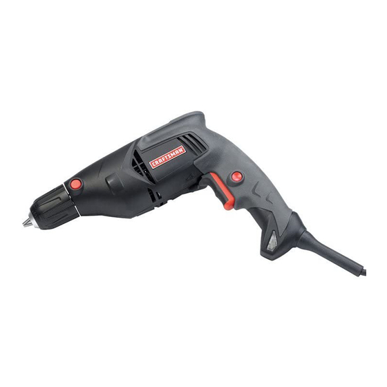
OPERATOR'S MANUAL
3/8 in. DRILL
VARIABLE SPEED
DOUBLE INSULATED
Model No.
315.101140
:
WARNING
To reduce the risk of injury,
the user must read and understand the
operator's manual before using this product.
Customer Help Line: 1-800-932-3188
Sears, Roebuck and Co., 3333 Beverly Rd., Hoffman Estates, IL 60179 USA
Visit the Craftsman web page: www.sears.com/craftsman
983000-730
11-14-05 (REV:00)
Save this manual for future reference
1
Advertisement
Table of Contents

Related Manuals for Craftsman 315.101140


Summary of Contents for Craftsman 315.101140
- Page 1 Customer Help Line: 1-800-932-3188 Sears, Roebuck and Co., 3333 Beverly Rd., Hoffman Estates, IL 60179 USA Visit the Craftsman web page: www.sears.com/craftsman Save this manual for future reference 983000-730 11-14-05 (REV:00)
-
Page 2: Table Of Contents
If this Craftsman tool fails to give complete satisfaction within one year from date of purchase, RETURN IT TO THE NEAREST SEARS STORE IN THE UNITED STATES, and Sears will replace it, free of charge. If this Craftsman tool is used for commercial or rental purposes, this warranty applies for only 90 days from the date of purchase. -
Page 3: General Safety Rules
GENERAL SAFETY RULES n Remove any adjusting key or wrench before turning WARNING! Read all instructions. Failure to follow the power tool on. A wrench or a key left attached to all instructions listed below may result in electric a rotating part of the power tool may result in personal shock, fire and/or serious injury. -
Page 4: Specific Safety Rules
GENERAL SAFETY RULES Maintenance section of this manual. Use of unau- SERVICE thorized parts or failure to follow Maintenance instruc- n Have your power tool serviced by a qualified repair tions may create a risk of shock or injury. person using only identical replacement parts. This will ensure that the safety of the power tool is main- WARNING! To reduce risk of injury, user must read... -
Page 5: Symbols
SYMBOLS Some of the following symbols may be used on this tool. Please study them and learn their meaning. Proper interpreta- tion of these symbols will allow you to operate the tool better and safer. SYMBOL NAME DESIGNATION/EXPLANATION Volts Voltage Amperes Current Hertz... - Page 6 SYMBOLS The following signal words and meanings are intended to explain the levels of risk associated with this product. SYMBOL SIGNAL MEANING Indicates an imminently hazardous situation, which, if not avoided, will DANGER: result in death or serious injury. Indicates a potentially hazardous situation, which, if not avoided, could WARNING: result in death or serious injury.
-
Page 7: Electrical
ELECTRICAL EXTENSION CORDS DOUBLE INSULATION When using a power tool at a considerable distance from Double insulation is a concept in safety in electric power a power source, be sure to use an extension cord that has tools, which eliminates the need for the usual three-wire the capacity to handle the current the tool will draw. -
Page 8: Features
FEATURES PRODUCT SPECIFICATIONS Switch Trigger..........Variable Speed Torque............Maximum 76 in.lb. Chuck ........3/8 in. Single Sleeve Keyless Input ........120 V, 60 Hz, AC only, 5.5 Amps No Load Speed ..........0-1500/min. Net Weight..........3.5 lbs. (1.6 kg) LEVELS KEYLESS CHUCK LOCK-ON SPINDLE LOCK BUTTON BUTTON DIRECTION OF... -
Page 9: Assembly
ASSEMBLY UNPACKING WARNING If any parts are missing do not operate This product has been shipped completely assembled. this tool until the missing parts are replaced. Failure n Carefully remove the tool and any accessories from the to do so could result in possible serious personal box. -
Page 10: Operation
OPERATION DIRECTION OF ROTATION SELECTOR WARNING Do not allow familiarity with tools to make you careless. Remember that a careless (FORWARD/REVERSE) fraction of a second is sufficient to inflict serious See Figure 2. injury. The direction of bit rotation is reversible and is controlled by a selector located above the switch trigger. - Page 11 OPERATION INSTALLING BITS See Figures 3 - 4. n Unplug the drill. n Depress the spindle lock button. n While keeping the button depressed, rotate the chuck in either direction until it clicks into a position that will not allow it to rotate. n Keeping the spindle lock button depressed, rotate the chuck counterclockwise to open the chuck jaws.
- Page 12 OPERATION LEVEL DRILLING See Figure 5. See Figure 5. When drilling hard smooth surfaces, use a center punch This dril has a level on top of the motor housing. It can to mark the desired hole location. This will prevent the drill help to keep the drill bit level during operation.
-
Page 13: Maintenance
MAINTENANCE MALLET WARNING When servicing, use only identical Craftsman replacement parts. Use of any other parts CHUCK JAWS may create a hazard or cause product damage. WARNING Always wear safety goggles or safety glasses with side shields during power tool operation or when blowing dust. -
Page 14: Exploded View And Parts List
CRAFTSMAN PRODUCT NAME – MODEL NUMBER 315.101140 The model number will be found on a plate attached to the motor housing. Always mention the model number in all correspondence regarding your DRILL or when ordering repair parts. SEE BACK PAGE FOR PARTS ORDERING INSTRUCTIONS...