Table of Contents
Advertisement
Telephone Equipment
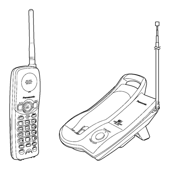
KX-TC2100BXB
KX-TC2100BXS
KX-TC2100BXT
KX-TC2100BXW
Cordless Phone
Black Version
Silver Version
Metallic Black Version
White Version
(for Asia, Middle Near East and Other Areas)
© 2005 Panasonic Communications Co., Ltd. All
rights
reserved.
distribution is a violation of law.
ORDER NO. KM40507814CE
Unauthorized
copying
and
Advertisement
Table of Contents
Troubleshooting

Related Manuals for Panasonic KX-TC2100BXB


Summary of Contents for Panasonic KX-TC2100BXB
- Page 1 KX-TC2100BXB KX-TC2100BXS KX-TC2100BXT KX-TC2100BXW Cordless Phone Black Version Silver Version Metallic Black Version White Version (for Asia, Middle Near East and Other Areas) © 2005 Panasonic Communications Co., Ltd. All rights reserved. Unauthorized copying distribution is a violation of law.
-
Page 2: Table Of Contents
KX-TC2100BXB / KX-TC2100BXS / KX-TC2100BXT / KX-TC2100BXW Note: Because CONTENTS 4 is the extract from the Operating Instructions of this model, it is subject to change without notice. You can download and refer to the original Operating Instructions on TSN Server for further information. - Page 3 KX-TC2100BXB / KX-TC2100BXS / KX-TC2100BXT / KX-TC2100BXW 26.2. Handset 30 CIRCUIT BOARD (BASE UNIT) 26.3. Accessories and Packing Materials 30.1. Component View 27 FOR SCHEMATIC DIAGRAM 30.2. Flow Solder Side View 27.1. Base Unit (SCHEMATIC DIAGRAM (BASE UNIT)) 31 CIRCUIT BOARD (HANDSET) 27.2.
-
Page 4: About Lead Free Solder (Pbf: Pb Free)
KX-TC2100BXB / KX-TC2100BXS / KX-TC2100BXT / KX-TC2100BXW 1 ABOUT LEAD FREE SOLDER (PbF: Pb free) Note: In the information below, Pb, the symbol for lead in the periodic table of elements, will refer to standard solder or solder that contains lead. -
Page 5: How To Recognize That Pb Free Solder Is Used
KX-TC2100BXB / KX-TC2100BXS / KX-TC2100BXT / KX-TC2100BXW 1.2. How to recognize that Pb Free Solder is Used (Example: Handset P.C.B.) DTCOUT TXPOWER C873 C852 AUTO C872 R843 C851 C861 C866 R837 C865 C864 C853 R831 Q802 LED703 Q804 R848 C854... -
Page 6: Operating Instructions
KX-TC2100BXB / KX-TC2100BXS / KX-TC2100BXT / KX-TC2100BXW 4 OPERATING INSTRUCTIONS 4.1. Battery 4.1.1. Recharge 4.1.2. Battery information 4.1.3. Battery Replacement... -
Page 7: Location Of Controls
KX-TC2100BXB / KX-TC2100BXS / KX-TC2100BXT / KX-TC2100BXW 4.2. Location of Controls 4.2.1. Base Unit 4.2.2. Handset... -
Page 8: Connection
KX-TC2100BXB / KX-TC2100BXS / KX-TC2100BXT / KX-TC2100BXW 4.3. Connection... -
Page 9: Troubleshooting
KX-TC2100BXB / KX-TC2100BXS / KX-TC2100BXT / KX-TC2100BXW 4.4. Troubleshooting... -
Page 10: Disassembly Instructions
KX-TC2100BXB / KX-TC2100BXS / KX-TC2100BXT / KX-TC2100BXW 5 DISASSEMBLY INSTRUCTIONS Shown in Fig.- To Remove Remove Cabinet Cover Screws (2.6 × 12)....... (A) × 4 Main P.C. Board Main P.C. Board... - Page 11 KX-TC2100BXB / KX-TC2100BXS / KX-TC2100BXT / KX-TC2100BXW Shown in Fig.- To Remove Remove Cabinet Cover Battery compartment cover. Screws (2.6 × 12)......(B) × 2 Follow the procedure. Main P. C. Board Screw (2.6 × 12)......(C) × 1 Main P. C. Board...
-
Page 12: Troubleshooting Guide
KX-TC2100BXB / KX-TC2100BXS / KX-TC2100BXT / KX-TC2100BXW 6 TROUBLESHOOTING GUIDE Cross Reference: Check Power (P.13) Bell Reception (P.14) Check Battery Charge (P.15) Check Link (P.16) Check Handset Transmission (P.17) Check Handset Reception (P.18) -
Page 13: Check Power
KX-TC2100BXB / KX-TC2100BXS / KX-TC2100BXT / KX-TC2100BXW 6.1. Check Power Cross Reference: Note: Reset Circuit (P.34) *CPU: IC201 Power Supply Circuit (P.33) Cross Reference: Note: Charge Circuit (P.35) *CPU: IC701 *: Each measurement points are shown in CIRCUIT BOARD (BASE UNIT) (P.61) or CIRCUIT BOARD (HANDSET) (P.63) -
Page 14: Bell Reception
KX-TC2100BXB / KX-TC2100BXS / KX-TC2100BXT / KX-TC2100BXW 6.2. Bell Reception Cross Reference: Note: Check Link (P.16) *CPU: IC201 Telephone Line Interface (P.35) Cross Reference: Note: Check Link (P.16) *CPU: IC701 *: Each measurement points are shown in CIRCUIT BOARD (BASE UNIT) (P.61) or CIRCUIT BOARD (HANDSET) (P.63) -
Page 15: Check Battery Charge
KX-TC2100BXB / KX-TC2100BXS / KX-TC2100BXT / KX-TC2100BXW 6.3. Check Battery Charge Cross Reference: Note: Charge Circuit (P.35) *CPU: IC201 Cross Reference: Note: Reset Circuit (P.39) *CPU: IC701 *: Each measurement points are shown in CIRCUIT BOARD (BASE UNIT) (P.61) or CIRCUIT BOARD (HANDSET) (P.63) -
Page 16: Check Link
KX-TC2100BXB / KX-TC2100BXS / KX-TC2100BXT / KX-TC2100BXW 6.4. Check Link **: Refer to Adjustment (P.20) Note: *CPU: IC201 *RF IC: IC401 *: Each measurement points are shown in CIRCUIT BOARD (BASE UNIT) (P.61) or CIRCUIT BOARD (HANDSET) (P.63) -
Page 17: Check Handset Transmission
KX-TC2100BXB / KX-TC2100BXS / KX-TC2100BXT / KX-TC2100BXW **: Refer to Adjustment (P.23). Note: *CPU: IC701 *RF IC: IC801 *: Each measurement points are shown in CIRCUIT BOARD (BASE UNIT) (P.61) or CIRCUIT BOARD (HANDSET) (P.63) 6.5. Check Handset Transmission Cross Reference:... -
Page 18: Check Handset Reception
KX-TC2100BXB / KX-TC2100BXS / KX-TC2100BXT / KX-TC2100BXW 6.6. Check Handset Reception Cross Reference: SIGNAL ROUTE (P.41) -
Page 19: Adjustments (Base Unit)
KX-TC2100BXB / KX-TC2100BXS / KX-TC2100BXT / KX-TC2100BXW 7 ADJUSTMENTS (BASE UNIT) If your unit has below symptoms, adjust or confirm each item using remedy column from the table. Symptom Remedy* The base unit does not respond to a call from handset. -
Page 20: How To Change The Channel
KX-TC2100BXB / KX-TC2100BXS / KX-TC2100BXT / KX-TC2100BXW 7.2. How to change the channel Note: Refer to Adjustment Standard (Base Unit) (P.21) for connection. 7.3. Adjustment Adjustment Items Test Mode Adjustment *Procedure Check or Point Replace Parts • Adjust T404 so that the reading of the Digital Voltmeter is 1.5 ± 0.3 V. - Page 21 KX-TC2100BXB / KX-TC2100BXS / KX-TC2100BXT / KX-TC2100BXW...
-
Page 22: Adjustments (Handset)
KX-TC2100BXB / KX-TC2100BXS / KX-TC2100BXT / KX-TC2100BXW 8 ADJUSTMENTS (HANDSET) If your unit has below symptoms, adjust or confirm each item using remedy column from the table. Symptom Remedy* The movement of Battery Low Indicator is wrong. Make confirmation in item (A) The base unit does not respond to a call from the handset. -
Page 23: How To Change The Channel
KX-TC2100BXB / KX-TC2100BXS / KX-TC2100BXT / KX-TC2100BXW 8.2. How to change the channel 8.3. Adjustment Adjustment Items Test Mode Adjustment *Procedure Check or Point Replace Parts (A) Battery Low 3ch Talk 1. Adjust the power supply voltage to DC 3.60V and confirm so that the... - Page 24 KX-TC2100BXB / KX-TC2100BXS / KX-TC2100BXT / KX-TC2100BXW TALK FLASH LED701 REDIAL PROGRAM RINGER PAUSE OUTPUT LOUD...
-
Page 25: Rf Specification
KX-TC2100BXB / KX-TC2100BXS / KX-TC2100BXT / KX-TC2100BXW 9 RF SPECIFICATION 9.1. Base Unit Item Value Refer to -.* Remarks TX Frequency 46.670 MHz ± 700 Hz ADJUSTMENTS (BASE UNIT) (C) at CH3 TX Power more than 1dBm ADJUSTMENTS (BASE UNIT) (D) -
Page 26: Frequency Table (Mhz)
KX-TC2100BXB / KX-TC2100BXS / KX-TC2100BXT / KX-TC2100BXW 11 FREQUENCY TABLE (MHz) BASE UNIT HANDSET Channel Transmit Frequency Receive Frequency Transmit Frequency Receive Frequency 46.610 49.670 49.670 46.610 46.630 49.845 49.845 46.630 46.670 49.860 49.860 46.670 46.710 49.770 49.770 46.710 46.730 49.875... -
Page 27: Explanation Of Cpu Data Communication
KX-TC2100BXB / KX-TC2100BXS / KX-TC2100BXT / KX-TC2100BXW 12 EXPLANATION OF CPU DATA COMMUNICATION 12.1. STAND-BY -> TALK, TALK -> STAND-BY *: The channel is changed if the noise interferes with the conversation. -
Page 28: Ringing
KX-TC2100BXB / KX-TC2100BXS / KX-TC2100BXT / KX-TC2100BXW 12.2. Ringing... -
Page 29: Changing The Channel
KX-TC2100BXB / KX-TC2100BXS / KX-TC2100BXT / KX-TC2100BXW 12.3. Changing the Channel... -
Page 30: Ports For Transmitting And Receiving Of Data
KX-TC2100BXB / KX-TC2100BXS / KX-TC2100BXT / KX-TC2100BXW 12.4. Ports for transmitting and receiving of data Handset: Base Unit: transmitting (TX) ... 25 Pin transmitting (TX) ... 23 Pin receiving (RX) ... 12 Pin receiving (RX) ... 10 Pin 12.5. Waveform of DATA used for cordless transmission and reception The DATA which is transmitted from the Handset to the Base Unit is combination of DATA 0, DATA 1, DATA Delimit. - Page 31 KX-TC2100BXB / KX-TC2100BXS / KX-TC2100BXT / KX-TC2100BXW...
-
Page 32: Block Diagram (Base Unit)
KX-TC2100BXB / KX-TC2100BXS / KX-TC2100BXT / KX-TC2100BXW 14 CIRCUIT OPERATION (BASE UNIT) 14.1. Outline Base unit consists of the following ICs as shown in BLOCK DIAGRAM (BASE UNIT) (P.31). • CPU: IC201 − Controlling the whole system − Forming/analyzing all data signals (ACK, CMD signal etc.) −... -
Page 33: Power Supply Circuit
KX-TC2100BXB / KX-TC2100BXS / KX-TC2100BXT / KX-TC2100BXW 14.2. Power Supply Circuit The power supply to the CPU and RF IC from AC Adaptor (+12V) is shown in the diagram below. The base unit power supply is DC12V. The handset power is supplied from DC 3.6V battery (Nickel-Cadmium battery) which is installed in the handset. -
Page 34: Reset Circuit
KX-TC2100BXB / KX-TC2100BXS / KX-TC2100BXT / KX-TC2100BXW 14.3. Reset Circuit After power supply from AC adaptor, the reset signal for CPU is making in IC401. Refer to the below waveform. <Fig. 2> <Fig. 3>... -
Page 35: Charge Circuit
KX-TC2100BXB / KX-TC2100BXS / KX-TC2100BXT / KX-TC2100BXW 14.4. Charge Circuit Circuit Operation: When charging the handset on the base unit, the charge current is as follows; DC12V → L101 → D102 → L103 → CH+(Base) → +CONTACT J601(Handset) → L602 → D602 → CN1-1 → Battery →... -
Page 36: Transmitter/Receiver
KX-TC2100BXB / KX-TC2100BXS / KX-TC2100BXT / KX-TC2100BXW 14.6. Transmitter/Receiver Base Unit and Handset mainly consist of RF (Radio Frequency) IC and CPU. Base Unit and Handset transmit/receive voice signal and data signal through the antenna on carrier frequency. Signal Path: *Refer to CDL TX/RX in SIGNAL ROUTE (P.41). - Page 37 KX-TC2100BXB / KX-TC2100BXS / KX-TC2100BXT / KX-TC2100BXW 14.6.3. RF signal operation/control and PLL operation (RF UNIT) Base unit radio frequency signal received by antenna passes through duplexer (DPX401). RF signal is amplified by RF AMP. RF signal received from RF IC is mixed with RX local frequency at Mixer to generate 10.695 MHz wide band IF.
- Page 38 KX-TC2100BXB / KX-TC2100BXS / KX-TC2100BXT / KX-TC2100BXW...
-
Page 39: Block Diagram (Handset)
KX-TC2100BXB / KX-TC2100BXS / KX-TC2100BXT / KX-TC2100BXW 16 CIRCUIT OPERATION (HANDSET) 16.1. Outline Handset consists of the following ICs as shown in BLOCK DIAGRAM (HANDSET) (P.38). • CPU: IC701 − Forming/analyzing all data signals (ACK or CMD signal) − All interfaces (ex; LED, Key, Buzzer, Detector Circuit, Charge/Battery Low) −... -
Page 40: Battery Low / Power Down Detector
KX-TC2100BXB / KX-TC2100BXS / KX-TC2100BXT / KX-TC2100BXW 16.3. Battery Low / Power Down Detector Circuit Operation: “Battery Low” and “Power Down” are detected by RF IC which check the voltage from battery. Shortly, every detected blocks are inside of RF IC. The detected voltage is as follows;... -
Page 41: Signal Route
KX-TC2100BXB / KX-TC2100BXS / KX-TC2100BXT / KX-TC2100BXW 17 SIGNAL ROUTE Each signal route is as follows. -
Page 42: Cpu Data (Base Unit)
KX-TC2100BXB / KX-TC2100BXS / KX-TC2100BXT / KX-TC2100BXW 18 CPU DATA (Base Unit) 18.1. IC201... -
Page 43: Cpu Data (Handset)
KX-TC2100BXB / KX-TC2100BXS / KX-TC2100BXT / KX-TC2100BXW 19 CPU DATA (Handset) 19.1. IC701... -
Page 44: Rf Ic (Base Unit And Handset) 20.1. Base Unit: Ic401, Handset: Ic801
KX-TC2100BXB / KX-TC2100BXS / KX-TC2100BXT / KX-TC2100BXW 20 RF IC (Base Unit and Handset) 20.1. Base Unit: IC401, Handset: IC801... -
Page 45: How To Replace The Flat Package Ic
KX-TC2100BXB / KX-TC2100BXS / KX-TC2100BXT / KX-TC2100BXW 21 HOW TO REPLACE THE FLAT PACKAGE IC Even if you do not have the special tools (for example, a spot heater) to remove the Flat IC, with some solder (large amount), a soldering iron and a cutter knife, you can easily remove the ICs that have more than 100 pins. -
Page 46: Flat Package Ic Installation Procedure
KX-TC2100BXB / KX-TC2100BXS / KX-TC2100BXT / KX-TC2100BXW 21.3. FLAT PACKAGE IC INSTALLATION PROCEDURE 1. Temporarily fix the FLAT PACKAGE IC, soldering the two marked pins. *Check the accuracy of the IC setting with the corresponding soldering foil. 2. Apply flux to all pins of the FLAT PACKAGE IC. -
Page 47: Cabinet And Electrical Parts (Base Unit)
KX-TC2100BXB / KX-TC2100BXS / KX-TC2100BXT / KX-TC2100BXW 22 CABINET AND ELECTRICAL PARTS (BASE UNIT) -
Page 48: Cabinet And Electrical Parts (Handset)
KX-TC2100BXB / KX-TC2100BXS / KX-TC2100BXT / KX-TC2100BXW 23 CABINET AND ELECTRICAL PARTS (HANDSET) -
Page 49: Accessories And Packing Materials
KX-TC2100BXB / KX-TC2100BXS / KX-TC2100BXT / KX-TC2100BXW 24 ACCESSORIES AND PACKING MATERIALS... -
Page 50: Terminal Guide Of The Ics, Transistors And Diodes
KX-TC2100BXB / KX-TC2100BXS / KX-TC2100BXT / KX-TC2100BXW 25 TERMINAL GUIDE OF THE ICs, TRANSISTORS AND DIODES 25.1. Base Unit 25.2. Handset... -
Page 51: Replacement Parts List
KX-TC2100BXB / KX-TC2100BXS / KX-TC2100BXT / KX-TC2100BXW 26 REPLACEMENT PARTS LIST 1. RTL (Retention Time Limited) Ref. Part No. Part Name & Description Remarks Note: PQGT17774Y NAME PLATE (for KX-TC2100BXT) The marking (RTL) indicates that the Retention Time is PQGT17770Y... - Page 52 KX-TC2100BXB / KX-TC2100BXS / KX-TC2100BXT / KX-TC2100BXW Ref. Part No. Part Name & Description Remarks Ref. Part No. Part Name & Description Remarks T402 PQL04B001 COIL R420 ERJ3GEYJ683 T403 G2BRC0000007 COIL R421 ERJ3GEYJ103 T404 PQL04B002 COIL R422 ERJ3GEYJ682 6.8K (CERAMIC FILTERS)
-
Page 53: Handset
KX-TC2100BXB / KX-TC2100BXS / KX-TC2100BXT / KX-TC2100BXW Ref. Part No. Part Name & Description Remarks Ref. Part No. Part Name & Description Remarks C428 ECJ1VC1H271J 270P PQKF10667Y3 CABINET COVER (for ABS-HB TC2100BXS) C429 ECUV1H152KBV 0.0015 PQKF10667Y4 CABINET COVER (for ABS-HB... -
Page 54: Accessories And Packing Materials
KX-TC2100BXB / KX-TC2100BXS / KX-TC2100BXT / KX-TC2100BXW Ref. Part No. Part Name & Description Remarks Ref. Part No. Part Name & Description Remarks R713 ERJ3GEYJ222 2.2K C821 ECJ1VB1H472K 0.0047 R714 ERJ3GEYJ104 100K C822 ECUV1C104KBV R715 ERJ3GEYJ221 C823 ECUV1H103KBV 0.01 R729 ERJ3GEYJ222 2.2K... - Page 55 KX-TC2100BXB / KX-TC2100BXS / KX-TC2100BXT / KX-TC2100BXW Ref. Part No. Part Name & Description Remarks PQPP10105Z PROTECTION COVER (for Handset) PQPP10092Z PROTECTION COVER PQPK14627Z GIFT BOX...
- Page 56 KX-TC2100BXB / KX-TC2100BXS / KX-TC2100BXT / KX-TC2100BXW Memo...
-
Page 57: For Schematic Diagram
KX-TC2100BXB / KX-TC2100BXS / KX-TC2100BXT / KX-TC2100BXW 27 FOR SCHEMATIC DIAGRAM 27.1. Base Unit (SCHEMATIC DIAGRAM (BASE UNIT)) 1. DC voltage measurements are taken with an oscilloscope or a tester with a ground. 2. The schematic diagrams and circuit board may be modified at any time with the development of new technology. -
Page 58: Schematic Diagram (Base Unit)
KX-TC2100BXB / KX-TC2100BXS / KX-TC2100BXT / KX-TC2100BXW... -
Page 59: Schematic Diagram (Handset)
KX-TC2100BXB / KX-TC2100BXS / KX-TC2100BXT / KX-TC2100BXW... - Page 60 KX-TC2100BXB / KX-TC2100BXS / KX-TC2100BXT / KX-TC2100BXW...
- Page 61 KX-TC2100BXB / KX-TC2100BXS / KX-TC2100BXT / KX-TC2100BXW L102 L101 ANT1 D102 C102 SA301 PO301 R104 L301 Q102 C469 C104 Q103 C302 R307 Q301 Q302 D308 Q303 D307 C462 C308 C460 R314 Q304 DV401 C431 C312 C444 C443 PQUP11329Z X401 C435...
- Page 62 KX-TC2100BXB / KX-TC2100BXS / KX-TC2100BXT / KX-TC2100BXW...
- Page 63 KX-TC2100BXB / KX-TC2100BXS / KX-TC2100BXT / KX-TC2100BXW BLACK ANT2 DPX1 C834 L701 X701 C701 D701 VBAT L603 D602 D601 MIC1 MIC2 C601 J601 J602...
- Page 64 KX-TC2100BXB / KX-TC2100BXS / KX-TC2100BXT / KX-TC2100BXW TALK FLASH LED701 REDIAL PROGRAM RINGER PAUSE OUTPUT LOUD...
- Page 65 KX-TC2100BXB / KX-TC2100BXS / KX-TC2100BXT / KX-TC2100BXW I.N./N KXTC2100BXB KXTC2100BXS KXTC2100BXT KXTC2100BXW...