Table of Contents
Advertisement
Quick Links
CHAPTER 1. GENERAL DESCRIPTION
[1]
Specifications ......................................... . ....... 1-1
[2]
Operation panel...................................... . ....... 1-2
[3]
Transmittable documents ....................... . ....... 1-3
[4]
Installation .............................................. . ....... 1-4
[5]
Quick setup guide .................................. . ....... 1-8
[6]
Quick reference guide ............................ . ....... 1-9
[7]
Option imaging film specifications.......... . ....... 1-9
[1]
Adjustments ........................................... . ....... 2-1
[2]
Diagnostics and service soft switch ....... . ....... 2-2
[3]
Troubleshooting ..................................... . ..... 2-20
[4]
Error code table...................................... . ..... 2-21
CHAPTER 3. MECHANISM BLOCKS
[1]
General description ................................ . ....... 3-1
[2]
Disassembly and assembly procedures. . ....... 3-3
CHAPTER 4. DIADRAMS
[1]
Block diagram ........................................ . ....... 4-1
[2]
Wiring diagram ....................................... . ....... 4-2
[3]
Point-to-point diagram............................ . ....... 4-3
Parts marked with "
" are important for maintaining the safety of the set. Be sure to replace these parts with specified ones for
maintaining the safety and performance of the set.
SERVICE MANUAL
CONTENTS
SHARP CORPORATION
No. 00ZUXP115USME
FACSIMILE
MODEL
MODEL
SELECTION CODE DESTINATION
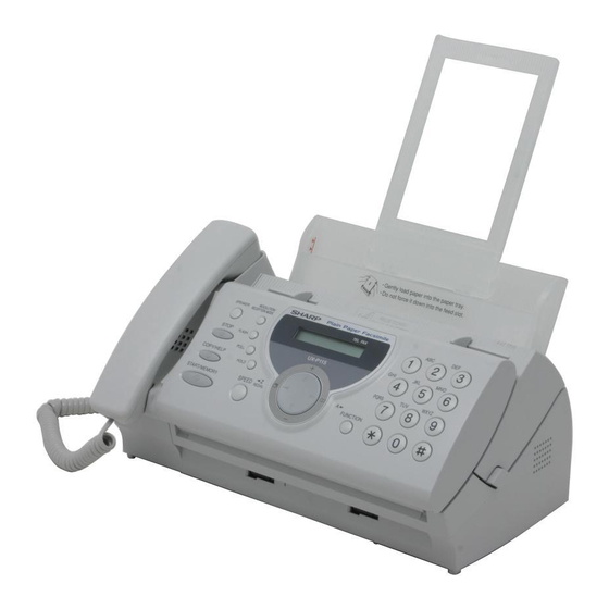
UX-P115
CHAPTER 5. CIRCUIT DESCRIPTION
[1]
Circuit description ..........................................5-1
[2]
Circuit description of control PWB ................5-2
[3]
Circuit description of TEL/LIU PWB...............5-9
[4]
Circuit description of power supply PWB ......5-12
[5]
Circuit description of CIS unit ......................5-12
CHAPTER 6. CIRCUIT SCHEMATICS AND PARTS
LAYOUT
[1]
Control PWB circuit .......................................6-1
[2]
TEL/LIU PWB circuit......................................6-9
[3]
Power supply PWB circuit ...........................6-12
[4]
Operation Panel PWB circuit .......................6-14
[1]
Protocol .........................................................7-1
[2]
Power on sequence.......................................7-2
[1]
Service tools ..................................................8-1
[2]
Changing the record paper size ....................8-4
This document has been published to be used
for after sales service only.
The contents are subject to change without notice.
UX-P115U
UX-P115
U
U.S.A.
Advertisement
Table of Contents

Related Manuals for Sharp UX-P115


Summary of Contents for Sharp UX-P115
-
Page 1: Table Of Contents
UX-P115U SERVICE MANUAL No. 00ZUXP115USME FACSIMILE UX-P115 MODEL MODEL SELECTION CODE DESTINATION UX-P115 U.S.A. CONTENTS CHAPTER 1. GENERAL DESCRIPTION CHAPTER 5. CIRCUIT DESCRIPTION Specifications ..........1-1 Circuit description ..........5-1 Operation panel..........1-2 Circuit description of control PWB ....5-2 Transmittable documents ....... - Page 2 UX-P115U CAUTION FOR BATTERY REPLACEMENT (French) ATTENTION (Danish) ADVARSEL ! Il y a danger d'explosion s' il y a remplacement incorrect Lithiumbatteri-Eksplosionsfare ved fejlagtig håndtering. de la batterie. Remplacer uniquement avec une batterie du Udskiftning må kun ske med batteri af samme fabrikat og type. même type ou d'un type recommandé...
-
Page 3: Specifications
As a part of our policy of continuous improvement, SHARP reserves the right to make design and specification changes for product improvement without prior notice. The performance specifications figures indicated are nominal values of production units. There may be some deviations from these values in individual units. -
Page 4: Operation Panel
UX-P115U [2] Operation panel RESOLUTION/ SPEAKER RECEPTION MODE TEL FAX STOP FLASH POLL PQRS WXYZ COPY/HELP HOLD SPEED START/MEMORY FUNCTION REDIAL 10 11 1. SPEAKER key 8. Number keys Press this key to listen to the line and fax tones through the speaker Use these keys to dial numbers, and enter numbers and letters when when faxing a document. -
Page 5: Transmittable Documents
UX-P115U [3] Transmittable documents 5. Automatic Document Feeder Capacity Number of pages that can be placed into the feeder at anytime is as 1. Document Sizes follows: Normal size: max. ADF 10 pages Normal size width 5.8 to 8.5” (148 - 216 mm) Special size: single sheet only (manual feed) length 5.5 to 11”... -
Page 6: Installation
The initial starter roll of imaging film included with your fax can print about 30 letter-size pages 2 slots • When replacing the film, use a roll of Sharp UX-5CR imaging film. One roll can print about 150 letter-size pages. Use only Sharp Genuine Supplies with this logo:... - Page 7 UX-P115U 6) Insert the film into the print compartment. 2) Plug the power cord into a 120 V, 60 Hz, grounded AC (3-prong) outlet. Fit ends of rolls Caution! onto hubs Do not plug the power cord into any other kind of outlet. This will damage the machine and is not covered under the warranty.
-
Page 8: Loading Printing Paper
UX-P115U 4. Loading printing paper 3) Setting the paper size. The fax has been set at the factory to scale received faxes to letter You can load letter or legal size paper in the paper tray. Recom- size paper. If you loaded legal paper, you must change the paper mended paper weight is 20-lb. - Page 9 UX-P115U 5. Clearing a jammed document 6. Clearing jammed printing paper If the original document doesn’t feed properly during transmission or 1) Open the operation panel (press copying, or DOCUMENT JAMMED appears in the display, first try pressing the START/MEMORY key. If the document doesn’t feed out, remove it as explained below.
-
Page 10: Quick Setup Guide
UX-P115U [5] Quick setup guide Note: To enter your name and fax number and set the date and time so that they appear at the top of each fax you send, see page Chapter 1 of your operation manual. Connect the handset Connect the telephone Attach the paper tray Plug the power cord... -
Page 11: Quick Reference Guide
UX-P115U [6] Quick reference guide 3. Storing Auto Dial Numbers FUNCTION 1. Sending Faxes 1. Press once and once. Place your document (up to 10 pages) face down in the document 2. Enter a 2-digit Speed Dial number (01 to 30). feeder. -
Page 12: Chapter 2. Adjustments
UX-P115U UX-P115U Service Manual Service Manual Market CHAPTER 2. ADJUSTMENTS 4. Settings 4.1. Dial mode selector [1] Adjustments DIAL mode (Soft Switch No. SW-B4 DATA No. 3) 1. General (step 1) Select "OPTION SETTING". Since the following adjustments and settings are provided for this KEY : FUNCTION model, make adjustments and/or setup as necessary. -
Page 13: Diagnostics And Service Soft Switch
UX-P115U [2] Diagnostics and service soft switch 1. Operating procedure 1.1. Entering the diagnostic mode Press FUNC → 9 → → 8 → # → 7 , and the following display will appear. ROM Ver. TC89 After 2 sec: DIAG MODE TC89 Then press the START key. - Page 14 UX-P115U 3. Diagnostic items description 3.6. Signal send mode This mode is used to send various signals to the circuit during FAX 3.1. Soft switch mode communication. Every push of START key sends a signal in the follow- Used to change the soft switch settings. ing sequence.
- Page 15 UX-P115U 3.12. Entry data receive In this mode, the registered data sent from the other machine is receiv- ed and the received data is registered in the machine. When this mode is used for receiving, the other machine must be in the entry data send mode.
- Page 16 UX-P115U 5. Soft switch description 5.1. Soft switch Switch setting and function Initial setting DATA ITEM Remarks Protect from echo Forced 4800 BPS reception Footer print Length limitation of copy/send/ No limit Copy/send: 60 cm receive Receive: 1 m CSI transmission No transmitted Transmitted DIS receive acknowledgement dur-...
- Page 17 RX mode Equalizer freeze control (MODEM) Equalizer freeze control 7200 BPS only CNG transmission in manual TX mode Initial compression scheme for sharp MR mode H2 mode fax in TX mode Modem speed automatic fallback when RX level is under -40dBm...
- Page 18 UX-P115U DATA Switch setting and function Initial setting ITEM Remarks DTMF signal transmission level (Low) Binary input No. = 16 8 4 2 1 2 3 4 5 1 0 0 1 Reserved Reserved Reserved DTMF signal transmission level (High) Binary input No.
- Page 19 UX-P115U DATA Switch setting and function Initial setting ITEM Remarks Cl off detection timer (0-1550ms set- ting by 50ms step) Binary input No. = 16 8 4 2 1 1 2 3 4 5 0 1 1 1 0 Reserved Reserved Reserved Reserved...
- Page 20 UX-P115U DATA Switch setting and function Initial setting ITEM Remarks Reserved Reserved Reserved Reserved Reserved Reserved Reserved Reserved Reserved Reserved Reserved Reserved Reserved Reserved Reserved Reserved Reserved Reserved Reserved Reserved Reserved Reserved Reserved Reserved Reserved Reserved Reserved Reserved Reserved Reserved Reserved Reserved Reserved...
- Page 21 UX-P115U DATA Switch setting and function Initial setting ITEM Remarks Reserved Reserved Reserved Reserved Reserved Reserved Reserved Reserved Reserved Reserved Reserved Reserved Reserved Reserved Reserved Reserved Reserved Reserved Reserved Reserved Reserved Reserved Reserved Reserved Reserved Reserved Reserved Reserved Reserved Reserved Reserved Reserved Reserved...
- Page 22 UX-P115U DATA Switch setting and function Initial setting ITEM Remarks Reserved Communication results printout E/T/M Send Always No print Err only OPTION (Transaction report) only No. 2 No.3 No. 4 Reserved Reserved Reserved Reserved Reserved Reserved Reserved Reserved Reserved Reserved Reserved Reserved Reserved...
- Page 23 UX-P115U DATA Switch setting and function Initial setting ITEM Remarks Reserved Reserved Reserved Reserved Reserved Reserved Reserved Reserved Reserved Reserved Reserved Reserved Reserved Reserved Reserved Reserved Reserved Reserved Reserved Reserved Reserved Reserved Reserved Reserved Reserved Reserved Reserved Reserved Reserved Reserved Reserved Reserved Reserved...
- Page 24 UX-P115U Switch setting and function Initial setting DATA ITEM Remarks Reserved Reserved Reserved Reserved Reserved Reserved Reserved Reserved 2 – 13...
- Page 25 UX-P115U 5.2. Soft switch function description SW-A2 No. 6 H2 mode Used to determine reception of H2 mode (15 sec transmission mode). SW-A1 No. 1 Protect from echo When set to OFF, H2 mode reception is inhibited even though the Used to protect from echo in reception.
- Page 26 SW-A6 No. 7 Initial compression scheme for sharp fax in TX mode No.1 No.2 When set to "0", if the other fax is Sharp model, fax transmit the docu- 1.7sec 3.0sec ment by H2 mode. When set to "1", even if the other fax is Sharp 3.6sec...
- Page 27 UX-P115U SW-B4 No. 8 Recalling fixed only one time when dialing was SW-D1 No. 5 Automatic switching manual to auto receive mode unsuccessful without detecting busy tone signal This soft switch is used to select whether the machine should switch to When dialing results in failure since the busy tone cannot be detected, the auto receive mode after 5 rings in the manual receive mode or recalling is fixed to one time.
- Page 28 UX-P115U 01110 (50ms ~ 14): 700ms (CI interruption>700ms:Judged as a CI OFF section) 2S ring The section 1 is not judged as a CI OFF section, the CI signal A is counted as one signal. 4S ring STANDARD 2S ring The section 2 is judged as a CI OFF section, the CI signal B is considered as the second signal.
- Page 29 UX-P115U SW-G2 No. 1 ~ No. 8 Reserved SW-J3 No. 2 ~ No. 4 Communication result printout (Transaction report) Set to "0". Every communication, the result can be output. As usual, it is set to SW-G3 No. 1 ~ No. 8 Reserved print the timer sending communication error alone.
- Page 30 UX-P115U SW-O1 No. 1 ~ No. 8 Reserved Set to "0". SW-O2 No. 1 ~ No. 8 Reserved Set to "0". SW-O3 No. 1 ~ No. 8 Reserved Set to "0". SW-O4 No. 1 ~ No. 8 Reserved Set to "0". SW-O5 No.
-
Page 31: Troubleshooting
UX-P115U [3] Troubleshooting • Apply line equalization SOFT SWITCH A2-1, 2, 3, 4. May be used in case [1] [2] [3] [4]. Refer to the following actions to troubleshoot any of the problems • Slow down the transmission speed SOFT SWITCH A2-1, 2, 3, 4. mentioned in 1-4. -
Page 32: Error Code Table
UX-P115U [4] Error code table 1. Communication error code table 1.1. G3 Transmission Code Final received signal Error Condition (Receiver side) Incomplete signal frame Cannot recognize bit stream after flag NSF, DIS Cannot recognize DCS signal by echo etc. Cannot recognize NSS signal (FIF code etc) Disconnects line during reception (carrier missing etc) Disconnects line by fall back Disconnects line during reception of multi page... -
Page 33: General Description
UX-P115U UX-P115U Service Manual Service Manual Market CHAPTER 3. MECHANISM BLOCKS 3.2. Automatic document feed 1) Use of the paper feed roller and separate plate ensures error-free transport and separation of documents. The plate spring presses [1] General description the document to the paper feed roller to assure smooth feeding of the document. - Page 34 UX-P115U 5.2.3 Recording paper transfer sequence Back of document 1) The recording paper stored in the paper tray ass’y is fed with the Last page of PU roller, and is stopped when the P-IN sensor is turned on by document sensing its lead edge.
-
Page 35: Disassembly And Assembly Procedures
UX-P115U [2] Disassembly and assembly procedures • This chapter mainly describes the disassembly procedures. For the assembly procedures, reverse the disassembly procedures. • Easy and simple disassembly/assembly procedures of some parts and units are omitted. For disassembly and assembly of such parts and units, refer to the Parts List. - Page 36 UX-P115U Parts list (Fig. 2) Operation panel unit, top cover unit and sub frame unit Part name Part name Screw (3x12) Mechanism unit Stopper plate Operation panel unit NOTE: For disassembly of the inside of the unit, Operation panel unit/ Screw (3x10) refer to the exploded view in the parts top cover unit/ sub frame unit...
- Page 37 UX-P115U CIS unit and thermal head unit Parts list (Fig. 3) Part name Part name NOTE: For disassembly of the inside of the unit, Mechanism unit Head cover Screw (3x10) Thermal head unit refer to the exploded view in the parts CIS unit guide.
- Page 38 UX-P115U Wire treatment Parts list (Fig. 4) Part name Screw (4x6) Band (100mm) Bottom plate AC cord earth cable AC cord Figure for setting the Speaker Hold Spring Wire holder PWB TEL/LIU Speaker Power supply PWB Hold Spring Head cable Drive unit Speaker Speaker...
-
Page 39: Block Diagram
UX-P115U UX-P115U Service Manual Service Manual Market CHAPTER 4. DIADRAMS [1] Block diagram 4 – 1... -
Page 40: Wiring Diagram
UX-P115U [2] Wiring diagram 4 – 2... -
Page 41: Point-To-Point Diagram
UX-P115U [3] Point-to-point diagram CNMT TPBD- TPBD- CNLIUA CNLIUA TPAD- TPAD- RHS- RHS- TPBD TPBD TX/RX TPAD TPAD +24VL +24VL MOTOR MICMUTE MICMUTE TELIN TELIN TEL/LIU TELMUTE TELMUTE RXIN RXIN TXOUT TXOUT CNTH STRB1- STRB1- FILM FILM STRB2- STRB2- RANK RANK THERMAL HEAD... -
Page 42: Circuit Description
UX-P115U UX-P115U Service Manual Service Manual Market CHAPTER 5. CIRCUIT DESCRIPTION [1] Circuit description 1. General description 3. Operational description The compact design of the control PWB is obtained by using CONEX- Operational descriptions are given below: ANT fax engine in the main control section and high density printing of •... -
Page 43: Circuit Description Of Control Pwb
UX-P115U [2] Circuit description of control PWB 1. General description 2.2.4 External RAM and ROM Moveable and programmable size external SRAM memory of up to 1 Fig. 2 shows the functional blocks of the control PWB, which is com- MB, DRAM memory of up to 4 MB, and ROM of up to 2 MB can be posed of 3 blocks. - Page 44 UX-P115U 2.2.12 Video Processing 2.2.19 Reset and Power Control The CX06835 supports two modes of shading correction for scanner The RESETn I/O pin provides an internally generated reset output to data non-uniformity arising from uneven sensor output or uneven illu- external circuits, or it can accept an externally generated reset signal.
- Page 45 UX-P115U SCE209 (IC3) Terminal descriptions Input Output Pin List Pin Description Type Type VDDPLL — — — PLL Power VSSPLL — — — PLL GND ROMCSn — — 13Xs — SYNC/GPO[20] — 13Xs — — 13Xs — — 13Xs — DEBUGn —...
- Page 46 UX-P115U SCE209 (IC3) Terminal descriptions Input Output Pin List Pin Description Type Type PCLK/DMAACK — — — — — Digital Power GPIO[11]/BE/SERINP/SR4IN 13Xs — GPIO[19]/RDY/SEROUT 13Xs — START — — CLK1n/GPO[25] — 13Xs — CLK2/GPO[24] — 13Xs — — — —...
- Page 47 UX-P115U SCE209 (IC3) Terminal descriptions Input Output Pin List Pin Description Type Type A[10] 13Xs CPU Address Bus A[11] 13Xs CPU Address Bus A[12] 13Xs CPU Address Bus A[13] 13Xs CPU Address Bus A[14] 13Xs CPU Address Bus A[15] 13Xs CPU Address Bus A[16] 13Xs...
- Page 48 UX-P115U 2.3. Panel control block The following controls are performed by the SCE209. • Operation panel key scanning • Operation panel LCD display 2.4. Mechanism/recording control block • Recording control block diagram (1) TEST[1:0] BATRSTN RESETN TONE ALTTONE TSTCLK REGDMA WAITN OPO[7:0]* SYNC...
- Page 49 UX-P115U 2.5. Modem block (CX20438) Integrated Analog Control Resisters for CX20438 The CX20438 IA can be used as a Primary Integrated Analog (PIA) codec or as a Secondary Integrated Analog (SIA) codec, depending on the signal connection with the SCE Controller ASIC device. In the SCE100 product, both the PIA and the SIA are packaged external to the SCE Controller device, whereas in the SCE209, the PIA is packaged with the SCE209 Controller and the SIA is external.
-
Page 50: Circuit Description Of Tel/Liu Pwb
UX-P115U [3] Circuit description of TEL/LIU PWB 1. TEL/LIU block operational description 1.1. Block diagram TEL/LIU PWB CONTROL PWB RTLOOP 0,6dB IC100 SIGTX SPKRP LINE TXOUT SP OUT ENABLE MIC ENABLE CI DETECTOR SIGRX RXIN MICP /LINE SELECT LINEIN IC100 0,20,25,30dB LINE IN ENABLE Q102... - Page 51 UX-P115U 5. CI detection circuit 1.4. Signal selection • CI is detected by the photo coupler which is integrated in series in The following signals are used to control the transmission line of TEL/ the primary side TEL circuit well proven in the existing unit. FAX signal.
- Page 52 UX-P115U [Signals for status recognition according to input signals] Signal Name Function H: The handset is in the on-hook state. L: The handset is in the off-hook state. Incoming call (CI) detection signal [Other signals] Signal Name Function TEL IN Receiving signal from line or modem SPOUT Speaker output signal...
-
Page 53: Circuit Description Of Power Supply Pwb
UX-P115U [4] Circuit description of power supply PWB 1. Block diagram 3.15A/125V Noise Rectifying +24V Filter AC IN Smoothing Switching Circuit Circuit 4A/32V Circuit Control Circuit Photo Coupler Fig. 7 2. Noise filter circuit In this circuit, the DC voltage supplied from the rectifying/smoothing section is converted into high Frequency pulses by ON/OFF repetition The input noise filter section is composed of L1 and C1, which reduces of Q1. -
Page 54: Control Pwb Circuit
UX-P115U UX-P115U Service Manual Service Manual Market CHAPTER 6. CIRCUIT SCHEMATICS AND PARTS LAYOUT [1] Control PWB circuit 1. Main control block 6 – 1... - Page 55 UX-P115U 2. Memory block 6 – 2...
- Page 56 UX-P115U 3. FAX Modem block 6 – 3...
- Page 57 UX-P115U 4. Sensor/Reset/Power supply block 6 – 4...
- Page 58 UX-P115U 5. Video processing/Motor driver/Thermal block 6 – 5...
- Page 59 UX-P115U 6. Analog signal block 6 – 6...
- Page 60 UX-P115U 7. Control PWB parts layout (Top side) 6 – 7...
- Page 61 UX-P115U 8. Control PWB parts layout (Bottom side) 6 – 8...
-
Page 62: Tel/Liu Pwb Circuit
UX-P115U [2] TEL/LIU PWB circuit 1. TEL/LIU PWB circuit 6 – 9... - Page 63 UX-P115U 2. TEL/LIU PWB parts layout (Top side) The TEL/LIU PWB of the model employs lead-free solder. 6 – 10...
- Page 64 UX-P115U 3. TEL/LIU PWB parts layout (Bottom side) The TEL/LIU PWB of the model employs lead-free solder. 6 – 11...
-
Page 65: Power Supply Pwb Circuit
UX-P115U [3] Power supply PWB circuit 1. Power supply PWB circuit RD10ESAB-T1 RD9.1ESAB2-T1 HZ30CPTK OPTION PS2501-1L 1S2076A RD4.3SAB 2SC4115S 2SC1741AS 6 – 12... - Page 66 UX-P115U 2. Power supply PWB parts layout (Top side) 3. Power supply PWB parts layout (Bottom side) 6 – 13...
-
Page 67: Operation Panel Pwb Circuit
UX-P115U [4] Operation Panel PWB circuit 1. Operation Panel PWB circuit 6 – 14... - Page 68 UX-P115U 2. Operation panel PWB parts layout (Top side) • Since the parts of PWB cannot be supplied, change it as a unit. 6 – 15...
- Page 69 UX-P115U 3. Operation panel PWB parts layout (Bottom side) • Since the parts of PWB cannot be supplied, change it as a unit. 6 – 16...
-
Page 70: Chapter 7. Operation Flowchart
UX-P115U UX-P115U Service Manual Service Manual Market CHAPTER 7. OPERATION FLOWCHART [1] Protocol Receive side Transmitter side G3 communication (Document inserted into document sensor during standby) To recording position Document inserted to the reading position (DCS) (DCS) 1st page Next page insert command Cut line printed Cut line printed... -
Page 71: Power On Sequence
UX-P115U [2] Power on sequence START CPU initialized MODEM initialized ÒWAIT A MOMENTÓ display STOP key ? ÒMEMORY CLEAR ?Ó display 3 sec ? STAND-BY START key ? COPY key ? STOP key ? ÒMEMORY CLEAREDÓ display ÒMEMORY CLEAREDÓ display 3 sec ? Memory clear Memory clear... -
Page 72: Chapter 8. Other
UX-P115U UX-P115U Service Manual Service Manual Market CHAPTER 8. OTHER [1] Service tools 1. List PRICE PARTS CODE DESCRIPTION Q'TY RANK CPWBF3201SCS1 Extension board unit (TEL/LIU PWB) PSHEZ3579SCZZ Shading wave memory standard paper 1.1. Extension board unit TEL/LIU PWB (BROWN) (ORANGE) FILM (RED) - Page 73 UX-P115U 2. Relay board unit 2.1. Relay board unit 1. Remove the TEL/LIU, Control PWB and Power Supply PWB from this unit, and mount the board unit instead. Before connecting the wiring to the relay board unit, set the test PWB switches to the fixed position.
- Page 74 UX-P115U 3. Shading paper • The white and black basis is applied to remember the shading waveform. Be sure to perform this operation when replacing the battery or replacing the control PWB. Execute in the shading mode of DIAG mode. SHADING WAVE MEMORY STANDARD PAPER (PSHEZ3579SCZZ) 8 –...
-
Page 75: Changing The Record Paper Size
UX-P115U [2] Changing the record paper size 1. How to change the A4 size and letter size of the record papers 1) It becomes the record paper of the A4 size by installing A4 guide (PGiDM2629XHZZ) which shows in the drawing. Remove A4 guide when you use the record paper of the letter size. - Page 76 UX-P115U - MEMO - 8 – 5...
-
Page 77: Parts Guide
UX-P115U PARTS GUIDE UX-P115 MODEL MODEL SELECTION CODE DESTINATION UX-P115 U.S.A. CONTENTS Control PWB unit Cabinet,etc. TEL/LIU PWB unit Top cover/Sub frame Power supply PWB unit Upper cabinet/Document guide upper Operation panel PWB unit Drive unit INDEX Packing material & Accessories Parts marked with "... - Page 78 UX-P115U [1] Cabinet,etc. OPERATION PANEL UNIT DOCUMENT GUIDE UPPER TOP COVER/ SUB FRAME DRIVE UNIT...
- Page 79 UX-P115U PRICE PART PARTS CODE DESCRIPTION RANK MARK RANK [1] Cabinet,etc. Speaker ass'y CCNWN395BXH01 Hook switch lever ass'y CLEVP2358XH01 PO roller ass'y CROLR2481XH01 Control PWB unit(Within ROM) DCEKC688TXHZZ TEL/LIU PWB unit DCEKL477CXH02 Wire holder(PWB only) QPWBF3368XHZ2 Panel cable QCNWN399BXHZZ Band(100mm) LBNDJ2006XHZZ Back bearing,left LBSHP2140XHZA...
- Page 80 UX-P115U [2] Top cover/Sub frame PRICE PART PARTS CODE DESCRIPTION RANK MARK RANK [2] Top cover/Sub frame Top cover GCOVA2448XHVA Hopper spring MSPRC3301XHZZ Pinion gear NGERP2318XHZZ Hopper guide,left PGIDM2619XHVA Hopper guide,right PGIDM2620XHVA Sub frame LFRM-2227XHZZ Sub frame plate LFRM-2232XHZZ P-IN sensor lever,upper MLEVP2363XHZZ Release lever spring MSPRC3305XHZZ...
- Page 81 UX-P115U [3] Upper cabinet/Document guide upper PRICE PART PARTS CODE DESCRIPTION RANK MARK RANK [3] Upper cabinet/Document guide upper Panel case GCASP2173XHSA 12 key JBTN-2357XHSB Start key JBTN-2359XHSD Function key JBTN-2358XHSC Operation panel PWB unit DCEKP478CXH02 Tact switch [SW] QSW-Q2331XHZZ FRSNS sensor QSW-M2246AXZZ ORGSNS sensor...
- Page 82 UX-P115U [4] Drive unit 10 2 PRICE PART PARTS CODE DESCRIPTION RANK MARK RANK [4] Drive unit Slip gear ass'y CGERH2314XH05 Planet gear lever ass'y A CLEVP2359XH01 Planet gear lever ass'y B CLEVP2360XH01 Planet gear lever ass'y C CLEVP2361XH01 Planet gear lever ass'y D CLEVP2362XH01 LFRM-2226XHZZ Drive unit frame...
- Page 83 UX-P115U [5] Packing material & Accessories TAPE TAPE TAPE TAPE AC CORD PRICE PART PARTS CODE DESCRIPTION RANK MARK RANK [5] Packing material & Accessories Handset DUNTK497CXHFW Handset cord QCNWG209BXHOW Paper tray extension ass'y CPLTP3222XHR2 Imaging film gear NGERH2568XHZZ Imaging film(Initial starter film 10m) PRBNN2038SC10 QCNWG370BXHZZ Telephone line cord...
- Page 84 UX-P115U PRICE PART PARTS CODE DESCRIPTION RANK MARK RANK [6] Control PWB unit Capacitor(50WV 0.1µ F) [C109] VCKYCY1HF104Z Capacitor(50WV 0.1µ F) [C110] VCKYCY1HF104Z Capacitor(50WV 0.1µ F) [C111] VCKYCY1HF104Z Capacitor(50WV 0.1µ F) [C112] VCKYCY1HF104Z Capacitor(50WV 100PF) [C113] VCCCCY1HH101J Capacitor(50WV 100PF) [C114] VCCCCY1HH101J Capacitor(50WV 100PF) [C115]...
- Page 85 UX-P115U PRICE PART PARTS CODE DESCRIPTION RANK MARK RANK [6] Control PWB unit Resistor(1/16W 0Ω ± 5%) [L102] VRS-CY1JB000J Resistor(1/16W 0Ω ± 5%) [L103] VRS-CY1JB000J Resistor(1/16W 15Ω ± 5%) [L104] VRS-CY1JB150J Transistor(2SA1530AS) [Q100] VS2SA1530AS-1 Transistor(RT1N141C) [Q101] VSRT1N141C/-1 Transistor(RT1N141C) [Q102] VSRT1N141C/-1 Transistor(RT1N141C) [Q103] VSRT1N141C/-1...
- Page 86 UX-P115U PRICE PART PARTS CODE DESCRIPTION RANK MARK RANK [6] Control PWB unit (Unit) Control PWB unit(Within ROM) DCEKC688TXHZZ [7] TEL/LIU PWB unit VHVRA391PV6-1 Varistor(RA-391P-V6-2) [AR1] Varistor(RA501P-C6) [AR3] VHVRA501PC6-1 Capacitor(50WV 100µ F) [C1] VCEAGA1HW107M Capacitor(50WV 22µ F) [C2] VCEAGA1HW226M Capacitor(50WV 22µ F) [C3] VCEAGA1HW226M Capacitor(50WV 2.2µ...
- Page 87 UX-P115U PRICE PART PARTS CODE DESCRIPTION RANK MARK RANK [8] Power supply PWB unit Capacitor(275WV 0.22µ F) [C1] 0CBUGFM224KR/ Capacitor(200WV 220µ F) [C2] 0CBUGA0291ZZ/ Capacitor(1KWV 470PF) [C3] 0CBUGCU471EL/ Capacitor(50WV 1000PF) [C4] 0CBUGXJQF102/ Capacitor(50WV 0.015µ F) [C5] 0CBUGXHWF153/ Resistor(1/16W 0Ω ± 5%) [C6] 0CBUEXBAF000/ Capacitor(35WV 560µ...
- Page 88 UX-P115U INDEX INDEX PRICE PART PRICE PART PARTS CODE PARTS CODE RANK MARK RANK RANK MARK RANK MSPRC3346XHZZ 1-66 [ C ] CCNWN395BXH01 MSPRC3357XHZZ 1-67 MSPRD3285XHZZ 1-53 CGERH2314XH05 MSPRD3286XHZA 1-52 CGERH2566XH01 5-21 MSPRD3291XHZZ 1-54 CLEVP2358XH01 MSPRD3292XHZA 1-55 CLEVP2359XH01 CLEVP2360XH01 MSPRD3293XHZZ 3-14 MSPRD3298XHZZ CLEVP2361XH01...
- Page 89 UX-P115U PRICE PART PRICE PART PARTS CODE PARTS CODE RANK MARK RANK RANK MARK RANK " VCKYCY1AF105Z 6-35 QSW-M2294XHZZ " 6-36 " " 6-38 QSW-Q2331XHZZ " 6-39 " " 6-42 QSW-Z2317XHZZ 7-71 " 6-45 " 6-46 [ R ] RC-FZ3024SCZZ "...
- Page 90 UX-P115U PRICE PART PRICE PART PARTS CODE PARTS CODE RANK MARK RANK RANK MARK RANK VRS-CY1JB000J 6-67 VRS-CY1JB473J 7-49 " 6-99 VRS-CY1JB474J 6-142 " 6-100 VRS-CY1JB512J 6-122 " 6-101 VRS-CY1JB513J 6-145 " 6-115 VRS-CY1JB562J 6-112 " 6-123 VRS-CY1JB563J 7-61 " 6-140 VRS-CY1JB621J 7-48...
- Page 91 UX-P115U PRICE PART PARTS CODE RANK MARK RANK " 8-47 " 8-48 0CBUEXDAW474/ 8-38 " 8-39 0CBUEZ0666ZZ/ 8-60 0CBUFBA222EQ/ 8-61 0CBUGA0291ZZ/ 0CBUGA0302ZZ/ 0CBUGA0315ZZ/ 0CBUGCM103BH/ 8-12 " 8-13 0CBUGCS222AJ/ 8-10 0CBUGCU471EL/ 0CBUGCU472BW/ 8-14 0CBUGFM224KR/ 0CBUGXHPF391/ 8-11 0CBUGXHWF153/ 0CBUGXJQF102/ 0CBUGXJXD104/ 0CBUKZ1186ZZ/ 8-29 0CBUZZ0213ZZ/ 8-30...
- Page 92 © COPYRIGHT © XXXX BYSHARP CORPORATION COPYRIGHT 2004 BY SHARP CORPORATION ALL RIGHTS RESERVED. ALL RIGHTS RESERVED. No part of this publication may be reproduced, No part of this publication may be reproduced, stored in a retrieval system, or transmitted in...