Table of Contents
Advertisement
SAFETY PRECAUTION FOR SERVICE MANUAL ............................................................................................................ 2
IMPORTANT SERVICE NOTES (FOR U.K. ONLY) .......................................................................................................... 2
SPECIFICATIONS ............................................................................................................................................................. 3
NAMES OF PARTS ........................................................................................................................................................... 4
OPERATION MANUAL ...................................................................................................................................................... 6
QUICK GUIDE (FOR U.K. ONLY) ....................................................................................................................................... 7
DISASSEMBLY .................................................................................................................................................................. 9
REMOVING AND REINSTALLING THE MAIN PARTS ................................................................................................... 12
ADJUSTMENT ................................................................................................................................................................. 13
NOTES ON SCHEMATIC DIAGRAM .............................................................................................................................. 20
TYPES OF TRANSISTOR AND LED ................................................................................................................................ 20
BLOCK DIAGRAM ........................................................................................................................................................... 21
SCHEMATIC DIAGRAM / WIRING SIDE OF P.W.BOARD .............................................................................................. 24
VOLTAGE ........................................................................................................................................................................ 41
WAVEFORMS OF CD CIRCUIT ...................................................................................................................................... 42
TROUBLESHOOTING ..................................................................................................................................................... 43
FUNCTION TABLE OF IC ................................................................................................................................................ 47
FL DISPLAY ...................................................................................................................................................................... 53
REPLACEMENT PARTS LIST/EXPLODED VIEW
PACKING METHOD (FOR U.K. ONLY)
SERVICE MANUAL
CONTENTS
SHARP CORPORATION
- 1 -
CD-BA1500H
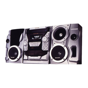
CD-BA1500H Mini Component System consisting of
CD-BA1500H (mani unit) and CP-BA1500H (speaker system).
• In the interests of user-safety the set should be restored to its
original condition and only parts identical to those specified be
used.
This document has been published to be used
for after sales service only.
The contents are subject to change without notice.
CD-BA1500H
No. S3018CDBA1500
Page
Advertisement
Table of Contents

Related Manuals for Sharp CD-BA1500H


Summary of Contents for Sharp CD-BA1500H
-
Page 1: Table Of Contents
No. S3018CDBA1500 CD-BA1500H CD-BA1500H Mini Component System consisting of CD-BA1500H (mani unit) and CP-BA1500H (speaker system). • In the interests of user-safety the set should be restored to its original condition and only parts identical to those specified be used. -
Page 2: Specifications
CD-BA1500H FOR A COMPLETE DESCRIPTION OF THE OPERATION OF THIS UNIT, PLEASE REFER TO THE OPERATION MANUAL. SPECIFICATIONS CD-BA1500H Cassette deck section General Type: Compact cassette tape Power source: AC 230 V, 50 Hz Frequency response: 50 - 14,000 Hz (Normal tape) -
Page 3: Disassembly
CD-BA1500H DISASSEMBLY CD-BA1500H Caution on Disassembly Follow the below-mentioned notes when disassembling Front Panel the unit and reassembling it, to keep it safe and ensure (A1)x2 Top Cabinet excellent performance: ø3x12mm 1. Take cassette tape and compact disc out of the unit. - Page 4 CD-BA1500H Clamp Lever (M2) x1 Turntable Cam Gear Rib Disc Tray (M1) x2 Figure 10-1 CD Player Unit (E1)x2 ø3x10mm Figure 10-4 Front Panel (E5)x1 (E2)x2 (E2)x1 Headphones (N1) x3 (E3)x1 (E2)x1 RDS PWB (E4)x1 Disc Tray (G3)x1 Main PWB ø3x10mm...
- Page 5 CD-BA1500H (R2) x3 Mechanism (R1) x1 (R1) x1 Disc Tray Figure 11-1 CP-BA1500H STEP REMOVAL PROCEDURE FIGURE Woofer 1. Front Panel .... (A1) x1 11-2 2. Screw ..... (A2) x8 11-3 Tweeter 1. Screw ..... (B1) x2 11-3 Speaker Box...
-
Page 6: Removing And Reinstalling The Main Parts
CD-BA1500H REMOVING AND REINSTALLING THE MAIN PARTS TAPE MECHANISM SECTION TAPE2 Perform steps 1 to 5, 8 and 10 of the disassembly method to Record/Playback remove the tape mechanism. Head How to remove the record/playback and erase heads (Tape 2) (See Fig. 12-1) 1. -
Page 7: Adjustment
CD-BA1500H CD MECHANISM SECTION Perform steps 1, 2, 3, 12, 13, 14 and 15 of the disassembly method to remove the CD mechanism. How to remove the T/T Up/Down motor (See Fig. 13-1) T/T Up/Down Motor 1. Bend the hooks (A1) x 5 pcs., to remove the T/T Up/Down motor. -
Page 8: Tuner Section
CD-BA1500H • FM TUNER SECTION Notes: fL: Low-range frequency 1: Description of the "FM IF Adjustment" is not carried on this fH: High-renge frequency Manual. It is because the IF coil in the FM front end section • AM IF/RF... -
Page 9: Test Mode
CD-BA1500H TEST MODE ·Setting the test mode Any one of test mode can be set by pressing several keys as fallows. <X-BASS> + <CD> + <POWER> TEST:CD operation test Function:-CD test mode. -Enter test mode. T E S T IL isn't done OPEN/CLOSE operation is using manual. - Page 10 CD-BA1500H – 16 –...
- Page 11 Preset memory takes priority of switching TN—ON station. Therefore ASPM is usefull not only for PTY search but also for rapid EON switching. Anyway CD-BA1500H EON is basically stand-by and receiving method, along with the Guidelines for EON implementation. – 17 –...
- Page 12 CD-BA1500H EON summary notice for reference 1. EON-TI/PTY EON stand-by can be set, only when EON ind. lights up. While EON ind. goes out (NO EON STATION), EON stand-by can't be set. If the EON button is pressed, then “NO EON” is indication the display.
- Page 13 CD-BA1500H – 19 –...
-
Page 14: Notes On Schematic Diagram
CD-BA1500H NOTES ON SCHEMATIC DIAGRAM • The indicated voltage in each section is the one measured • Resistor: by Digital Multimeter between such a section and the chas- To differentiate the units of resistors, such symbol as K and sis with no signal given. -
Page 15: Block Diagram
CD-BA1500H DISC CLAMP NUMBER OPEN/ M3 T/T CLOSE UP/DOWN MOTOR IC99 TOTX178A OPTICAL FIBER TO MAIN SECTION DATA LINK TO DISPLAY SECTION (TO IC401) 9 10 75 76 45 46 47 48 32 31 30 LC78641E SERVO/SIGNAL CONT5 CONTROL SLD0... - Page 16 CD-BA1500H SO301 ANTENNA TERMINAL +5.1V CF301 Q301 CF302 FE301 FM FRONT END CF351 X351 456KHz AM IF AM LOOP ANT AM IF MO/ST AM MIX IC303 CNP302 LA1832S FM/AM FM/AM IF MPX. MPXIN FM/AM L354 LOW PASS FM OSC L341...
- Page 17 CD-BA1500H R. PLAY F. PLAY FL701 T2 PLAY FL DISPLAY T1 PLAY 21 36 Q604 SOLENOID Q608 MOTOR TAPE DRIVER MOTOR Q601~ Q603 Q607 Q606 LED722 Q605 51 50 44 43 42 44 55 54 53 52 RX701 VLOAD IC701...
- Page 18 CD-BA1500H CD SERVO PWB-B CD SIGNAL Vref TIN1 FIN1 0.047 FIN2 TIN2 LA9235M SERVO AMP. 47/6.3 2.2/50 FIN1 100P ODRV FIN2 RFSW 120K 6.8K AGCON TIN1 (CH) 47/10 0.01 TIN2 100/10 REF1 0.01 0.0047 10/37 VREF 0.33 ODRV RFEV PH/BH...
- Page 19 CD-BA1500H 100P 0.01 100P 100P 100P LC78641E 100P ERVO/SIGNAL 100P CONTROL 100P 2.2µH 0.022 EFMO VDD5V 80 79 78 77 76 75 74 72 71 70 69 68 67 66 65 0.047 PD01 COMMAND GENERAL INTERFACE 1.5M 100/10 PD02 SBCK 2.2/50...
- Page 20 CD-BA1500H C405 0.022 CNS402 R-CH C404 100/16 A_GND P25 12-D L-CH C407 CNP11 CD_GND C406 22/50 10/50 VREF TO CD SERVO C408 10/50 INTERFACE C409 R415 C410 LOUT ROUT 0.1(ML) 0.1(ML) 3.9K C411 0.1(ML) C412 0.1(ML) LBASS RBASS R401 R409 C414 0.0027...
- Page 21 CD-BA1500H DIGITAL OUT PWB-A4 MAIN PWB-A1(1/3) 2.2mH 100/10 0.022 CNP5 TO CD SERVO IC99 P25 12-E TOTX178A BI99 CNS99 OPTICAL FIBER DATA LINK SO401 22/50 VIDEO/AUX 10/50 R419 C429 R421 R416 L-ch 5.6K 390P 3.9K 0.1(ML) R420 C430 5.6K 390P R422 0.0027...
- Page 22 CD-BA1500H IC901 STK40204 POWER AMP. –B C901 C902 470P 220P C903 –B R919 R918 R901 R903 C910 100/50 R916 C906 R906 C905 R931 47/50 47/50 –B C916 R917 R934 (ML) R933 C935 10/50 R907 C915 0.1(1W) R908 D901 0.1(ML) 0.1(1W)
- Page 23 CD-BA1500H R975 CNS971 CNP971 4.7(1/2W) C971 47/50 FM SIGNAL D971 4.9V R971 M901 DS1SS133 FAN MOTOR Q971 KTC3203 Y R973 C972 R972 10/50 RL951 RELAY R953 R954 4.7K 4.7K FW951 C952 220P R952 330(1/2W) L951 2.2mH C951 R951 JK951 D951...
- Page 24 CD-BA1500H MAIN PWB-A1 (3/3) FM SIGNAL AM SIGNAL C302 0.001 T303 C330 C338 0.001 C323 (UJ) 0.022 C331 L354 0.047 C342 R365 TRACKING fL 0.022 C332 R358 0.022 3.9K R350 2.7K D301 C367 AM BAND DS1SS133 1/50 COVERAGE fL VD301...
- Page 25 CD-BA1500H CNP303 RDS PWB-G RT48 LOW PASS FILTER L354 C373 RT49 R363 R364 0.015 C371 R361 1/50 1.2K R350 R362 2.7K C372 1.2K 1/50 C367 LT22 1/50 CT28 2.2µH 17 16 47/10 IC303 LA1832S CT29 CT27 IF DET./FM MPX./AM IF 0.022...
- Page 26 CD-BA1500H DISPLAY PWB-A2 FL701 FL DISPLAY 32 31 Q601 KTC3199 GR Q602 KTC3199 GR Q603 KTC3199 GR -25.7V -25.7V -25.7V C609 C616 1/50 47/50 VLOAD S-BUSY T-BIAS T_T1/T2 REC/PLAY RES OUT RESET R621 P15/DIST0 IC701 P16/DIST1 P17/DIST2 VPP/IC IX0329AW P18/DIST3...
- Page 27 CD-BA1500H 11 10 BI701 CD INT WRQ(DSP) P25 12-F CD CE CD SERVO PWB CD DO CD DI CNP12 CD CLK RES OUT CLAMP SW CNS701 S-BUSY R678 T-BIAS R679 T_T1/T2 R680 REC/PLAY R681 RES OUT R682 R683 FC701 R684...
- Page 28 CD-BA1500H P36 4-G TAPE MECHANISM TO DISPLAY PWB ASSEMBLY CNP702 FC702 TAPE MECHANISM PWB-D TAPE MOTOR SOLENOIDE SOLENOIDE TAPE 2 TAPE 1 RECORD/PLAYBACK ERASE HEAD PLAYBACK HEAD HEAD TO MAIN PWB P35 12-F CNS802 PT801 1 2 3 4 5 6 7 8...
- Page 29 CD-BA1500H POWER PWB-F PT871 SUB POWER TRANSFORMER SO801 L801 AC INPUT SOCKET AC 230V,50 Hz P39 8-F FROM POWER TRANSFORMER CNP801 C873 FW871 Q873 TO MAIN PWB P35 12-E RL871 When Servicing, pay attention as the area enclosed by this line ( ) is directly connected with AC main voltage.
-
Page 30: Voltage
CD-BA1500H VOLTAGE IC101 IC701 IC901 IC303 PIN VOLTAGE NO. VOLTAGE NO. VOLTAGE NO. VOLTAGE NO. VOLTAGE VOLTAGE NO. VOLTAGE 1.6V 0.7V 0V (0V) 5.0V 4.29V 2.1V (2.1V) 1.6V 0V (0V) 4.29V 4.5V (4.8V) 1.6V 0.5V (0.5V) 5.0V 4.29V 2.1V (2.1V) 1.6V... -
Page 31: Waveforms Of Cd Circuit
CD-BA1500H WAVEFORMS OF CD CIRCUIT Stopped Stopped 1999/04/05 17:33:17 CH1=500mV CH3=500mV 500ms/div CH1=500mV CH3=1V CH4=1V 500ms/div DC 10:1 DC 10:1 (500ms/div) DC 10:1 DC 10:1 DC 10:1 (500ms/div) NORM:20kS/s NORM:20kS/s PDO1 IC2 1 IC2 24 PDO2 IC2 2 IC2 23... -
Page 32: Troubleshooting
CD-BA1500H TROUBLE SHOOTING When the CD does not function When the CD section does not operate when the objective lens of the optical pickup is dirty, this section may not operate. Clean the objective lens, and check the playback operation. When this section does not operate even after the above step is taken, check the following items. - Page 33 CD-BA1500H (1) Focus-HF system check Stopped CH1=500mV CH3=500mV 500ms/div Although a CD is inserted and the cover is closed, "NO DC 10:1 DC 10:1 (500ms/div) NORM:20kS/s DISC" is displayed. Press the OPEN/CLOSE switch (SW1) without inserting a disc, and try starting the playback operation.
- Page 34 CD-BA1500H (2) Tracking system check Check the TE waveform at pin 18 on IC1. The tracking servo is not activated. If the waveform shown in Figure 45-1 appears and soon after Check the peripheral circuits at pins 18 and 19 on IC1, pin 23 on NO DISC appears.
- Page 35 CD-BA1500H (4) PLL system check Stopped 1999/04/05 17:33:17 CH1=500mV CH3=1V CH4=1V 500ms/div DC 10:1 DC 10:1 DC 10:1 (500ms/div) NORM:20kS/s When a disc is loaded, start play operation. PDO1 The HF waveform is normal, but the TOC data cannot be PDO2 read.
-
Page 36: Function Table Of Ic
CD-BA1500H FUNCTION TABLE OF IC IC1 VHiLA9235M/-1: Servo Amp. (LA9235M) ODRV FIN1 LA9235M RFSW FIN2 AGCON 28 RF- FIN3 FIN4 26 N/C 25 PH 24 BH REF1 ODRV 23 N/C PH/BH 22 RFEV VREF 21 FE- 20 FE LDOF 19 TE-... - Page 37 CD-BA1500H IC2 VHiLC78641E-1: Servo/Signal Control (LC78641E) (1/2) Terminal Name Input/Output Setting in Reset Function Pin No. PDO1 Output – For PULL Phase-comparison output terminal for built-in VOC control. PDO2 Output – Phase-comparison output terminal for built-in VOC control. Rough servo : OFF, phase servo : ON.
- Page 38 CD-BA1500H IC2 VHiLC78641E-1: Servo/Signal Control (LC78641E) (2/2) Terminal Name Input/Output Setting in Reset Function Pin No. LVDD – – L channel Power terminal for L channel. LCHO Output 1/2VDD D/A converter L channel output terminal. LVSS – – Ground terminal for L channel. Surely connected to 0V.
- Page 39 CD-BA1500H IC701 RH-iX0329AWZZ: System Microcomputer (IX0329AW) (1/2) Pin No. Port Name Terminal Name Input/Output Function — (+) POWER SUPPLY — — S-BUSY Output COMMIJNTCATE TO MPEG U–COM T–BTAS Output TAPE RECORD BIAS T–T1/T2 Output TAPE T1/T2 CHANGE REC/PLAY Output TAPE REC/PLAY CHANGE...
-
Page 40: Fl Display
CD-BA1500H IC701 RH-iX0329AWZZ: System Microcomputer (IX0329AW) (2/2) Pin No. Port Name Terminal Name Input/Output Function P120 PLAY SW_B Input PLAY SWITCH FOR T2 P119 Input TAPE2 A–SIDE FULL PROOF P118 Input TAPE2 B_SIDE FULL PROOF P117 MIC IN Input MIC SWITCH... - Page 41 CD-BA1500H IC401 VHiLC75341/-1: Audio Processor (LC75341) ROUT LOUT LBASS RBASS 0.1uF 0.1uF LTRE RTRE LSEL0 RSEL0 R1 R2 24 23 22 21 20 19 18 17 16 15 14 13 LC75341 10 11 12 Figure 52 BLOCK DIAGRAM OF IC...
- Page 42 CD-BA1500H FL701 VVKBJ749GNK-1: FL Display B7 B6 B5 B4 B3 B4 B5 B6 B7 Figure 53 FL DISPLAY – 53 –...
-
Page 43: Parts Guide
CD-BA1500H PARTS GUIDE CD-BA1500H MODEL CD-BA1500H Mini Component System consisting of CD-BA1500H (main unit) and CP-BA1500H (speaker system). “HOW TO ORDER REPLACEMENT PARTS” To have your order filled promptly and correctly, please furnish the For U.S.A. only following information. Contact your nearest SHARP Parts Distributor to order. - Page 44 CD-BA1500H PRICE PRICE DESCRIPTION PARTS CODE PARTS CODE DESCRIPTION RANK RANK FILTERS CD-BA1500H CF301,302 RFILF0072AFZZ AG FM IF INTEGRATED CIRCUITS CF351 RFILF0003AWZZ AK FM IF CF352 RFILA0009AWZZ AE AM IF VHILA9235M/-1 AQ Servo Amp.,LA9235M TRANSFORMERS VHILC78641E-1 AV Servo/Signal Control,LC78641E VHIM63001FP-1...
- Page 45 CD-BA1500H PRICE PRICE DESCRIPTION PARTS CODE DESCRIPTION PARTS CODE RANK RANK AB 10 µF,50V,Electrolytic C73~78 VCKYTV1HB101K AA 100 pF,50V C407,408 VCEAZA1HW106M J AB 0.1 µF,50V AB 0.1 µF,50V,Mylar VCKYTV1HB104K C409~412 VCQYKA1HM104K J AA 0.022 µF,25V AA 0.0027 µF,16V C81~83 VCKYTV1EF223Z...
- Page 46 CD-BA1500H PRICE PRICE PARTS CODE DESCRIPTION PARTS CODE DESCRIPTION RANK RANK CT26,27 VCCCPA1HH220J AA 22 pF (CH),50V R323 VRD-MN2BD683J AA 68 kohms,1/8W AB 47 µF,10V,Electrolytic CT28 VCEAZA1AW476M J R336 VRD-MN2BD103J AA 10 kohm,1/8W AA 0.022 µF,50V CT29 VCKZPA1HF223Z R344 VRD-MN2BD471J AA 470 ohms,1/8W AA 0.022 µF,50V...
- Page 47 CD-BA1500H PRICE PRICE DESCRIPTION PARTS CODE DESCRIPTION PARTS CODE RANK RANK R642 VRD-MN2BD223J AA 22 kohms,1/8W RT28~30 VRD-ST2CD102J AA 1 kohm,1/6W R643,644 VRD-MN2BD102J AA 1 kohm,1/8W RT32 VRD-ST2CD103J AA 10 kohm,1/6W R645 VRD-MN2BD223J AA 22 kohms,1/8W RT33,34 VRD-ST2CD563J AA 56 kohms,1/6W...
- Page 48 CD-BA1500H PRICE PRICE DESCRIPTION PARTS CODE PARTS CODE DESCRIPTION RANK RANK SW616 QSW-K0009AWZZ J Switch,Key Type [CD] LANGK0192AWFW J AD Bracket,Fan Support SW617 QSW-K0009AWZZ J Switch,Key Type [TAPE] LCHSM0094AWFW J AP Main Chassis SW618 QSW-K0009AWZZ J Switch,Key Type LHLDZ1241AWZZ AE Holder,FL Display...
- Page 49 CD-BA1500H PRICE PRICE DESCRIPTION PARTS CODE DESCRIPTION PARTS CODE RANK RANK QACCB0008AW00 J AW AC Power Supply Cord [For U.K.] QACCE0011AW00 J AM AC Power Supply Cord [For Europe] RRMCG0219AWSA J AR Remote Control GFTAB1022AWSB J AK Battery Lid, Remote Control TINSE0297AWZZ AF Operation Manual [For U.K.]...
- Page 50 CD-BA1500H CD-BA1500H 306-2 306-1 306-3 703x2 305x2 PWB-C Figure 7 CD MECHANISM EXPLODED VIEW – 7 –...
- Page 51 CD-BA1500H CD-BA1500H 604x2 604x2 MECHANISM PWB-E 250x4 239x3 204-2 204-1 204-3 PWB-B Figure 9 CABINET EXPLODED VIEW (2/2) – 9 –...
- Page 52 CD-BA1500H © COPYRIGHT 2000 BY SHARP CORPORATION ALL RIGHTS RESERVED. No part of this publication may be reproduced, stored in a retrieval system, or transmitted in any from or by any means, electronic, mechanical, photocopying, recording, or otherwise, without prior written permission of the publisher.