Table of Contents
Advertisement
Quick Links
SERVICE MANUAL
Ver 1.0 2001.04
9-873-109-11
Sony Corporation
Personal Audio Company
2001D0200-1
Shinagawa Tec Service Manual Production Group
© 2001.4
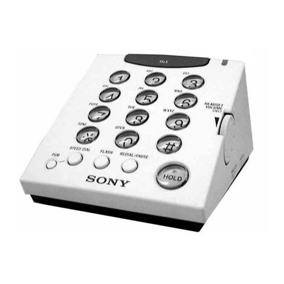
Photo : TL-HP90
SPECIFICATIONS
Dial signal
Dimensions
Mass
Supplied accessories
Headset (TL-DR0140)
Dimension (Cord)
Dimension (Plug)
Mass
<Receiver>
Type
Driver units
Sensitivity
Impedance
Maximum input power
<Microphone>
Type
Unit
Output impedance
Closed circuit voltage level
Design and specifications are subject to change without notice.
TL-HP90
Photo : TL-DR0140
Tone, 10 pps (pulse) selectable
7
1
1
Approx. 3
⁄
X 3
⁄
X 5
⁄
inches (w/h/d)
8
8
2
(98 X 77 X 137.5 mm)
Approx. 9.17 oz
(260 g)
Telephone line code: approx. 7 ft. (2m)
Stereo audio cable (stereo mini-plug):
approx. 3.5 ft. (1m)
Headset TL-DR0140
Headset hanger
Directories
Approx. 7 ft. (2m)
3.5 mm dia.
Approx. 0.88 oz (25 g) (without cord)
Open air dynamic
30 mm dia. (CCAW Voice coil)
104 dB/mW
24
1000 mW (IEC)
Close-talking pipe microphone
Back electret condenser
Under 2.2 k
-47 dB (0 dB = 1 V/Pa)
HANDS FREE TELEPHONE
US Model
Advertisement
Table of Contents

Related Manuals for Sony TL-HP90


Summary of Contents for Sony TL-HP90
- Page 1 TL-HP90 SERVICE MANUAL US Model Ver 1.0 2001.04 Photo : TL-DR0140 Photo : TL-HP90 SPECIFICATIONS Dial signal Tone, 10 pps (pulse) selectable Dimensions Approx. 3 ⁄ ⁄ ⁄ inches (w/h/d) (98 X 77 X 137.5 mm) Mass Approx. 9.17 oz...
-
Page 2: Table Of Contents
TL-HP90 SECTION 1 GENERAL TABLE OF CONTENTS Specifications ................1 This section is extracted from instruction manual. 1. GENERAL ..............2 2. DISASSEMBLY Identifying the part 2-1. Case (Upper) , Case (Lower) ........5 2-2. Main Board ..............5 Lamp 2-3. -
Page 3: Choose The Dialing Mode
TL-HP90 Listening to music, etc. from an external equipment Choose the dialing mode If you want to listen to music, etc. from the external equipment, you can do For the phone to work properly, select an appropriate dialing mode (tone or it using the headset during TALK off status. -
Page 4: Speed Dialing
TL-HP90 Speed dialing You can dial with a touch of a few buttons by storing a phone number on a dialing button. You can store up to 10 different phone numbers. Storing phone numbers Press (TALK). The lamp lights up. -
Page 5: Disassembly
TL-HP90 SECTION 2 DISASSEMBLY Note : Follow the disassembly procedure in the numerical order given. Case (upper) Volume board, key board Main board Case (lower) 2-1. CASE (UPPER), CASE (LOWER) Case (upper) 3 Connector (4 pin) (CN301) 4 Connector (14 pin) -
Page 6: Volume Board, Key Board
TL-HP90 2-3. VOLUME BOARD, KEY BOARD 4 Screws (+BTP2.6X8) 2 Screws (+BTP2.6X8) Key board Volume board Case (upper) Knob (VOL) -
Page 7: Diagrams
TL-HP90 SECTION 3 DIAGRAMS 3-1. BLOCK DIAGRAMS • Signal path. : RX : TX : bell... -
Page 8: Schematic Diagram
TL-HP90 3-2. SCHEMATIC DIAGRAM Refer to page 10 for Notes. Refer to page 10 for Waveforms. Refer to page 11, 12 for IC Block Diagrams. -
Page 9: Printed Wiring Boards - Main Section
TL-HP90 3-3. PRINTED WIRING BOARDS – MAIN SECTION – MJ101 MJ102 J601 TEL/DATA LINE MAIN BOARD (SIDE-B) AUDIO IN MAIN BOARD (SIDE-A) CN301 KEY BOARD S301 J101 R601 S301 DIAL MODE HEADSET D201 C121 D108 R311 D203 D202 R602 F101... -
Page 10: Printed Wiring Boards - Key Section
TL-HP90 3-4. PRINTED WIRING BOARDS – KEY SECTION – Note on Schematic Diagram: MAIN SECTION • All capacitors are in µF unless otherwise noted. pF: µµF 50 WV or less are not indicated except for electrolytics KEY BOARD and tantalums. -
Page 11: Ic Block Diagrams
TL-HP90 • IC BLOCK DIAGRAMS IC101 TEA1112AT/C1.518 MIC+ MIC- CIRCUIT CURRENT REFERENCE VOLTAGE CIRCUIT MICRO MUTE DRIVER SLPE MMUTE OTMF MUTE IC201 DBL5002 IC102 NJM2149V-TE2 HFO GND HIGH LOW OSC POWER SUPPLY... - Page 12 TL-HP90 IC301 HM91652B 21 20 19 18 ROW/COLUMN PULSE DECODER & PROGRAMMING GENERATOR DATA LATCH CONVERTER COUNTER SAVE MEMORY MEMORY MEMORY OUTPUT INPUT KERNEL CONTROL CIRCUIT INTERFACE INTERFACE CIRCUIT CIRCUIT COLUMN DIVIDER INTERFACE INTERFACE CIRCUIT CIRCUIT 2 3 4 5...
-
Page 13: Exploded Views
TL-HP90 SECTION 4 EXPLODED VIEWS NOTE : • -XX, -X mean standardized parts, so they • The mechanical parts with no reference may have some difference from the original number in the exploded views are not one. supplied. • Items marked “ * ”are not stocked since they •... -
Page 14: Electrical Parts List
TL-HP90 SECTION 5 MAIN ELECTRICAL PARTS LIST NOTE : • Due to standardization, replacements in the • SEMICONDUCTORS When indicating parts by reference num- In each case, u : µ , for example : parts list may be different from the parts ber, please include the board. - Page 15 TL-HP90 MAIN Ref. No. Part No. Description Remark Ref. No. Part No. Description Remark <CONNECTOR> <JACK> CN101 1-564-705-11 PIN, CONNECTOR (SMALL TYPE) 3P J101 1-785-368-11 JACK (HEADSET) CN201 1-564-704-11 PIN, CONNECTOR (SMALL TYPE) 2P J601 1-566-822-21 JACK (AUDIO IN) CN301...
-
Page 16: Key Volume
TL-HP90 KEY VOLUME MAIN Ref. No. Part No. Description Remark Ref. No. Part No. Description Remark R162 1-216-831-11 METAL CHIP 6.8K 1/16W R601 1-216-797-11 METAL CHIP 1/16W R163 1-216-831-11 METAL CHIP 6.8K 1/16W R602 1-216-797-11 METAL CHIP 1/16W R165 1-216-853-11 METAL CHIP... - Page 17 TL-HP90...
- Page 18 TL-HP90 REVISION HISTORY Clicking the version allows you to jump to the revised page. Also, clicking the version at the upper right on the revised page allows you to jump to the next revised page. Ver. Date Description of Revision...