Table of Contents
Advertisement
SERVICE MANUAL
Dolby noise reduction and HX Pro headroom ex-
tension manufactured under license from Dolby
Laboratories Licensing Corporation. HX Pro origi-
nated by Bang & Olufsen.
"DOLBY", the double-D symbol a, and "HX PRO"
are trademarks of Dolby Laboratories Licensing Cor-
poration.
MICROFILM
TC-KB820S
Model Name Using Similar Mechanism
Tape Transport Mechanism Type
SPECIFICATIONS
STEREO CASSETTE DECK
AEP Model
UK Model
Australian Model
TC-KE400S
TCM-190VB12CSS
– Continued on next page –
Advertisement
Table of Contents

Related Manuals for Sony TC-KB820S


Summary of Contents for Sony TC-KB820S
- Page 1 TC-KB820S SERVICE MANUAL AEP Model UK Model Australian Model Dolby noise reduction and HX Pro headroom ex- Model Name Using Similar Mechanism TC-KE400S tension manufactured under license from Dolby Tape Transport Mechanism Type TCM-190VB12CSS Laboratories Licensing Corporation. HX Pro origi- nated by Bang &...
- Page 2 LINE WITH MARK ! ON THE SCHEMATIC DIAGRAMS AND IN THE PARTS LIST ARE CRITICAL TO SAFE OPERATION. REPLACE THESE COMPONENTS WITH SONY PARTS WHOSE PART NUMBERS APPEAR AS SHOWN IN THIS MANUAL OR IN SUPPLEMENTS PUB- LISHED BY SONY.
-
Page 3: Table Of Contents
TABLE OF CONTENTS GENERAL ..............4 DISASSEMBLY ............5 MECHANICAL ADJUSTMENTS ....... 9 ELECTRICAL ADJUSTMENTS ......10 DIAGRAMS 5-1. Note for Printed Wiring Boards and Schematic Diagrams ............14 5-2. Printed Wiring Boards – MD Section – ......15 5-3. Schematic Diagram – MD Section – ......17 5-4. -
Page 4: General
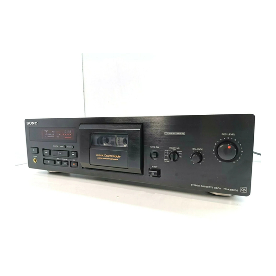
SECTION 1 GENERAL LOCATION OF CONTROLS 1 I/O (Power) button 8 Cassette holder 2 Remote control sensor 9 § EJECT button 3 PHONES jack !º AUTO CAL button 4 Display panel !¡ DOLBY NR switch 5 Tape operation buttons !™ BALANCE control !£... -
Page 5: Disassembly
SECTION 2 DISASSEMBLY Note: Follow the disassembly procedure in the numerical order given. CASE Unscrew the four case attachment seven tapping screws and remove the case. FRONT PANEL SECTION 1 flat cable (CN801) 3 screw 2 connector (BVTP3 × 8) (CN506) 1 flat cable (CN81) - Page 6 MAIN BOARD 4 two screws (BVTP3 × 8) 1 connector (CN701) 5 MAIN board 2 screw (BV/ring) 4 screw (BV/ring) 3 bracket (TR) CASSETTE HOLDER (R) ASS’Y 4 cassette holder (R) ass’y 2 boss 1 torsion spring 3 shaft – 6 –...
- Page 7 FITTING BASE BLOCK 2 two screws (PTPWH2 × 23) 1 connector (CNP32) 2 screw (PTPWH2 × 23) 3 fitting base block Note: When installing, pull the FR belt and put around the claws as shown below. Note: When installing, pull the capstan belt and put around the claws as shown below.
- Page 8 MOTOR 2 flexible board (CNP72) 1 connector (CNP71) 6 capstan motor !º ground plate 4 audio 3 claw 5 two screws board (B2.6 × 3) 8 reel motor 3 claw 9 FR belt 3 two claws 7 two screws (P2.6 × 2.8) –...
-
Page 9: Mechanical Adjustments
SECTION 3 MECHANICAL ADJUSTMENTS PRECAUTION 1. Clean the following parts with a denatured alcohol-moistened swab: record/playback/erase head pinch roller rubber belts capstan idler 2. Demagnetize the record/playback head with a head demagne- tizer. (Head demagnetizer do not approach for the erase head.) 3. -
Page 10: Electrical Adjustments
SECTION 4 ELECTRICAL ADJUSTMENTS Note: The adjustment should be performed in the order given in the ser- Record/Playback Head Azimuth Adjustment vice manual. As a rule, adjustments about playback should be per- Procedure: formed before those about recording. 1. Mode : FWD playback The adjustments should be performed before for both L-CH and R- Test tape •... - Page 11 Tape Speed Adjustment Procedure: Bias Consumption Current Adjustment Mode: playback Procedure: LINE IN test tape (no signal) WS-48B digital voltmeter CS-413 blank tape frequency counter (3 kHz, 0 dB) 47 k Ω – – TP81 LINE OUT 3 2 1 1.
- Page 12 Adjustment Location: [MAIN BOARD] –COMPONENT SIDE – Record Level Adjustment Setting: REC LEVEL control: Standard Record (See page 10.) CN831 CN833 DOLBY-S Procedure: BOARD 1. Mode: record LINE IN 315 Hz, 0.5 V (–3.8 dB) AF OSC CS-123 blank tape 10 k Ω...
-
Page 13: Diagrams
SECTION 5 DIAGRAMS • Circuit Boards Location 5-1. NOTE FOR PRINTED WIRING BOARDS AND SCHEMATIC DIAGRAMS (In addition to this, the necessary note is each block.) Note on Schematic Diagram: Note on Printed Wiring Boards: • All capacitors are in µF unless otherwise noted. pF: µµF •... -
Page 14: Printed Wiring Boards – Md Section
TC-KB820S 5-2. PRINTED WIRING BOARDS – MD Section – • See page 13 for Circuit Boards Location. (Page 20) (Page 19) (Page 19) • Semiconductor Location Ref. No. Location IC31 IC81 •IC81 (Note) •:LEAF SW BOARD – 15 – – 16 –... -
Page 15: Schematic Diagram - Md Section
TC-KB820S 5-3. SCHEMATIC DIAGRAM – MD Section – • See page 27 for Waveforms. (Page 21) (Page 21) (Page 23) – 17 – – 18 –... -
Page 16: Printed Wiring Board – Main Section
TC-KB820S 5-4. PRINTED WIRING BOARD – MAIN Section – • See page 13 for Circuit Boards Location. • Semiconductor (Page 32) (Page 15) (Page 15) (Page 31) (Page 31) (Page 15) Location Ref. No. Location D131 D132 D231 D232 D511... -
Page 17: Schematic Diagram - Main Section - (1/3)
TC-KB820S 5-5. SCHEMATIC DIAGRAM – MAIN Section – (1/3) (Page 30) (Page 23) (Page 34) (Page 18) (Page 18) (Page 30) (Page 23) The components identified by mark ! or dotted line with mark ! are critical for safety. Replace only with part number specified. -
Page 18: Schematic Diagram - Main Section - (2/3)
TC-KB820S 5-6. SCHEMATIC DIAGRAM – MAIN Section – (2/3) • See page 27 for Waveforms. (Page 22) (Page 25) (Page 25) (Page 22) (Page 18) – 23 – – 24 –... -
Page 19: Schematic Diagram - Main Section - (3/3)
TC-KB820S 5-7. SCHEMATIC DIAGRAM – MAIN Section – (3/3) • See page 28 for IC Block Diagrams. (Page 34) (Page 24) (Page 33) (Page 33) (Page 24) The components identified by mark ! or dotted line with mark ! are critical for safety. - Page 20 • Waveforms • IC Block Diagrams – AUDIO BOARD – IC1 CXA1917AM-T6 (DOLBY-S BOARD) 1 T51 1 6 IC81 !¡, !™ ANTSAT 118 Vp-p 6.2 Vp-p SLDET SLICG FLVCR SLVCR V TO I FLDET FLICG CONV H 9.3 µ s 9.3 µ...
-
Page 21: Printed Wiring Board - Dolby-S Section
TC-KB820S 5-8. PRINTED WIRING BOARD – DOLBY-S Section – 5-9. SCHEMATIC DIAGRAM – DOLBY-S Section – • See page 13 for Circuit Boards Location. • See page 28 for IC Block Diagrams. (Page 21) (Page 20) – 29 – – 30 –... -
Page 22: Printed Wiring Boards - Panel Section
TC-KB820S 5-10. PRINTED WIRING BOARDS – PANEL Section – • See page 13 for Circuit Boards Location. (Page 19) (Page 19) (Page 32) (Page 32) (Page 20) (Page 19) – 31 – – 32 –... -
Page 23: Schematic Diagram - Panel Section
TC-KB820S 5-11. SCHEMATIC DIAGRAM – PANEL Section – (Page 26) (Page 21) (Page 26) (Page 26) The components identified by mark ! or dotted line with mark ! are critical for safety. Replace only with part number specified. – 33 –... -
Page 24: Ic Pin Function Description
5-12. IC PIN FUNCTION DESCRIPTION • MAIN BOARD IC801 CXP82612-022Q (SYSTEM CONTROLLER) Pin No. Pin Name Function Pin No. Pin Name Function STOP SW Mechanism stop detect switch (S81) input terminal Recording/playback control signal output to the CXA1563S (IC501) REC/PB “L”: recording mode, “H”: playback mode SIRCS IN Sircs signal input from the remote control receiver (IC901) -
Page 25: Exploded Views
SECTION 6 EXPLODED VIEWS NOTE: • -XX and -X mean standardized parts, so they • Items marked “*” are not stocked since they The components identified by mark ! or dotted line with mark may have some difference from the original are seldom required for routine service. - Page 26 1-696-456-11 WIRE (FLAT TYPE) (31 CORE) 3-020-979-01 KNOB (BALANCE) 1-590-486-11 WIRE (FLAT TYPE) (7 CORE) X-3374-953-1 LID ASSY, CASSETTE 3-020-975-01 BUTTON (CONTROL) 4-942-568-41 EMBLEM (NO.5), SONY 3-020-977-01 BUTTON (AUTO CAL) 3-020-971-01 PANEL, FRONT (AEP,UK) 3-933-299-01 KNOB (DIA. 12) 3-020-971-21 PANEL, FRONT (Australian)
- Page 27 (13) MD ASS’Y SECTION TCM-190VB12CSS Ref. No. Part No. Description Remark Ref. No. Part No. Description Remark X-3368-119-1 HOLDER (R) ASSY, CASSETTE * 105 3-354-954-01 LEVER (LOCK LEVER R) 3-354-963-01 DAMPER 3-354-962-01 SPRING (EJ SAFTY SPRING R) 1-769-914-11 WIRE (FLAT TYPE) (9 CORE) 3-354-956-01 LEVER (EJ SAFTY LEVER R) 3-354-957-01 JOINT (LOCK LEVER) 3-354-960-01 SPRING (LOADING R), TORSION...
- Page 28 (4) MECHANISM DECK SECTION-1 (TCM-190VB12CSS) M902 supplied supplied M901 HE901 supplied supplied not supplied Ref. No. Part No. Description Remark Ref. No. Part No. Description Remark 3-907-362-01 SPRING, TORSION * 164 1-638-020-11 LEAF SW BOARD A-2004-673-A DECK (ONE) ASSY, HEAD (including HRP901) 3-359-430-01 SPRING (CASSETTE RETAINER), LEAF 3-343-484-01 SPRING, COMPRESSION 3-575-321-00 RETAINER, THRUST, CAPSTAN...
- Page 29 (5) MECHANISM DECK SECTION-2 (TCM-190VB12CSS) Ref. No. Part No. Description Remark Ref. No. Part No. Description Remark 3-359-469-01 SPACER 3-359-419-11 GEAR (FR GEAR) X-3359-416-1 CHASSIS ASSY, MECHANICAL 3-359-421-01 CLUTCH (REEL DISK) * 203 3-359-415-01 SLIDER (TRIGGER SLIDER) 3-359-418-01 PULLEY (FR PULLEY) 3-359-454-01 SPRING, TORSION 3-924-185-11 SPRING (FR ARM), TORSION 3-359-429-01 SLIDER (BRAKE PLATE)
-
Page 30: Electrical Parts List
AC POWER SW SECTION 7 AUDIO ELECTRICAL PARTS LIST NOTE: • Due to standardization, replacements in the • Items marked “*” are not stocked since they The components identified by mark ! or dotted line with mark are seldom required for routine service. parts list may be different from the parts speci- ! are critical for safety. - Page 31 AUDIO DOLBY-S Ref. No. Part No. Description Remark Ref. No. Part No. Description Remark 1-216-025-00 RES, CHIP 1/10W 1-136-165-00 FILM 0.1uF 1-216-100-00 RES, CHIP 130K 1/10W 1-137-372-11 FILM 0.022uF 1-216-068-00 METAL CHIP 6.2K 1/10W 1-164-222-11 CERAMIC CHIP 0.22uF 1-216-033-00 METAL CHIP 1/10W 1-126-301-11 ELECT 1-216-033-00 METAL CHIP...
- Page 32 LEAF SW MAIN Ref. No. Part No. Description Remark Ref. No. Part No. Description Remark HP BOARD C116 1-136-170-00 FILM 0.27uF C131 1-126-963-11 ELECT 4.7uF ********* (Included in MAIN BOARD, COMPLETE) C132 1-126-962-11 ELECT 3.3uF C201 1-137-372-11 FILM 0.022uF < CAPACITOR > C202 1-126-963-11 ELECT 4.7uF...
- Page 33 MAIN Ref. No. Part No. Description Remark Ref. No. Part No. Description Remark C810 1-162-282-31 CERAMIC 100PF IC801 8-752-856-27 IC CXP82612-022Q C811 1-164-159-11 CERAMIC 0.1uF IC802 8-759-165-82 IC PST600E-T C812 1-137-374-11 FILM 0.047uF < JACK > < CONNECTOR > J501 1-784-430-11 JACK, PIN 4P (LINE IN, OUT) * CN81 1-568-826-11 SOCKET, CONNECTOR 7P...
- Page 34 MAIN Ref. No. Part No. Description Remark Ref. No. Part No. Description Remark R123 1-249-421-11 CARBON 2.2K 1/4W R517 1-249-433-11 CARBON 1/4W R124 1-249-437-11 CARBON 1/4W R125 1-249-425-11 CARBON 4.7K 1/4W R518 1-249-425-11 CARBON 4.7K 1/4W R131 1-249-425-11 CARBON 4.7K 1/4W R521 1-249-426-11 CARBON...
- Page 35 MAIN PANEL REC VOL Ref. No. Part No. Description Remark Ref. No. Part No. Description Remark R709 1-249-409-11 CARBON 1/4W R710 1-249-417-11 CARBON 1/4W < CONNECTOR > R711 1-249-427-11 CARBON 6.8K 1/4W R712 1-249-427-11 CARBON 6.8K 1/4W * CN901 1-568-845-11 SOCKET, CONNECTOR 31P R713 1-249-421-11 CARBON 2.2K...
- Page 36 TC-KB820S TRANSFORMER Ref. No. Part No. Description Remark Ref. No. Part No. Description Remark TRANSFORMER BOARD ******************* (Included in MAIN BOARD, COMPLETE) 3-923-762-11 HOLDER (TR) < CAPACITOR > C712 1-161-494-00 CERAMIC 0.022uF C714 1-136-169-00 FILM 0.22uF C715 1-136-169-00 FILM 0.22uF <...