Pioneer DJM-2000 Service Manual
Hide thumbs
Also See for DJM-2000:
- Operating instructions manual (204 pages) ,
- Manual de usuario (32 pages) ,
- Firmware update manual (31 pages)
Table of Contents
Advertisement
Quick Links
DJ MIXER
DJM-2000
THIS MANUAL IS APPLICABLE TO THE FOLLOWING MODEL(S) AND TYPE(S).
Model
Type
DJM-2000
SYXJ8
DJM-2000
CUXJ
DJM-2000
LXJ
DJM-2000
KXJ5
DJM-2000
AXJ5
For details, refer to "Important Check Points for good servicing".
PIONEER CORPORATION
PIONEER ELECTRONICS (USA) INC. P.O. Box 1760, Long Beach, CA 90801-1760, U.S.A.
PIONEER EUROPE NV Haven 1087, Keetberglaan 1, 9120 Melsele, Belgium
PIONEER ELECTRONICS ASIACENTRE PTE. LTD. 253 Alexandra Road, #04-01, Singapore 159936
PIONEER CORPORATION
Power Requirement
AC 220 V to 240 V
AC 120 V
AC 110 V to 240 V
AC 220 V
AC 220 V to 240 V
1-1, Shin-ogura, Saiwai-ku, Kawasaki-shi, Kanagawa 212-0031, Japan
2010
DJM-2000
K-IZV MAY
ORDER NO.
RRV4046
Remarks
2010 Printed in Japan
Advertisement
Table of Contents

Related Manuals for Pioneer DJM-2000


Summary of Contents for Pioneer DJM-2000
- Page 1 PIONEER CORPORATION 1-1, Shin-ogura, Saiwai-ku, Kawasaki-shi, Kanagawa 212-0031, Japan PIONEER ELECTRONICS (USA) INC. P.O. Box 1760, Long Beach, CA 90801-1760, U.S.A. PIONEER EUROPE NV Haven 1087, Keetberglaan 1, 9120 Melsele, Belgium PIONEER ELECTRONICS ASIACENTRE PTE. LTD. 253 Alexandra Road, #04-01, Singapore 159936...
-
Page 2: Safety Information
PIONEER Service Manual. A subscription to, or additional copies of, Also test with plug reversed Earth PIONEER Service Manual may be obtained at a nominal (Using AC adapter ground charge from PIONEER. plug as required) - Page 3 To protect products from damages or failures during transit, the shipping mode should be set or the shipping screws should be installed before shipment. Please be sure to follow this method especially if it is specified in this manual. DJM-2000...
-
Page 4: Table Of Contents
10.16 HAMP (1/2) and HREG ASSYS ..........................114 10.17 HAMP (2/2) and HPJK ASSYS ..........................116 10.18 AOUT ASSY (1/4) ..............................118 10.19 AOUT ASSY (2/4) ..............................124 10.20 AOUT ASSY (3/4) ..............................126 10.21 AOUT ASSY (4/4) ..............................128 10.22 PNLE (1/2), CFD1, CFD2 and CRFD ASSYS......................130 DJM-2000... - Page 5 11.8 PNLE, CFD1, CFD2 and CRFD ASSYS........................198 11.9 PNCE ASSY ................................202 11.10 PNRI, CFD3 and CFD4 ASSYS ..........................206 11.11 TFTB ASSY ................................210 11.12 TPRI and TPLE ASSYS............................212 11.13 POWER SUPPLY and ACSW ASSYS ........................214 12. PCB PARTS LIST ................................215 DJM-2000...
-
Page 6: Service Precautions
(3) Do not put one touch panel on the other. Otherwise, it may cause the touch panel to be scratched and/or change on cosmetic occur (e.g. Newton ring). (4) Do not put a heavy, hard or sharp object on the touch panel. DJM-2000... -
Page 7: Specifications
Channel equalizer characteristic HI............–26 dB to +6 dB (13 kHz) MID............–26 dB to +6 dB (1 kHz) LOW............–26 dB to +6 dB (70 Hz) Microphone equalizer characteristic HI............–12 dB to +12 dB (10 kHz) LOW............–12 dB to +12 dB (100 Hz) DJM-2000... -
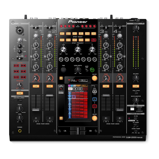
Page 8: Panel Facilities
2.2 PANEL FACILITIES Control Panel DJM-2000... - Page 9 Rear Panel DJM-2000...
-
Page 10: Basic Items For Service
No scratches or dirt on its appearance after receiving it for Check the appearance of the product. service. See the table below for the items to be checked regarding audio. Item to be checked regarding audio Distortion Noise Volume too low Volume too high Volume fluctuating Sound interrupted DJM-2000... -
Page 11: Pcb Locations
HPJK ASSY HREG ASSY Control Panel Section • Bottom view PNCE ASSY PNLE ASSY TFTB ASSY PNRI ASSY CRFD ASSY TPRI ASSY TPLE ASSY • Bottom view LCD & Touch Panel CFD1 CFD2 CFD3 CFD4 ASSY ASSY ASSY ASSY DJM-2000... - Page 12 DWX3010 2..CFD3 ASSY DWX2932 2..TPRI ASSY DWX3011 2..CFD4 ASSY DWX2933 1..OUHP ASSY DWM2336 1..MAIN ASSY DWX2920 2..HAMP ASSY DWX2919 > 2..AOUT ASSY DWX2924 1..POWER SUPPLY ASSY DWR1473 or DWR1492 2..HPJK ASSY DWX2939 2..HREG ASSY DWX2940 CWX3868 Touch Panel DSX1081 DJM-2000...
- Page 13 DJM-2000...
-
Page 14: Block Diagram
The > mark found on some component parts indicates the importance of the safety factor of the part. DKN1281- Therefore, when replacing, be sure to use parts of identical designation. PHONES : The power supply is shown with the marked box. DJM-2000... -
Page 15: Power Supply
CN1002 CN5601 VKN1416-A VKN1416-A (TOP) (TOP) CPU_MUTE HP_DATA RESET GNDD LRCK1 GNDD BCK1 GNDD D20PYY0605E MCLK1 GNDD VADET GNDD HREG ASSY (DWX2940) HP_R PF04PP-D20 GNDHP 4P PH L=225mm GNDHP HP_L JA6001 CN6001 DKN1281- KM200NA4L (SIDE) PHONES HPJK ASSY (DWX2939) DJM-2000... -
Page 16: Block Diagram
STBY CONTROL CS5381-KZ NJM4580MD PHONO CH4 R IC3904 IC3900 IC3906 NJM4580MD NJM4580MD RESET AIN2 ASSY IC5404 IC5402 RETURN RNB4580F BUFFER AK5358AET RETURN CH1-4 DIGI/ANA SW RETURN IN MASTER AOUT ASSY AIN1 ASSY INFORMATION TRIM_VR AIN2 ASSY : Parallel signal DJM-2000... - Page 17 RGB 6bit STBY CONTROL STANDBY MATRIX MATRIX RESET MAIN_CPU Multi INPUT STANDBY (uCOM A) Plexer SELECT Touch BACKLIGHT IC1105 Panel CONTROL IC uPD78K0R1164 CWX3868 DSX1081 IC2601 FADER TK61222CQ6 PNLE ASSY EFFECT ON/OFF TFTB ASSY PNRI ASSY Multi TRIM_VR Plexer DJM-2000...
-
Page 18: Dsp Block Diagram
4.3 DSP BLOCK DIAGRAM DJM-2000... - Page 19 DJM-2000...
-
Page 20: Power Block Diagram
ASSY CFD3 CFD4 TPRI ASSY ASSY ASSY V+3R3D GNDD MAIN ASSY TFTB ASSY V+12D GNDD_BLP V+2R5D V+3R3D IC1002 V+3R3E V+12E IC1001 BACKLIGHT TOUCH PANEL V+1R2D V+12D IC1005 GNDREF V+3R3REF V+3R3D V+12D IC1003 GNDD V+3R3D V+5D V+12D IC1004 V+5D V+12E DJM-2000... - Page 21 AIN1 ASSY ASSY V+3R3REF AIN2 ASSY AOUT ASSY GNDREF V+3R3D -15VA GNDA +5VA +15VA HAMP ASSY POWER V+7E_UN V+7E_UN SUPPLY GNDD GNDD ASSY V+12V V+12V V+12E V+12A +15VA V+12E IC103 +15VA +9VA IC105 -9VA -15VA IC104 HPJK ASSY HREG ASSY DJM-2000...
-
Page 22: Diagnosis
Canceling reset of SRC (CH4) by setting Pin G4 to H. USB_SBY "L" Reception of acknowledgement of USB startup completion, by setting Pin 40 to L. After USB initial settings are completed, USB data input to Pin 42 (I) and initialization USB data output from Pin 43 (O) start. DJM-2000... - Page 23 After USB initial settings are completed, USB data input to Pin 42 (I) and initialization USB data output from Pin 43 (O) start. Switching lines Power-on muting duration elapses Canceling reset Canceling muting by setting Pin 73 to L. DJM-2000...
-
Page 24: Error Indications
Software reset completion is V+1R5D_PSB, V+5D and V+3R2D_REG. LINK(PC1) on the LCD display. time-out • Check 25 MHz clock is oscillated. → PCIF Assy No. 10, 11 * No. of the PCB Assy are referred to section "10.30 WAVEFORMS." DJM-2000... - Page 25 Please update it again. Update Error E006 DSP data Please update it again. Update Error E007 Please update it again. Update Error E008 Update file error Please update it again. Update Error EE00 - EE64 Network error Please update it again. DJM-2000...
-
Page 26: Voltage Monitoring Circuit
V+5D < 4.2V > 5.77V V+3R3D < 2.8V > 3.8V When an error is generated V+1R2D < 1.08V < 1.08V > 1.32V > 1.32V V+15A < 14.1V > 15.9V V-15A < -16.8V > -13.2V V+5A < 4.4V > 5.6V DJM-2000... -
Page 27: Connection Check With Each Interface
Devices to be added: • Universal Serial Bus controllers USB Composite Device • Under “Sound, video and game controllers” PIONEER DJM-2000 USB Audio Device A communication check may be easily performed if connection is made with Device Manager displayed on the PC screen. -
Page 28: Service Mode
MONO SPLIT STEREO MIXING MIDI REMIX ON /OFF START/STOP SNAPSHOT MASTER CURVE SETTING LEVEL ON/OFF CH EQ ISOLATOR THRU THRU THRU THRU CH FADER CROSS FADER ASSIGN CROSS FADER ASSIGN PHONES PROFESSIONAL MIXER CROSS FADER DJM-2000 Test Mode: CANCEL POWER DJM-2000... - Page 29 Confirmation of defective pixels (green) on the main panel. SUB PANEL TEST Confirmation of defective pixels (green) on the subpanel. MAIN PANEL TEST Confirmation of defective pixels (blue) on the main panel. SUB PANEL TEST Confirmation of defective pixels (blue) on the subpanel. DJM-2000...
- Page 30 Touch Panel IC is displayed: OK: Communication established, NG: Communication not established LAN: The communication status between each LAN port and the connected device is displayed. For details on usage, see “5.4 CONNECTION CHECK WITH EACH INTERFACE.” DJM-2000...
- Page 31 Page 04 : Key Test (1) Page 06 : Key Test (3) Page 05 : Key Test (2) Page 07 : Switch Test (1) DJM-2000...
- Page 32 Page 11 : Volume Test (3) The corresponding level meters shown below will light in response to controlling the following variable registers on Pages 09–12: Level meters CH1 fader CH2 fader CH3 fader CH4 fader BALANCE MASTER L BOOTH MONITOR MASTER R DJM-2000...
- Page 33 At first, all the LEDs are unlit. If the CUE key is pressed after it was pressed 15 times (when the top LED is lit), all the LEDs become unlit again. Then the same steps can be repeated. DJM-2000...
- Page 34 Page 16 : Main Panel Test Page 18 : Main Panel Test Color bar White Page 17 : Sub Panel Test Page 19 : Sub Panel Test White Color bar DJM-2000...
- Page 35 Page 20 : Main Panel Test Page 22 : Main Panel Test Black Page 21 : Sub Panel Test Page 23 : Sub Panel Test Black DJM-2000...
- Page 36 Page 24 : Main Panel Test Page 26 : Main Panel Test Green Blue Page 27 : Sub Panel Test Page 25 : Sub Panel Test Green Blue DJM-2000...
-
Page 37: C 7. Disassembly
White White Gray Black Black Gray White Knob (RES) Rotary Knob (BN) Knob (FREQUENCY) Rotary SW Knob (C) (DAA1250) ×5 (DAA1220) ×6 (DAA1253) ×3 (DAA1180) White Black White Black White Black Black White Slider Knob (DAC2501) ×5 White Black DJM-2000... - Page 38 Rotary SW knob S (B) Rotary SW knob S (C) (6) Remove the rotary SW knob S (B). (7) Remove the two screws. (BPZ30P100FTB) ×2 (8) Remove the eight screws. (CCZ30P080FTB) Rotary SW knob S (C) ×4 ×2 ×4 DJM-2000...
- Page 39 Style the cables so that they will not protrude outside. CRFD Assy Connector Assy (3P) During reassembly, align the pin Control panel section Main unit on the control panel with the hole of the main unit for proper alignment. Main unit Hole DJM-2000...
- Page 40 (2) Remove the seven screws. (BPZ30P080FTB) ×2 ×2 2 2 2 • Rear view (3) Remove the screw. (BBZ30P060FTC) Barrier (W) (4) Lift up the barrier (W) to a front direction. TRIM stay (5) Remove the nine screws. (BBZ30P060FTC) Input stay DJM-2000...
- Page 41 (6) Lift up the AIN1 and AIN2 Assemblies to a front direction. AIN1 Assy AIN2 Assy Diagnosis Barrier (W) Control panel section PNCE Assy AIN1 Assy PCIF Assy PNRI Assy AIN2 Assy AOUT Assy PNLE Assy MAIN Assy POWER SUPPLY HAMP Assy Assy DJM-2000...
- Page 42 Control panel L (3) Remove the Control panel L, R, CHF panel ×3 and CRF panel. ×2 (4) Remove the CRF stay with CRFD Assy. ×3 CHF panel ×2 ×2 CRF stay Control panel R CRF panel CHF panel CRFD Assy DJM-2000...
- Page 43 Light shield A ×2 Bush ×2 SW packing ×2 Light shield A (4) Remove the two screws. (PMA20P040FTC) (5) Remove the CFD2 Assy. ×2 (6) Disconnect the flexible cable. (7) Remove the six screws. (BBZ30P060FTC) CFD2 Assy CN7503 ×6 LCD section DJM-2000...
- Page 44 (3) Remove the LCD stay with TFTB Assy. (4) Remove the LCD. CN2403 (5) Remove the protect plate and touch panel CN2404 spacer. CN2601 (6) Remove the touch panel. LCD stay Protect plate Touch panel spacer Touch panel • Bottom view DJM-2000...
-
Page 45: Each Setting And Adjustment
3. Disconnect the PC from the network then connect it with the DJM-2000. Note: Directly connect the PC and DJM-2000, using a LAN cable. Either a straight or cross LAN cable can be used. 4. Start up the DJM-2000 in Update mode. - Page 46 7. A standby screen for connection with the DJM-2000 will be displayed. *It may take 1 minute or longer before connection is established. 8. After connection is successfully established, updating of the firmware of the DJM-2000 will be executed automatically. DJM-2000...
- Page 47 In a case of the Auto IP setting in a Windows environment, it may take 1 minute or longer until the network communication is established after the DJM-2000 is connected with the PC. In such a case, the current status can be confirmed on the Windows PC.
-
Page 48: Work Required After The Eeprom Is Replaced
Preconditions All the PC boards must be connected properly to the unit. Connect the PC and the DJM-2000 via LAN then start up the application for updating in the same manner as in a case of usual updating. k Operation Start up Checker mode of the main unit by setting the POWER switch to ON while holding the INST FX NOISE, LINK CUE, and CH2 CUE buttons pressed. -
Page 49: Calibration Adjustment
[The display returns to [Touch panel confirmation screen 1].] Press the SAVE Detection of or CANCEL touching button. Touching of the 5 points is finished. [TCH FX ON/OFF] SAVE CANCEL Calibration Start SAVE: For storing data CANCEL: For abandoning data DJM-2000... -
Page 50: User Setable Items
AUTO STANDBY ON/OFF CLUB OUTPUT TO BOOTH ON/OFF SETUP MONITOR TALK OVER THRESHOLD -25 dB, -20 dB, -15 dB, -10 dB LEVEL TALK OVER LEVEL -25 dB, -20 dB, -15 dB, -10 dB TOUCH PANEL Set it individually. DJM-2000... -
Page 51: Sheet For Confirmation Of The User Setting
TALK OVER THRESHOLD LEVEL -25 dB -20 dB -15 dB -10 dB TALK OVER LEVEL -25 dB -20 dB -15 dB -10 dB TOUCH PANEL Perform calibration. FACTORY RESET NEVER perform FACTORY RESET before taking note of setting data. DJM-2000... -
Page 52: Exploded Views And Parts List
Screws adjacent to b mark on product are used for disassembly. For the applying amount of lubricants or glue, follow the instructions in this manual. (In the case of no amount instructions, apply as you think it appropriate.) 9.1 PACKING SECTION SYXJ8, CUXJ types only KXJ5 type only ×4 DJM-2000... - Page 53 16 Pad R (DJM-2000) DHA1786 17 Packing Case See Contrast table (2) NSP 18 Flyer See Contrast table (2) (2) CONTRAST TABLE DJM-2000/SYXJ8, CUXJ, LXJ, KXJ5 and AXJ5 are constructed the same except for the following: DJM-2000 DJM-2000 DJM-2000 DJM-2000 DJM-2000 Mark...
-
Page 54: Exterior Section
9.2 EXTERIOR SECTION CUXJ only Refer to “9.4 CONTROL PANEL SECTION”. CUXJ CUXJ, LXJ, KXJ5 only only Refer to “9.3 BOTTOM SECTION”. CUXJ only CUXJ only DJM-2000... - Page 55 23 Side Panel L DNK5363 24 Side Panel R DNK5364 25 Extension Shaft A DNK5365 (2) CONTRAST TABLE DJM-2000/SYXJ8, CUXJ, LXJ, KXJ5 and AXJ5 are constructed the same except for the following: DJM-2000 DJM-2000 DJM-2000 DJM-2000 DJM-2000 Mark Symbol and Description...
-
Page 56: Bottom Section
9.3 BOTTOM SECTION PNLE CN7509 TFTB CN2401 TFTB CN2402 AIN1 CN4302 AIN1 HREG HPJK CN4303 CN110 CN6001 AIN1 CN4301 AIN2 CN4201 CUXJ only DJM-2000... - Page 57 DNF1815 23 AC Shield DNF1816 24 Earth Plate DNF1858 25 Power Knob Guard DNK4534 (2) CONTRAST TABLE DJM-2000/SYXJ8, CUXJ, LXJ, KXJ5 and AXJ5 are constructed the same except for the following: DJM-2000 DJM-2000 DJM-2000 DJM-2000 DJM-2000 Mark Symbol and Description...
-
Page 58: Control Panel Section
9.4 CONTROL PANEL SECTION Refer to “9.5 LCD SECTION”. Light shield A Holder A Light shield A MAIN MAIN CN1605 CN1602 MAIN CN1101 DJM-2000... - Page 59 DNF1812 37 CRF Stay DNF1855 38 Lens DNK4532 39 Lens Holder DNK4533 40 Bush DNK5367 41 Light Shield DNK5583 42 Level Meter Assy DXB1882 43 Binder ZCA-SKB90BK 44 • • • • • 45 • • • • • DJM-2000...
-
Page 60: Lcd Section
Center panel (No. 29). Center panel DELAY FILTER ECHO • Rear view PNLE CN7503 MAIN CN1602 MAIN CN1605 DJM-2000... - Page 61 26 Touch Panel Pad DEC3168 27 Touch Panel Spacer DEC3269 28 LCD Stay DNF1818 29 Center Panel DNK5370 30 Cord Clamper (Steel) RNH-184 31 • • • • • 32 • • • • • 33 Screw BBZ30P060FTC 34 Screw BPZ30P080FTB DJM-2000...
-
Page 62: Schematic Diagram
1 2 I 2 S / L J R 3 0 4 8 1 0 k R 3 0 4 9 C S 5 3 8 1 - K Z CH1_ADAT 4:15F 1 0 0 GNDD R 3 0 5 5 (C1D) DJM-2000... - Page 63 R 3 0 6 2 C S 5 3 8 1 - K Z PHONO / LINE GNDA V-15A 1 0 k CH1_ADAT 4:15F 1 0 0 C H 1 _ A D A T R 3 0 5 5 (C1D) DJM-2000...
-
Page 64: Ain1 Assy (2/5)
R 3 3 5 5 GNDA GNDD (C2D) 4:15G CFTLA F A D E R _ S T O P 2 CH2_ADAT Q 3 3 0 9 CEANP R T 1 N 2 4 1 M CEHAZL GNDA GNDA GNDA DJM-2000... - Page 65 C S 5 3 8 1 - K Z 3 4 9 1 0 k GNDA GNDD GNDA C H 2 _ A D A T CD / LINE 1 0 0 V-15A 4:15G R 3 3 5 5 (C2D) CH2_ADAT DJM-2000...
-
Page 66: Ain1 (3/5) And Mcjk Assys
U D Z S 1 5 ( B ) U D Z S 1 5 ( B ) GNDA NOTES is STBY U D Z S 1 5 ( B ) U D Z S 1 5 ( B ) DKB1108-A CCSRCH CFTLA RN1/16SE****D DJM-2000... - Page 67 M I C _ D A T A (MICD) MIC_DATA MIC_ADC NOTES is STBY RS1/10SR***J RN1/16SE****D CKSRYB CCSRCH CFTLA CEAT CEJQ JQNP CEJQNP MIC AMP Audio Signal Route (MIC) : MIC Signal (L CH) (MICD) : MIC Data Signal DJM-2000...
-
Page 68: Ain1 Assy (4/5)
R 4 3 2 3 V C C 2 . 2 k C 4 3 2 3 CH4_SPDIF 4 7 p / 5 0 (D4) (D4) G N D GNDD R 4 3 1 9 TC7WU04FU 1 0 0 GNDD GNDD GNDD GNDD DJM-2000... - Page 69 R 4 9 4 2 IC4319 GNDD R 4 9 4 3 V C C I N B I N A (D4) R 4 3 7 5 O U T Y G N D GNDA GNDD TC7SH08FUS1 GNDD DIGITAL IN DJM-2000...
-
Page 70: Ain1 (5/5), Trim1 And Trim2 Assys
V R 2 2 2 1 V R 2 2 4 1 D C S 1 1 0 3 - A D C S 1 1 0 3 - A C 2 2 4 1 C 2 2 2 1 0.1u 0.1u CN3000 CN3300 DJM-2000... -
Page 71: Trim3, Trim4 And Ain2 (1/3) Assys
C 4 2 0 8 GNDA 0.1u GNDREF 0.1u 0.1u V+15A V+3R3D GNDA V-15A GNDA C 4 2 0 9 V+12A V-15A 0.1u V+12A GNDA V+12A C 4 2 1 1 4 7 u / 2 5 GNDD E F G DJM-2000... -
Page 72: Ain2 Assy (2/3)
R 3 6 1 9 CCSRCH R 3 6 5 5 CFTLA CH3_A F A D E R _ S T O P 3 Q 3 6 0 9 CEANP R T 1 N 2 4 1 M CEHAZL GNDA GNDA GNDA DJM-2000... - Page 73 C S 5 3 8 1 - K Z R 3 6 4 9 1 0 k GNDA GNDD GNDA (C3D) INPUT CH3 V-15A 1 0 0 C H 3 _ A D A T R 3 6 5 5 CD / LINE CH3_ADAT DJM-2000...
-
Page 74: Ain2 Assy (3/3)
1 0 k 1 2 I 2 S / L J R 3 9 4 9 1 0 k C S 5 3 8 1 - K Z GNDD (C4D) 1 0 0 R 3 9 5 5 CH4_ADAT DJM-2000... - Page 75 R 3 9 6 2 INPUT CH4 C S 5 3 8 1 - K Z V-15A GNDA 1 0 k PHONO / CD (C4D) 1 0 0 C H 4 _ A D A T R 3 9 5 5 CH4_ADAT DJM-2000...
-
Page 76: Pcif Assy
RXP6 0.1u F 2 0 1 5 R 2 0 8 4 4 9 . 9 STBY R 2 0 8 5 4 9 . 9 RXN6 C 2 1 6 4 R 2 1 1 1 STBY GNDD DJM-2000... - Page 77 G N D D he part. STBY R 2 1 3 7 Q2002 USB/LAN/MIDI UM6K1N 6 D1 R 2 1 5 3 R 2 1 5 2 5 G2 4 S2 STBY R 2 1 3 3 STBY GNDD DJM-2000...
- Page 78 DJM-2000...
- Page 79 DJM-2000...
- Page 80 DJM-2000...
- Page 81 DJM-2000...
-
Page 82: Main Assy (1/6)
G N D D G N D D G N D D I N A R 1 1 8 3 20MHz G N D O U T Y S H _ R E S E T 4:11L;4:14H;4:9B TC7SH08FUS1 G N D D DJM-2000... - Page 83 2 4 M _ C L K _ F P G A R 1 1 2 9 G N D D G N D D 24MHz 4 : 1 1 C 2 4 M _ C L K _ S H R 1 1 3 0 DJM-2000...
- Page 84 DJM-2000...
- Page 85 DJM-2000...
- Page 86 DJM-2000...
- Page 87 DJM-2000...
-
Page 88: Main Assy (2/6)
X H R D Y 3:2B STBY V+3R3D STBY NOTES is STBY RS1/10SR***J-T RS1/8SQ***J-T RS1/16SS***J-T Q 1 3 0 1 R T 1 N 2 4 1 M CKSSYB 4:2E D S P 1 _ C T R L CCSSCH GNDD CEVW*** DJM-2000... - Page 89 R 1 4 1 6 2 2 DSP1_ADRS_A0 DSP1_ADRS_A3 FDSP_ADRS_A3 DSP1_ADRS_A1 1 2 0 MX29LV400CTTI-70G-K R 1 2 4 0 DSP1_ADRS_A4 FDSP_ADRS_A4 GNDD DYW1789- /J DSP1_ADRS_A5 FDSP_ADRS_A5 DSP1_ADRS_A6 FDSP_ADRS_A6 DSP1_ADRS_A7 FDSP_ADRS_A7 1 2 0 R 1 2 4 6 DSP1_CLK_BUS FDSP_CLK 1:9B DSP1_BUS MAIN DSP1 DJM-2000...
- Page 90 DJM-2000...
- Page 91 DJM-2000...
- Page 92 DJM-2000...
- Page 93 DJM-2000...
-
Page 94: Main Assy (3/6)
A D A T _ B O O T H (RECD) 1:6E CEVW*** A D A T _ R E C (SENDD) A D A T _ S E N D 1 : 6 E (HPD) A D A T _ H P 6 : 3 F DJM-2000... - Page 95 G N D D C 1 5 0 5 STBY 0 . 1 u C 1 5 0 6 0 . 1 u G N D D Audio Signal Route : Audio Data Signal MAIN DSP2 : Digital Audio Data Signal DJM-2000...
- Page 96 DJM-2000...
- Page 97 DJM-2000...
- Page 98 DJM-2000...
- Page 99 DJM-2000...
-
Page 100: Main Assy (4/6)
R 1 6 5 3 5:13D O U T Y G N D L A N O U T S U B I C _ R E S E T G N D TC7SH08FUS1 1/6,5/6,6/6 G N D D 1:5B;1:6D;5:11E;5:11G;5:13K;5:4D;5:4F;5:4I;5:4K;6:3F DJM-2000... - Page 101 G N D D STBY USB CLOCK R E S E T CONNECTOR MODE7 G N D D S H _ R E S E T EXT CLOCK R 1 7 3 1 SYSTEM CLOCK MODE8 EXT CLOCK G N D D DJM-2000...
- Page 102 DJM-2000...
- Page 103 DJM-2000...
- Page 104 DJM-2000...
- Page 105 DJM-2000...
-
Page 106: Main Assy (5/6)
9 6 k _ C L K _ R 2 1 3 8 R 1 8 8 6 G N D O U T Y G N D O U T Y TC7SH08FUS1 TC7SH08FUS1 G N D D G N D D DJM-2000... -
Page 107: Usb Out
1:8D;7A I N B V C C 9 6 k _ C L K _ M A I N I N A R 1 9 0 3 G N D O U T Y G N D D TC7SH08FUS1 DJM-2000... - Page 108 DJM-2000...
- Page 109 DJM-2000...
- Page 110 DJM-2000...
- Page 111 DJM-2000...
-
Page 112: Main Assy (6/6)
V N F 1 1 0 9 V N F 1 1 0 9 V N F 1 1 0 9 V N F 1 1 0 9 CKSRYB CKSQYB CCSRCH The > m CCSSCH indicates CEVW*** Therefore of identic G N D D DJM-2000... - Page 113 G N D BD9326EFJ The > mark found on some component parts indicates the importance of the safety factor of the part. Therefore, when replacing, be sure to use parts of identical designation. STBY G N D D MAIN POWER DJM-2000...
-
Page 114: Hamp (1/2) And Hreg Assys
A E K 7 0 0 3 - A 315mA C N 1 0 2 STBY K M 2 0 0 N A 8 R 5 7 8 8 +12V STBY +12V Switched +12V Switched GNDD GNDD STBY Control RESET V+7E_UN GNDD DJM-2000... - Page 115 R B 5 0 1 V - 4 0 3 IN +9VA RESET V+7E_UN GNDHP K N 1 0 3 K N 1 0 4 V N F 1 0 8 4 V N F 1 0 8 4 CKSRYB GNDA DJM-2000...
-
Page 116: Hamp (2/2) And Hpjk Assys
K N 1 0 2 RS1/10SR****D V N F 1 0 8 4 V N F 1 0 8 4 RD1/2VM***J CKSRYB CKSYB V-15A CCSRCH CEHAZL GNDHP Audio Signal Route (HP) : HEADPHONE Signal (L CH) (HPD) : HEADPHONE Data Signal NOTE DJM-2000... - Page 117 C N 6 0 0 1 KM200NA4L JA6001 R 6 0 0 5 DKN1281-A (HP) HP_L PHONES GNDHP R 6 0 0 6 GNDHP HP_R STBY STBY STBY CFTLA103J50-TD NOTES is STBY R 6 0 0 7 GNDF GNDF CKSRYB CFTLA GNDHP RS1/10SR***J DJM-2000...
-
Page 118: Aout Assy (1/4)
Q 5 5 0 9 R 5 5 9 8 R T 1 N 2 4 1 M 5 1 k Q 5 5 1 0 2SC4154(EFG) R 5 6 1 9 5 1 k CPU_MUTE GNDA GNDD GNDA GNDA V-15A DJM-2000... - Page 119 M A S T E R 2 _ R - GNDA RS1/16S****D RD1/4MUF***J RD1/2VM***J RN1/16SE****D V-15AICP CKSRYB STBY CCSRCH CCSQCH GNDD CEAT CEANP CEHAT CEHAZL Audio Signal Route (M1) : MASTER1 Signal (L CH) (M2) MASTER1 OUT : MASTER2 Signal (L CH) (M1D) : MASTER1 Data Signal DJM-2000...
- Page 120 DJM-2000...
- Page 121 DJM-2000...
- Page 122 DJM-2000...
- Page 123 DJM-2000...
-
Page 124: Aout Assy (2/4)
1 0 u / 5 0 V-15A GNDA GNDA GNDD GNDA GNDA GNDA C 5 2 4 2 1 0 u / 5 0 NOTES is STBY 1/4,3/4,4/4 RS1/10SR***J RS1/16S****D M U T E 1:4L;7C;7D;3:4D;4:3G RD1/2VM***J RN1/16SE****D CKSRYB CCSRCH CCSQCH CEAT CEANP DJM-2000... - Page 125 I N C 2 0 0 2 A C 1 R 5 2 4 2 RNB4580F 1 8 k GNDA GNDA GNDA GNDA GNDA Audio Signal Route (M2) : MASTER2 Signal (L CH) (REC) : REC Signal (L CH) MASTER2 / REC (RECD) : REC Data Signal DJM-2000...
-
Page 126: Aout Assy (3/4)
DKN1452-A 1 0 u / 5 0 I C 5 4 0 2 1 0 0 3 6 k RNB4580F-TBB STBY V-15A C 5 4 1 4 V+3R3D GNDA 1:3H R E T U R N _ I N DJM-2000... - Page 127 0 . 1 u / 2 5 RETURN_ADC 80F-TBB GNDA GNDA GNDD GNDA GNDA Audio Signal Route (SEND) : SEND Signal (L CH) (RET) : RETURN Signal (L CH) SEND/RETURN (SENDD) : SEND Data Signal (RETD) : RETURN Data Signal DJM-2000...
-
Page 128: Aout Assy (4/4)
C 5 5 1 7 V-15A C 5 5 2 2 0.1u I C 5 5 0 2 100p NJM4565MD C 5 5 1 8 1 0 0 u / 2 5 GNDA 1/4-3/4 M U T E 1:4L;2:5G;2:7C;2:7D;3:4D DJM-2000... - Page 129 0.1u 1 8 k 1 8 k V-15A GNDA R 5 5 3 5 DCE1016-A 2 2 k GNDA C 5 5 2 8 100p Audio Signal Route BOOTH : BOOTH Signal (L CH) (BD) : BOOTH Data Signal DJM-2000...
-
Page 130: Pnle (1/2), Cfd1, Cfd2 And Crfd Assys
1 S S 3 5 5 KEY_GRID2 LED_SEG14 LED_SEG14 NOTES is STBY LED_SEG13 LED_SEG13 LED_GRID7A RS1/10SR***J LED_GRID7A LED_SEG8A LED_SEG8A CKSRYB E F 1 _ S W EF1_SW CEAT E F 2 _ S W EF2_SW LED_GRID0A LED_GRID0A CEJQ KEY_GRID5 KEY_GRID5 DJM-2000... - Page 131 R E S E T D 7 5 7 0 uCOMB_RESET 1 S S 3 5 5 20MHz E F 2 _ S W EF_SW2 E F 1 _ S W EF_SW1 GNDD V+3R3D V+5D GNDD GNDD V+5D V+12E V+5D GNDD V+12E GNDD DJM-2000...
- Page 132 DJM-2000...
- Page 133 DJM-2000...
- Page 134 DJM-2000...
- Page 135 DJM-2000...
-
Page 136: Pnle Assy (2/2)
D 7 5 5 3 NOTES is STBY RS1/10SR***J 1 S S 3 5 5 CKSRYB D 7 5 5 6 D 7 5 5 4 1 S S 3 5 5 DSK1026-A DSK1026-A KEY_SEG1 MIC SELECT IN1 SELECT CD/PHONO/USB DJM-2000... - Page 137 G N D TC74HC4052AF PARAMETER GNDREF_B GNDREF_B V+3R3REF_B VRSEL_1_0 VRSEL_1_1 C 7 5 4 5 V R 7 5 4 3 VR_IN5 D C S 1 1 0 0 - A 0 . 1 u / 2 5 GNDREF_B GNDREF_B GNDD DJM-2000...
-
Page 138: Pnce Assy
CEAT R 7 0 6 3 2 S C 4 1 5 4 ( E F G ) Q 7 0 1 6 CEJQ LED_SEG7 R 7 2 5 0 R 7 2 6 6 GNDD LED_GRID0A LED_GRID5A LED_GRID6A DJM-2000... - Page 139 V R _ C H 4 _ C O L O R V R _ C H 3 _ C O L O R I N H GNDREF_B GNDD V E E G N D TC74HC4052AF GNDREF_B GNDREF_B GNDREF_B DJM-2000...
- Page 140 DJM-2000...
- Page 141 DJM-2000...
- Page 142 DJM-2000...
- Page 143 DJM-2000...
-
Page 144: Pnri, Cfd3 And Cfd4 Assys
D 7 8 1 0 R 7 8 1 9 R 7 8 3 2 STBY KEY_SEG8 GNDD D 7 8 1 1 R 7 8 0 9 LED_SEG2A LED_GRID0A 1 2 0 SLR343WBD2PT(Z1)-TS R 7 8 1 0 MIDI ON/OFF STBY DJM-2000... - Page 145 1 S S 3 5 5 1 S S 3 5 5 S7810 DSH1066-A D 7 8 1 9 D 7 8 1 7 D 7 8 1 5 D 7 8 2 1 NOTES is STBY RS1/10SR***J CKSRYB CEJQ DJM-2000...
-
Page 146: Tftb Assy
V N F 1 0 8 4 V N F 1 0 8 4 V N F 1 0 8 4 R 2 4 4 1 R 2 4 4 2 R 2 4 4 3 GNDD GNDD GNDD GNDD GNDD GND_BLP DJM-2000... - Page 147 TEST3 The > mark found on some component parts indicates the importance of the safety factor of the part. NOTES is STBY Therefore, when replacing, be sure to use parts of identical designation. RS1/10SR***J-T CKSRYB CEVW TFT LCD/TOUCH PANEL DJM-2000...
-
Page 148: Tpri And Tple Assys
D 8 1 2 0 GNDD R 8 1 1 7 R 8 1 3 9 S M L - 0 1 2 W T ( U V W X Y ) R 8 1 4 0 D 8 1 2 9 DJM-2000... - Page 149 D 8 1 2 8 D 8 1 1 1 D 8 1 1 6 D 8 1 2 0 M L - 0 1 2 W T ( U V W X Y ) EFFECT ON/OFF 2 D 8 1 2 9 DJM-2000...
-
Page 150: Power Supply And Acsw Assys
ACSW ASSY (DWX2918) DSA1036-A STBY C N 1 2 - 1 7 8 4 9 6 - 4 DKP3799-A LIVE (WHITE) A C G 7 0 3 0 - A INLET NEUTRAL (BROWN) COVER FOR "C1":DEC3212- • NOTE CAUT DJM-2000... - Page 151 Therefore, when replacing, be sure to use parts of identical designation. • NOTE FOR FUSE REPLACEMENT CAUTION - FOR CONTINUED PROTECTION AGAINST RISK OF FIRE, REPLACE WITH SAME TYPE AND RATINGS OF FUSE. DJM-2000...
-
Page 152: Voltages
PARAMETER CENTER CH SELECT EFFECT SELECT DELAY EFFECT FREQUENCY ALL CENTER BEAT EFFECT BEAT BUTTONS 1/1(BLINKING) LEVEL/DEPTH CENTER ON/OFF OFF(LIGTING) MIDI TOUCH PANEL EFFECT REMIX ON/OFF DISPLAY DEFAULT CUE BUTTONS ALL OFF MIDI ON/OFF CLUB SET UP Factory setting DJM-2000... - Page 153 0.00 MCLKI 0.00 P1.4/MCUAD4 0.01 RSTO# 3.40 MCLKI2 0.00 P1.5/MCUAD5 0.03 P3.0/MCUA8 3.17 AVSS 0.00 P1.6/MCUAD6 3.40 P3.1/MCUA9 3.39 XTALO 1.54 P1.7/MCUAD7 3.40 DVSS2 0.00 XTALI 1.59 DVSS3 0.00 XINT# 3.41 PLLFILI 0.01 CSCLK 0.00 P3.3/MCUA10 3.40 CSYNC 0.00 DJM-2000...
- Page 154 IC1001 (BA338C0WFP) 3.38 VCC3O2 3.21 VREF 1.21 12V → 3.3V(EuP) Pin Name Pin No. Voltage[V] 11.98 11.98 0.00 3.30 0.00 IC1004 (BD9326EFJ) 12V → 5V Pin No. Voltage[V] Pin Name 10.63 11.93 5.08 0.00 0.90 COMP 1.16 4.98 2.46 DJM-2000...
- Page 155 0.00 1.76 3.42 3.42 3.42 3.42 3.42 3.42 SAOF 0.00 SAOF 0.00 SAOF 0.00 0.00 0.91 3.42 SAIF 0.00 SAIF 0.00 SAIF 0.00 1.20 3.41 0.00 SRC_UNLOCK 3.41 SRC_UNLOCK 0.00 SRC_UNLOCK 0.00 2.58 3.42 1.20 2.55 1.72 2.56 1.73 DJM-2000...
- Page 156 3.42 0.00 3.31 0.00 CKSEL 0.00 CKSEL 0.00 1.21 3.31 0.00 3.41 3.31 1.22 0.34 3.31 3.42 3.13 1.22 0.00 3.37 0.00 1.80 3.42 3.41 3.42 0.00 0.00 3.42 1.22 3.41 0.00 3.36 3.42 1.22 3.36 0.42 3.36 0.01 DJM-2000...
- Page 157 0.01 0.01 0.00 VDDQ4 3.42 VDDQ4 3.42 VDDQ4 3.42 DQ13 3.41 DQ13 3.31 DQ13 0.01 DQ14 3.35 DQ14 3.29 DQ14 0.01 VSSQ4 0.00 VSSQ4 0.00 VSSQ4 0.00 DQ15 3.34-3.36 DQ15 3.29 DQ15 0.00 VSS3 0.00 VSS3 0.00 VSS3 0.00 DJM-2000...
- Page 158 0.00 0.01 3.42 2.01 0.00 3.42 1.75 3.10 0.122-0.268 0.01 0.00 3.42 0.08 2.62 1.80 3.42 2.93 0.01 0.83 1.29 2.56 1.28 0.00 0.00 1.29 0.06 2.49 0.00 3.42 3.42 0.440-0.450 2.483-2.515 1.23 0.00 1.26 0.00 3.34 0.00 0.00 DJM-2000...
- Page 159 3.42 3.10 0.00 0.00 3.40 3.40 3.42 3.11 0.00 3.40 3.42 3.42 3.12 0.00 3.40 3.32 3.13 12.20 0.00 3.40 3.38 0.00 0.00 0.00 3.40 2.30 1.78 0.00 0.00 3.40 0.00 1.71 0.00 0.00 3.40 0.00 3.42 0.848-0.861 0.00 DJM-2000...
- Page 160 0.08 0.00 0.01 0.00 0.00 0.24-0.32 0.00 0.00 1.71 0.00 0.01 0.00 2.16 0.07 0.00 0.05-0.13 1.61 0.00 2.46 0.00 0.06-0.13 2.52 3.39 0.00 3.42 0.24-0.40 3.37 0.09 0.00 1.64 3.30 1.23 0.94 3.30 0.00 0.01 0.00 3.27 3.30 DJM-2000...
- Page 161 0.02 SDATA 1.65-1.80 AOUTR 2.46 AOUTR 2.45 0.02 LRCK 1.71 AOUTL 2.46 AOUTL 2.45 1.70 VCOM 2.45 VCOM 2.44 1.70 0.00 0.00 1.68 AVDD 4.91 AVDD 4.92 1.68 DVDD 4.87 DVDD 4.87 X-COM 1.67 0.00 0.00 1.67 1.66 3.32 DJM-2000...
- Page 162 0.00 LED3 0.00 0.00 LED2 0.00 0.17 LED1 2.06 0.00 EAOUT 0.00 0.79-0.86 ISET 0.52 -0.01 0.00 0.21 PGND 0.00 0.00 1.20 0.18 0.44 0.60 0.67 0.00 0.87 0.00 0.34 0.57 0.80 0.00 0.90 0.00 0.00 DCLK 1.62 0.00 DJM-2000...
-
Page 163: Waveforms
V: 0.5 V/div. H: 200 μS/div. C4937_TP (LINE1_L) IC3004 - pin 1_TP-R3040 R4952_TP (CD2_L) CN3300 - pin 5_TP V: 0.5 V/div. H: 200 μS/div. V: 0.2 V/div. H: 200 μS/div. V: 0.5 V/div. H: 200 μS/div. V: 0.2 V/div. H: 200 μS/div. DJM-2000... - Page 164 V: 0.5 V/div. H: 500 μS/div. V: 0.2 V/div. H: 200 μS/div. CN3600 - pin 5 C4226 - pin 2 (C4226-R4210) IC3904 - pin 1_TP-R3940 V: 0.2 V/div. H: 200 μS/div. V: 0.5 V/div. H: 200 μS/div. V: 0.2 V/div. H: 200 μS/div. DJM-2000...
- Page 165 V: 2 V/div. H: 5 mS/div. CN2001 - pin 11_TP R2082 IC2009 - pin 6_TP R2077 V: 2 V/div. H: 1 μS/div. V: 1 V/div. H: 2 μS/div. V: 1 V/div. H: 1 μS/div. V: 1 V/div. H: 1 μS/div. DJM-2000...
- Page 166 C5618 - R5736_(R5736) CN5602_pin 1 V: 0.2 V/div. H: 200 μS/div. V: 0.2 V/div. H: 200 μS/div. TFTB ASSY CN2601 - pin 4_TP (LED1) CN2601 - pin 6 (ANODE2) V: 2 V/div. H: 1 mS/div. V: 5 V/div. H: 5 mS/div. DJM-2000...
- Page 167 V: 2 V/div. H: 1 μS/div. V: 2 V/div. H: 5 mS/div. CN1101_pin 15_TP CN1104_pin 9_TP CN1105_pin 16_TP R1138 V: 2 V/div. H: 5 μS/div. V: 2 V/div. H: 1 μS/div. V: 2 V/div. H: 1 μS/div. V: 0.5 V/div. H: 1 mS/div. DJM-2000...
- Page 168 V: 1 V/div. H: 5 mS/div. V: 1 V/div. H: 5 mS/div. R1145 CN1601_pin 13_TP CN1605_pin 12_TP R1867 V: 2 V/div. H: 1 μS/div. V: 1 V/div. H: 200 μS/div. V: 1 V/div. H: 2 μS/div. V: 1 V/div. H: 20 nS/div. DJM-2000...
- Page 169 IC1910 - pin 9 (Thru hole) CN1002_pin 11 (Thru hole) V: 2 V/div. H: 2 μS/div. V: 2 V/div. H: 500 nS/div. IC1908 - pin 9 CN1002_pin 12 (Thru hole) V: 2 V/div. H: 5 μS/div. V: 1 V/div. H: 5 mS/div. DJM-2000...
- Page 170 DJM-2000...
-
Page 171: Pcb Connection Diagram
Connector Capacitor 1. The parts mounted on this PCB include all necessary parts for several destinations. SIDE A For further information for respective desti- nations, be sure to check with the sche- matic diagram. SIDE B P.C.Board Chip Part DJM-2000... -
Page 172: Ain1 Assy
R4375 1.V+5D IC4314 IC4316 R4373 2.MIC_DATA V+3R3D IC4315 R4941 3.DIGIANA_SW1 V+5D 4.LINE_SEL1 R4942 5.CH1_ADAT R4943 16.FADER_START2 CN4302 6.RESET 17.LINE_SEL2 13.GNDD C4367 C4365 18.CH2_ADAT 7.GNDD 10.BCLK C4366 14.DIGIANA_SW2 11.GNDD 19.V+3R3D 8.MCLK 9.GNDD 12.LRCK 15.FADER_STOP2 20.GNDD CONTACT UPPER SIDE CN4302 CN1106 DJM-2000... - Page 173 R3364 BCLK34 11.CH1_SPDIF CH2_ADAT 22.LINE_SEL4 R3363 MCLK34 R3349 12.CH2_SPDIF R4375 23.CH4_ADAT R4373 R3348 CN4303 1.V+5A R3347 V+3R3REF 2.GNDA 3.V+15A C4378 CN4301 4.GNDA C4367 5.V-15A C4365 C4366 CONTACT 6.GNDA UPPER SIDE 7.V+12A ACT UPPER SIDE CN4303 CN4301 (DNP2438-A) CN1104 CN104 DJM-2000...
- Page 174 SIDE B Q3320 Q3319 IC3006 AIN1 ASSY CD2_L LINE2_L LINE2_R CD2_R Q3319 C3366 CN4301 CN4303 DJM-2000...
- Page 175 SIDE B NOTE: The encircled numbers denote measuring point. Q3320 Q3016 Q3319 Q3015 IC3006 IC3007 AIN1 DWX2922- CD2_L CD2_R Q3319 C3366 R3109 CN4302 (DNP2438-A) DJM-2000...
-
Page 176: Mcjk, Trim1 - Trim4 Assys
TRIM2 ASSY [[ G ]] DWX2936 TRM2 A30C5/C7 CN2241 VR2241 VR2221 CN2221 CN2241 (DNP2438-A) (DNP2438-A) CN3000 CN3300 TRIM3 ASSY TRIM4 ASSY [[ G ]] TRM3 DXW2937 A30C5/C7 CN2261 VR2261 CN2261 CN2281 (DNP2606-A) (DNP2606-A) CN3600 CN3900 B C D E F DJM-2000... - Page 177 SIDE B SIDE B MCJK ASSY DWX2934- MCJK R2202 C2204 R2201 C2203 (DNP2441-A) CN2200 TRIM2 ASSY TRIM1 ASSY DWX2936 TRM2 CN2241 CN2221 (DNP2438-A) (DNP2438-A) TRIM4 ASSY TRIM3 ASSY CN2281 CN2261 (DNP2606-A) (DNP2606-A) B C D E F DJM-2000...
-
Page 178: Ain2 Assy
D3904 D3903 R3991 IC3906 R3985 D3902 IC3905 R4001 C3964 R3983 R3997 R3987 R4000 R4006 R4004 R3996 C3962 R3980 R3979 R3988 R3994 C3969 C3967 R3984 R3992 R3976 CN3900 CN2281 IC3602 IC3902 IC3605 IC3603 Q3615-3618 Q3911-3914 IC3903 IC3604 IC3904 IC3906 IC3905 DJM-2000... - Page 179 L INE4_R C3931 R3934 Q3907 R3927 C3934 PHONO4_R R4010 R4210 C4217 R4211 C3911 CN3900 C4219 C4226 C3912 C4220 5/C7 C3926 C4227 C4218 C3909 JA3900 CN3900 (DNP2606-A) CN2281 IC3600 Q3600-3609 Q3614 IC3601 3618 Q3910 Q3613 Q3611 Q3612 Q3610 IC3901 Q3900-3909 IC3900 DJM-2000...
- Page 180 C3602 R3602 R3637 C3608 R3615 R3639 R3629 R3636 R3621 C3609 R3603 C3604 Q3916 C3900 R3960 R3973 R3974 R3914 C3939 C3903 R4008 R3902 C3907 C3908 R3903 C3904 AIN2 C3901 R3915 DWX2923- R3900 R4009 C3905 C3906 R3901 C3902 CN3900 Q3620 Q3916 DJM-2000...
- Page 181 C3660 R3672 C3665 C3666 C3638 C3657 C3658 C3960 C3961 Q3916 Q3915 3960 R3661 3973 C3970 3974 7.V+12A R4013 R3968 6.GNDA 5.V+15A C3971 4.GNDA C4207 C3939 C3958 3.V-15A 2.GNDA C3959 1.V+5A C4209 CN3900 (DNP2606-A) Q3620 Q3619 IC3606 Q3916 Q3915 IC3907 DJM-2000...
-
Page 182: Pcif Assy
R2147 IC2008 12.RxD2 11.RxD3 R2169 C2078 10.GNDD 9.RX_CLK R217 8.GNDD Q2006 R2179 7.TX_CLK 6.GNDD R2177 5.TxD0 4.TxD1 3.TxD2 2.TxD3 1.TX_EN R218 R217 R218 R218 IC2012 IC2015 IC2013 IC2011 IC2007 IC2018 IC2005 IC2014 IC2006 IC2019 Q2004 Q2006 Q2005 IC2008 Q2003 DJM-2000... - Page 183 R2071 R2167 R2031 R2169 R2072 R2030 C2111 R2073 R2171 R2019 C2147 R2056 R2074 R2179 R2018 R2075 R2017 R2177 R2076 R2016 R2077 R2189 R2180 KN2003 R2178 R2183 R2182 V+1R8_ETHT (DNP2606-A) IC2003 IC2017 IC2002 IC2001 IC2018 IC2009 IC2016 Q2001 Q2002 IC2010 DJM-2000...
- Page 184 C2045 R2026 C2087 R2025 C2153 C2139 C2089 C2090 C2046 C2081 C2082 C2152 R2217 C2047 C2138 R2170 R2172 R2024 C2099 C2151 R2023 C2028 C2048 C2150 R2218 C2101 C2049 C2027 R2022 C2149 R2219 R2021 C2050 C2135 C2148 C2051 C2134 R2020 C2161 DJM-2000...
- Page 185 SIDE B DWX2925- PCIF R2230 R2231 R2232 R2217 (DNP2606-A) DJM-2000...
-
Page 186: Main Assy
R1217 D1457 R1174 R1218 D1459 C1223 D1458 R1175 D1460 R1231 D1461 R1232 R2139 KN1004 C1205 R2053 R2161 R1138 R2163 R1214 R1269 R1156 R2162 C1203 C1684 R2057 R1212 R1143 SH_reset R1144 Q1905 R2056 (Production code) CN1102 CN1603 uCOM_C DSP1 uCOM_A DJM-2000... - Page 187 STBY CTRL 96K_SUB IC1003 RESET L1001 V+7E_UN R1242 IC1003 D1004 R1089 IC1703 IC1202 R1085 D1003 IC1201 IC1005 IC1005 IC1103 R1235 IC1101 R1086 L1611 D1002 C1205 IC1004 R1214 IC1004 R2162 C1203 Q1905 L1610 D1005 E+3.3V R1212 CN1301 CN1451 DSP1 DSP2 (DNP2437-A) DJM-2000...
- Page 188 R1015 R1014 Q1001 C1050 C1026 R1003 R1251 R1041 R1270 C1029 R1040 R1039 Q1004 R1038 R1013 C1077 Q1002 R1036 R1035 C1034 R1011 R1037 R1034 R1012 C1076 0 1 2 3 0 1 2 3 4 5 6 7 8 9 DJM-2000...
- Page 189 R1057 IC1105 R1125 Q1101 R1126 C1206 R1127 R1128 R2144 R1258 Q1006 Q1005 R2116 C1710 Q1001 Q1003 R2115 R1059 R2119 Q1004 R2120 R1251 C1125 C1123 C1121 R1161 IC1105 C1130 Q1002 R1170 C1947 R2148 R1183 C1120 IC1010 R1181 R1157 R1182 (DNP2437-A) DJM-2000...
-
Page 190: Hamp, Hreg And Hpjk Assys
P109 IC5601 P109: R5775 C5601 491.400 C5603 D5701 P107 D5609 Q5616 IC5602 P106 P108: R5785 491.630 P107: 491.400 HAMP C5630 CN103 CN103 CN5601 CN1001 CN10 IC103 Q5604 Q5601 IC5604 Q5602 IC5605 Q5614 Q5615 Q5617 Q5616 Q5603 IC5601 IC5602 IC5603 DJM-2000... - Page 191 (DNP2440-B) CN1002 Q5618 Q5610 Q5606 Q5604 Q5601 Q5609 Q5605 Q5619 Q5602 IC5605 IC5606 Q5612 Q5608 Q5603 Q5611 Q5607 IC5603 Q5613 Q5620 CN110 CN6001 C5804 C5801 IC104 IC105 C5802 09 D5801 D5802 C5803 HREG (DNP2440-B) HREG ASSY (DNP2440-B) HPJK ASSY DJM-2000...
- Page 192 SIDE B HAMP ASSY CN5601 CN5602 CN110 CN6001 DWX2940- HREG V+9HP G_HP (DNP2440-B) HREG ASSY (DNP2440-B) HPJK ASSY DJM-2000...
- Page 193 SIDE B CN102 CN101 CN106 DWX2919 HAMP CN5601 CN103 (DNP2440-B) 440-B) DJM-2000...
-
Page 194: Aout Assy
6M_BTCK 96k_LRCK AOUT R5020 DWX2924 R5012 R5009 C5013 C5010 C5016 R5021 R5010 R5188 R5018 R5189 C5090 R5633 R5634 C5011 R5635 +3.3D R5636 C5017 C5014 C5108 C5104 C5105 KN5002 IC5001 R5637 C5107 KN5001 CN5001 C5106 R5607 R5608 R5609 CN5001 CN1105 DJM-2000... - Page 195 R5635 Q5517 R5636 C5003 IC5001 IC5505 KN5002 IC5010 C5001 C5002 C5004 C5027 R5637 R5626 R5565 R5297 IC5505 SDIN R5564 +12A +15A -15A R5563 C5005 D5100 R5566 R5612 R5032 R5577 R5611 CN5002 6M_BTCK 24M_CLK R5610 C5028 KN5003 (DNP2440-B) CN5002 CN106 DJM-2000...
- Page 196 SIDE B AOUT ASSY CN5002 DJM-2000...
- Page 197 SIDE B AOUT DWX2924 (DNP2440-B) CN5001 DJM-2000...
-
Page 198: Pnle, Cfd1, Cfd2 And Crfd Assys
CN1101 PNLE ASSY CN7509 D7519 D7578 D7571 C7543 CN7509 D7527 D7528 D7529 FADER WHITE [[ G ]] CN7506 FADER CN7507 CN7503 VR7502 D7515 D7516 D7517 CN7508 CN7502 CN7501 CN7508 CN7502 CN7503 CN7507 CN7501 CN7002 CN8070 CN7001 CRFD ASSY (DNP2442-A) DJM-2000... - Page 199 SIDE A VR7507 VR7504 VR7501 VR7508 VR7506 VR7503 VR7502 D7531 DWX2927- PNLE S7519 (DNP2442-A) VR7502 CFD1 ASSY (DNP2442-A) (DNP2442-A) CFD2 ASSY P2442-A) DJM-2000...
- Page 200 Q7521 Q7517 Q7522 Q7519 IC7503 Q7514 Q7515 Q7511 Q7512 Q7510 PNLE ASSY PNLE DWX2927- (DNP2442-A) R7536 CFD1 ASSY (DNP2442-A) CN7501 FADER(CH2) 4. NC DWX2931- VR8021 3. V+3R3REF2 [[ G ]] 2. VR_FD2 1. GNDREF2 D8021 (DNP2442-A) CFD2 ASSY (DNP2442-A) DJM-2000...
- Page 201 27.VR_CFD D7533 HP MIX 28.VR_CFX2 D7561 D7566 CN7509 R7592 C7511 R7571 32.LED_SEG10 31.LED_SEG9 CN7503 26.LED_SEG13 30.LED_SEG11 R7536 R7655 25.LED_SEG1A 29.LED_SEG8 24.LED_SEG14 28.LED_SEG12 23.LED_SEG2A 27.LED_SEG0 CH2 CUE R7537 R7642 CN7502 CN7501 CN7501 CN7503 CN7506 CN7508 CN7507 CN7502 CRFD ASSY NP2442-A) DJM-2000...
-
Page 202: Pnce Assy
EFFECT LOW EFFECT MID VR7000 VR7002 VR7006 VR7001 D7172 D7173 D7174 D7175 D7170 D7171 CH2 MID S7003 S7016 S7021 S7009 S7024 S7004 LEVEL DEPTH S7000 D7154 C7001 AUTO VR7005 S7026 CH2 LOW TIME CN7002 CN7001 S7039 CN7001 CN7002 CN7501 CN7502 DJM-2000... - Page 203 CH4 HI CH3 HI S7037 S7038 GATE SEND/RETURN EFFECT HI VR7004 VR7003 VR7010 CH4 MID CH3 MID D7176 D7175 VR7008 VR7007 CH4 LOW S7016 S7018 [[ G ]] D7154 AUTO S7026 VR7011 CH3 LOW CN7000 S7039 CN7000 (DNP2441-A) CN7801 DJM-2000...
- Page 204 0 1 2 3 4 5 6 7 8 9 1.KEY_SEG7 2.KEY_SEG8 3.KEY_GRID7 4.KEY_SEG6 5.KEY_GRID3 6.KEY_GRID6 7.KEY_GRID5 8.KEY_GRID4 9.LED_SEG2A 10.LED_SEG7 11.LED_GRID6A 12.LED_SEG6 13.LED_GRID0A 14.LED_GRID5A 15.GNDREF_A 16.GNDD 17.VR_BOOTH 18.V+3R3REF_A 19.VR_BALANCE 20.VR_FD4 21.VR_COLOR3 22.VR_FD3 IC7001 23.V+3R3REF_B 24.VR_COLOR4 25.GNDREF_B C7015 [[ G ]] CN7000 PNCE CN7000 DJM-2000...
- Page 205 30.KEY_SEG1 29.KEY_SEG2 28.KEY_GRID3 27.KEY_SEG0 26.KEY_SEG4 25.KEY_GRID2 24.KEY_SEG3 23.KEY_GRID4 22.KEY_SEG5 21.KEY_GRID6 20.KEY_SEG6 19.KEY_SEG7 18.KEY_SEG8 R7247 D7132 17.V+3R3REF_B 16.TAP_SW 6.VR_IN2 15.GNDREF_B 5.V+3R3REF_A 14.VR_FD4 4.GNDREF_A 13.GNDREF_B Q7018 3.MVR_MUTE Q7020 12.VR_FD3 11.VR_CH2MID 10.VR_IN3 9.VR_CH2LOW 2.VRSEL_0_1 8.VR_IN4 1.VRSEL_0_0 7.VR_IN1 R7069 CN7002 (DNP2441-A) CN7002 CN7001 DJM-2000...
-
Page 206: Pnri, Cfd3 And Cfd4 Assys
11.10 PNRI, CFD3 and CFD4 ASSYS SIDE A CFD3 ASSY PNRI ASSY DWX29 CH3 FADER CN7802 WHITE CN7803 CH4 FADER (DNP2442-A) CN8031 VR78 DJM-2000... - Page 207 SIDE A VR7801 VR7803 VR7800 VR7802 CFD4 ASSY PNRI [[ G ]] D7802 DWX2928- D7803 D7804 VR7801 WHITE CN7803 CH4 FADER VR8041 D7805 CN8041 D7806 (DNP2442-A) D7807 CN8041 C7803 VR7803 CN7801 D7808 D7809 D7810 VR7802 VR7800 (DNP2442-A) CN7801 CN7000 DJM-2000...
- Page 208 SIDE B Q7801 Q7802 CFD4 ASSY PNRI ASSY Q7803 Q7800 PNRI DWX2928- (DNP2442-A) CN8041 0 1 2 3 0 1 2 3 4 5 6 7 8 9 CN7801 CN780 CN780 DJM-2000...
- Page 209 SIDE B CFD3 ASSY Q7800 (DNP2442-A) CN8031 (DNP2442-A) CN7802 CN7803 DJM-2000...
-
Page 210: Tftb Assy
21.R2 1.GND 16.V+3R3D 15.V+3R3D 14.GNDD 13.GNDD 12.TP_RESET 11.TP_SCL 10.TP_SDA R2602 9.TP_INT L2603 8.GNDD 7.LCD_SHUT 6.BL_EN 5.BL_DIM 4.GND_BL C2611 D2601 3.GND_BL 2.V+12D 1.V+12D C2601 C2612 C2609 R2603 R2613 R2605 R2607 KN2401 C2604 IC2601 R2604 R2609 C2610 (DNP2438-A) IC2401 Q2601 IC2601 DJM-2000... - Page 211 SIDE B SIDE B TFTB ASSY R2430 R2427 R2422 R2431 R2428 R2437 (DNP2438-A) DJM-2000...
-
Page 212: Tpri And Tple Assys
11.12 TPRI and TPLE ASSYS SIDE A SIDE A TPLE ASSY TPRI ASSY (DNP2606-A) (DNP2606-A) DJM-2000... - Page 213 SIDE B SIDE B TPLE ASSY TPRI ASSY (DNP2606-A) (DNP2606-A) DJM-2000...
-
Page 214: Power Supply And Acsw Assys
11.13 POWER SUPPLY and ACSW ASSYS SIDE A SIDE A ACSW ASSY (DNP2441-A) POWER SUPPLY ASSY CN101 CN102 DJM-2000... -
Page 215: Pcb Parts List
JA 4500 JACK BOARD PKB1033 KN 4300,4301 WRAPPING TERMINAL VNF1084 VR 4900 ROTARY VR DCS1072 RY 3000,3300 RELAY VSR1008 S 3000,3300 SLIDE SWITCH DSH1025 CN 3000,3300 11P PLUG XKP3065 CN 4300 21P CONNECTOR 21R-1.25FJ CN 4302,4303 20P CONNECTOR VKN1312 DJM-2000... - Page 216 CCSRCH101J50 MIC SHIELD DNF1849 C 3005,3006,4932,4933 CCSRCH331J50 C 3009,3010 CEHAT471M6R3 RESISTORS R 2201-2204 RN1/16SE1000D C 3011,3012,4921 CKSRYB471K50 C 3013,3014 DCE1020 CAPACITORS C 3015,3016,4922,4923 CKSRYB474K10 C 2201-2206 CCSRCH102J50 C 3017,3018 CKSRYB223K50 C 2207,2208 CFTLA103J50 C 3019,3020,3046,3047 CKSRYB472K50 C 3022,3026,3056,3057 CEHAZL101M25 DJM-2000...
- Page 217 D 3607-3612,3906-3909 HZU3R0(B1) C 3643,3644,3942,3943 CKSRYB103K25 C 3645,3948 CEHAZL331M6R3 MISCELLANEOUS C 3646,3650,3949,3955 CEHAZL101M10 L 3600,3601 FERRITE CORE VTF1093 C 3652,3654,3951,3954 CEHAZL220M50 JA 3600,3900 JACK DKB1083 JA 3601 JACK RKN1004 C 3653,3657-3660,3665 CKSRYB104K25 KN 4200,4201 WRAPPING TERMINAL VNF1084 C 3661-3664,3962-3965 CCSRCH102J50 DJM-2000...
- Page 218 JA 2009-2011 RJ45 CONNECTOR 2*1 DKN1572 > IC 1003-1005 BD9326EFJ KN 2001-2003 WRAPPING TERMINAL VNF1084 IC 1007-1010,1103 TC7SH08FUS1 IC 1101,1104 TC7SHU04FUS1 X 2001 CRYSTAL RESONATOR DSS1136 X 2002 CRYSTAL (25 MHz) VSS1215 IC 1102 BU4230G CN 2001,2002 26P CONNECTOR VKN1430 IC 1105 DYW1787 DJM-2000...
- Page 219 R 1010,1016 RS1/10SR1002F C 1302,1360,1368,1452 DCH1201 R 1011 RS1/10SR4701F R 1012 RS1/10SR3302F C 1304,1306-1317,1319 CKSSYB104K16 R 1013 RS1/10SR8201F C 1320,1322-1357 CKSSYB104K16 C 1361-1367,1451,1453 CKSSYB104K16 R 1014 RS1/10SR1501F C 1454,1456-1469 CKSSYB104K16 R 1015 RS1/10SR2201F C 1455,1470,1711-1713 CEVW101M16 R 1029-1033 RS1/4SA0R0J DJM-2000...
- Page 220 IC 5001,5002,5004,5005 TC7SH08FUS1 > P 104 PROTECTOR(315 MA) AEK7003 IC 5007,5008 TC7SH08FUS1 > P 107,109,114 PROTECTOR(400 MA) AEK7004 IC 5010 AK4390EF > P 108,110,112 PROTECTOR(630 MA) AEK7006 IC 5011,5012,5203,5204 NJM4580MD > P 111 PROTECTOR(500 MA) AEK7005 IC 5201,5401,5501 AK4387ET DJM-2000...
- Page 221 R 5054-5057,5060-5063 RN1/16SE2201D C 5059-5062 CKSRYB473K50 R 5058,5251,5252 RN1/16SE4301D C 5063-5070 CKSRYB334K25 R 5059,5077,5079,5085 RN1/16SE4700D R 5064-5067 RN1/16SE4702D C 5072,5074,5076,5078 CCSRCH120J50 C 5079-5082 CCSRCH471J50 R 5068-5075 RN1/16SE2001D C 5089 CEANP101M16 R 5076,5078,5261,5516 RN1/16SE4701D C 5090,5092,5104,5105 CEAT470M25 R 5084,5086,5087 RN1/16SE6800D DJM-2000...
- Page 222 IC 7000,7001 TC74HC4052AF D 7526 SLR-343VC(NPQ) IC 7002 NJM2903M Q 7007-7016,7032-7034 2SC4154 D 7529,7571 SLI-343YYW(TUV) Q 7017,7019,7021,7023 RT1N431M D 7533,7534,7538,7541 1SS355 Q 7018,7020,7022,7024 2SB1188 D 7542,7545-7547 1SS355 D 7553-7570,7572-7577 1SS355 Q 7025,7027,7035 RT1N431M Q 7026,7028,7036 2SB1188 MISCELLANEOUS Q 7029 RT1P431M DJM-2000...
- Page 223 D 7828 1SS355 MISCELLANEOUS TPRI ASSY VR 7800 ROTARY VR DCS1086 VR 7801,7803 POTENTIOMETER DCS1106 SEMICONDUCTORS VR 7802 VARIABLE RESISTOR DCS1100 Q 8100,8101 2SC4154 S 7800-7802 SLIDE SWITCH DSH1058 D 8108,8112,8118 1SS355 S 7803,7804,7807-7809 TACT SWITCH DSG1079 D 8117 SLR343WBD2PT(Z1) DJM-2000...
- Page 224 VKN1279 CN 8071 12P CONNECTOR VKN1272 RESISTORS All Resistors RS1/10SR###J POWER SUPPLY ASSY There is no service parts. ACSW ASSY MISCELLANEOUS > SWITCH DSA1036 > CN 1 CONNECTOR 2P 2-178496-4 MASK DEC3212 > CONNECTOR ASSY DKP3799 CAPACITORS > ACG7030 DJM-2000...