Table of Contents
Advertisement
Advertisement
Table of Contents

Related Manuals for Asus Motherboard M2R32-MVP


Summary of Contents for Asus Motherboard M2R32-MVP
- Page 1 M2R32-MVP...
- Page 2 Product warranty or service will not be extended if: (1) the product is repaired, modified or altered, unless such repair, modification of alteration is authorized in writing by ASUS; or (2) the serial number of the product is defaced or missing.
-
Page 3: Table Of Contents
Product introduction Product introduction Welcome! ... 1-1 Package contents ... 1-1 Special features ... 1-2 1.3.1 Product highlights ... 1-2 1.3.2 Innovative ASUS features ... 1-4 Chapter 2: Chapter 2: Hardware information Hardware information Chapter 2: Chapter 2: Chapter 2:... - Page 4 Creating a bootable floppy disk ... 4-4 4.1.3 ASUS EZ Flash utility ... 4-5 4.1.4 AFUDOS utility ... 4-6 4.1.5 ASUS CrashFree BIOS 2 utility ... 4-9 BIOS setup program ... 4-11 4.2.1 BIOS menu screen ... 4-12 4.2.2 Menu bar ... 4-12 4.2.3...
- Page 5 Boot Device Priority ... 4-37 4.6.2 Boot Settings Configuration ... 4-38 4.6.3 Security ... 4-38 Tools menu ... 4-42 4.7.1 ASUS EZ Flash 2 ... 4-42 4.7.2 ASUS O.C. Profile ... 4-43 Exit menu ... 4-45 Chapter 5: Chapter 5: Chapter 5:...
- Page 6 Software information ... 5-9 5.3.1 ASUS MyLogo2™ ... 5-9 5.3.2 AI Net 2 ... 5-11 5.3.3 ASUS PC Probe II ... 5-12 5.3.4 Cool ‘n’ Quiet™ Technology ... 5-18 5.3.5 SoundMAX RAID configurations ... 5-25 5.4.1 Installing hard disks ... 5-26 5.4.2...
-
Page 7: Notices
Notices Federal Communications Commission Statement Federal Communications Commission Statement Federal Communications Commission Statement Federal Communications Commission Statement Federal Communications Commission Statement This device complies with Part 15 of the FCC Rules. Operation is subject to the following two conditions: • This device may not cause harmful interference, and •... -
Page 8: Safety Information
Safety information Electrical safety Electrical safety Electrical safety Electrical safety Electrical safety • To prevent electrical shock hazard, disconnect the power cable from the electrical outlet before relocating the system. • When adding or removing devices to or from the system, ensure that the power cables for the devices are unplugged before the signal cables are connected. -
Page 9: About This Guide
A S U S w e b s i t e s A S U S w e b s i t e s The ASUS website provides updated information on ASUS hardware and software products. Refer to the ASUS contact information. - Page 10 Conventions used in this guide Conventions used in this guide Conventions used in this guide Conventions used in this guide Conventions used in this guide To make sure that you perform certain tasks properly, take note of the following symbols used throughout this manual. D A N G E R / W A R N I N G : D A N G E R / W A R N I N G : Information to prevent injury to yourself D A N G E R / W A R N I N G :...
-
Page 11: M2R32-Mvp Specifications Summary
M2R32-MVP specifications summary C P U C P U C P U C P U C P U Socket AM2 for AMD Athlon™ 64 X2/Athlon™ 64 FX/ Athlon™ 64/Sempron™ processor AMD64 architecture enables simultaneous 32- and Supports AMD Cool ‘n’ Quiet™ Technology Supports AMD HyperTransport™... - Page 12 Stack Cool 2 ASUS SATA On-the-Go (External Serial ATA port on the rear panel) Noise Filter ASUS EZ DIY: - ASUS CrashFree BIOS 3 - ASUS EZ Flash 2...
- Page 13 ASUS PC Probe II ASUS Update Anti-virus software (OEM version) F o r m f a c t o r...
- Page 14 x i v x i v x i v x i v x i v...
- Page 15 This chapter describes the motherboard features and the new technologies it supports Product information...
-
Page 16: Chapter Summary
Chapter summary Welcome! ... 1-1 Package contents ... 1-1 Special features ... 1-2 A S U S A 8 R 3 2 - M V P D E L U X E A S U S A 8 R 3 2 - M V P D E L U X E A S U S A 8 R 3 2 - M V P D E L U X E A S U S A 8 R 3 2 - M V P D E L U X E A S U S A 8 R 3 2 - M V P D E L U X E... -
Page 17: Welcome
T h a n k y o u f o r b u y i n g a n A S U S The motherboard delivers a host of new features and latest technologies, making it another standout in the long line of ASUS quality motherboards! Before you start installing the motherboard, and hardware devices on it, check the items in your package with the list below. -
Page 18: Special Features
Special features 1.3.1 1.3.1 1.3.1 1.3.1 1.3.1 Product highlights Product highlights Product highlights Product highlights Product highlights Latest processor technology Latest processor technology Latest processor technology Latest processor technology Latest processor technology The motherboard supports AMD socket AM2 single-core Athlon 64/ Sempron and dual-core Athlon 64 X2/Athlon 64 FX processors with 2MB/ 1MB/512KB L2 cache, which is based on 64-bit architecture. - Page 19 Serial ATA 3.0 Gb/s technology and SATA-On-The-Go Serial ATA 3.0 Gb/s technology and SATA-On-The-Go Serial ATA 3.0 Gb/s technology and SATA-On-The-Go Serial ATA 3.0 Gb/s technology and SATA-On-The-Go Serial ATA 3.0 Gb/s technology and SATA-On-The-Go The motherboard fully supports the Serial ATA II 3.0 Gb/s technology through the Serial ATA interfaces and the ATI ATA 3.0 Gb/s specification provides twice the bandwidth of the current Serial ATA products with a host of new features, including Power...
-
Page 20: Innovative Asus Features
ASUS Stack Cool 2 ASUS Stack Cool 2 ASUS Stack Cool 2 is a fan-less and zero-noise cooling solution that lowers the temperature of critical heat generating components. The motherboard uses a special design on the printed circuit board (PCB) to dissipate heat that critical components generate. - Page 21 ASUS Q-Fan 2 technology ASUS Q-Fan 2 technology ASUS Q-Fan 2 technology The ASUS Q-Fan 2 technology smartly adjusts the CPU and chassis fans speed according to the system loading to ensure quiet, cool, and efficient operation. See page 4-36 for details.
- Page 22 ASUS MyLogo2™ ASUS MyLogo2™ ASUS MyLogo2™ ASUS MyLogo2™ ASUS My Logo2™ is the new feature present in the motherboard that allows you to personalize and add style to your system with customizable and animated boot logos. C.P.R. (CPU Parameter Recall) C.P.R.
- Page 23 This chapter lists the hardware setup procedures that you have to perform when installing system components. It includes description of the jumpers and connectors on the motherboard. Hardware information...
- Page 24 Chapter summary Before you proceed ... 2-1 Motherboard overview ... 2-2 Central Processing Unit (CPU) ... 2-6 System memory ... 2-11 Expansion slots ... 2-17 Jumper ... 2-21 Connectors ... 2-24 A S U S M 2 R 3 2 - M V P A S U S M 2 R 3 2 - M V P A S U S M 2 R 3 2 - M V P A S U S M 2 R 3 2 - M V P...
-
Page 25: Before You Proceed
Before you proceed Take note of the following precautions before you install motherboard components or change any motherboard settings. • Unplug the power cord from the wall socket before touching any component. • Use a grounded wrist strap or touch a safely grounded object or a metal object, such as the power supply case, before handling components to avoid damaging them due to static electricity •... -
Page 26: Motherboard Overview
Motherboard overview Before you install the motherboard, study the configuration of your chassis to ensure that the motherboard fits into it. Refer to the chassis documentation before installing the motherboard. Make sure to unplug the power cord before installing or removing the motherboard. -
Page 27: Motherboard Layout
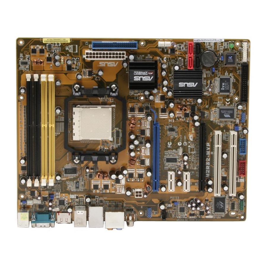
2.2.3 2.2.3 2.2.3 Motherboard layout Motherboard layout Motherboard layout 2.2.3 2.2.3 Motherboard layout Motherboard layout KBPWR1 PS/2KBMS T: Mouse B: Keyboard DDR2 DIMM_B2 (64 bit,240-pin module) CHA_FAN2 DDR2 DIMM_A2 (64 bit,240-pin module) CPU_FAN DDR2 DIMM_B1 (64 bit,240-pin module) DDR2 DIMM_A1 (64 bit,240-pin module) JMB360 F_USB12 LAN_USB34... -
Page 28: Layout Contents
2.2.4 2.2.4 2.2.4 Layout Contents Layout Contents Layout Contents 2.2.4 2.2.4 Layout Contents Layout Contents S l o t s S l o t s S l o t s S l o t s S l o t s DDR DIMM slots PCI slots PCI Express x1 slots... - Page 29 I n t e r n a l c o n n e c t o r s I n t e r n a l c o n n e c t o r s I n t e r n a l c o n n e c t o r s I n t e r n a l c o n n e c t o r s I n t e r n a l c o n n e c t o r s Floppy disk drive connector (34-1 pin FLOPPY)
-
Page 30: Central Processing Unit (Cpu)
Central Processing Unit (CPU) The motherboard comes with a 940-pin AM2 socket designed for the AMD Athlon™ 64 X2/Athlon™ 64/Athlon™ FX/Sempron™ processor. The AM2 socket has a different pinout from the 939-pin socket designed for the AMD Opteron™ processor. Make sure you use a CPU is designed for the AM2 socket. - Page 31 Position the CPU above the socket such that the CPU corner with the gold triangle matches the socket corner with a small triangle. Carefully insert the CPU into the socket until it fits in place. The CPU fits only in one correct orientation. DO NOT force the CPU into the socket to prevent bending the pins and damaging the CPU! When the CPU is in place, push down the socket lever to secure...
-
Page 32: Installing The Heatsink And Fan
2.3.2 2.3.2 2.3.2 Installing the heatsink and fan Installing the heatsink and fan Installing the heatsink and fan 2.3.2 2.3.2 Installing the heatsink and fan Installing the heatsink and fan The AMD Athlon™ 64 X2/Athlon™ 64 FX/Athlon™ 64/Sempron™ processor requires a specially designed heatsink and fan assembly to ensure optimum thermal condition and performance. - Page 33 Attach one end of the retention bracket to the retention module base. Align the other end of the retention bracket (near the retention bracket lock) to the retention module base. A clicking sound denotes that the retention bracket is in place. Make sure that the fan and heatsink assembly perfectly fits the retention mechanism module...
- Page 34 When the fan and heatsink assembly is in place, connect the CPU fan cable to the connector on the motherboard labeled CPU_FAN. M2R32-MVP M2R32-MVP CPU fan connector Do not forget to connect the CPU fan connector! Hardware monitoring errors can occur if you fail to plug this connector. 2 - 1 0 2 - 1 0 2 - 1 0...
-
Page 35: System Memory
System memory 2.4.1 2.4.1 2.4.1 2.4.1 2.4.1 Overview Overview Overview Overview Overview The motherboard comes with four Double Data Rate 2 (DDR2) Dual Inline Memory Modules (DIMM) sockets. A DDR2 module has the same physical dimensions as a DDR DIMM but has a 240-pin footprint compared to the 184-pin DDR DIMM. -
Page 36: Memory Configurations
2.4.2 2.4.2 2.4.2 Memory configurations Memory configurations Memory configurations 2.4.2 2.4.2 Memory configurations Memory configurations You may install 256 MB, 512 MB, 1 GB, and 2 GB unbuffered ECC/non-ECC DDR2 DIMMs into the DIMM sockets. • For dual-channel configuration, the total size of memory module(s) installed per channel must be the same (DIMM_A1+ DIMM_B1 = DIMM_A2+ DIMM_B2) •... - Page 37 Dual-channel memory configuration S S - Single-sided D S - Double-sided Visit the ASUS website (www.asus.com) for the latest Qualified Vendors List. A S U S M 2 R 3 2 - M V P A S U S M 2 R 3 2 - M V P...
- Page 38 C C C C C - Supports 4 modules inserted into the yellow and black slots as two pairs of Dual-channel memory configuration S S - Single-sided D S - Double-sided Visit the ASUS website (www.asus.com) for the latest Qualified Vendors List. 2 - 1 4 2 - 1 4...
- Page 39 Dual-channel memory configuration S S - Single-sided D S - Double-sided Visit the ASUS website (www.asus.com) for the latest Qualified Vendors List. A S U S M 2 R 3 2 - M V P A S U S M 2 R 3 2 - M V P...
-
Page 40: Installing A Ddr2 Dimm
2.4.3 2.4.3 2.4.3 Installing a DIMM Installing a DIMM Installing a DIMM 2.4.3 2.4.3 Installing a DIMM Installing a DIMM Make sure to unplug the power supply before adding or removing DIMMs or other system components. Failure to do so may cause severe damage to both the motherboard and the components. -
Page 41: Expansion Slots
Expansion slots In the future, you may need to install expansion cards. The following sub-sections describe the slots and the expansion cards that they support. Make sure to unplug the power cord before adding or removing expansion cards. Failure to do so may cause you physical injury and damage motherboard components. -
Page 42: Interrupt Assignments
2.5.3 2.5.3 2.5.3 Interrupt assignments Interrupt assignments Interrupt assignments 2.5.3 2.5.3 Interrupt assignments Interrupt assignments Standard interrupt assignments Standard interrupt assignments Standard interrupt assignments Standard interrupt assignments Standard interrupt assignments I R Q I R Q I R Q I R Q I R Q P r i o r i t y P r i o r i t y... -
Page 43: Two Pci Slots
2.5.4 2.5.4 2.5.4 2.5.4 2.5.4 Two PCI slots Two PCI slots Two PCI slots Two PCI slots Two PCI slots The PCI slots support cards such as a LAN card, SCSI card, USB card, and other cards that comply with PCI specifications. - Page 44 • We recommend that you install a VGA card on the primary (blue) PCI Express slot and install any other PCI Express device on the secondary (black) PCI Express slot. • I n C r o s s F i r e ™ m o d e , i n s t a l l t h e A T I C r o s s F i r e ™ E d i t i o n I n C r o s s F i r e ™...
-
Page 45: Jumper
Jumper 1 . 1 . C l e a r R T C R A M ( C L R T C ) C l e a r R T C R A M ( C L R T C ) C l e a r R T C R A M ( C L R T C ) C l e a r R T C R A M ( C L R T C ) C l e a r R T C R A M ( C L R T C ) - Page 46 2 . 2 . U S B d e v i c e w a k e - u p ( 3 - p i n U S B P W 1 2 , U S B P W 3 4 , U S B d e v i c e w a k e - u p ( 3 - p i n U S B P W 1 2 , U S B P W 3 4 , U S B d e v i c e w a k e - u p ( 3 - p i n U S B P W 1 2 , U S B P W 3 4 , U S B d e v i c e w a k e - u p ( 3 - p i n U S B P W 1 2 , U S B P W 3 4 ,...
- Page 47 3 . 3 . K e y b o a r d p o w e r ( 3 - p i n K B P W R 1 ) K e y b o a r d p o w e r ( 3 - p i n K B P W R 1 ) K e y b o a r d p o w e r ( 3 - p i n K B P W R 1 ) K e y b o a r d p o w e r ( 3 - p i n K B P W R 1 ) K e y b o a r d p o w e r ( 3 - p i n K B P W R 1 )
-
Page 48: Connectors
Connectors 2.7.1 2.7.1 2.7.1 2.7.1 2.7.1 Rear panel connectors Rear panel connectors Rear panel connectors Rear panel connectors Rear panel connectors 1 . 1 . P S / 2 m o u s e p o r t ( g r e e n ) . This port is for a PS/2 mouse. P S / 2 m o u s e p o r t ( g r e e n ) . - Page 49 Audio 2, 4, 6, or 8-channel configuration Audio 2, 4, 6, or 8-channel configuration Audio 2, 4, 6, or 8-channel configuration Audio 2, 4, 6, or 8-channel configuration Audio 2, 4, 6, or 8-channel configuration P o r t P o r t P o r t P o r t P o r t...
-
Page 50: Internal Connectors
2.7.2 2.7.2 2.7.2 Internal connectors Internal connectors Internal connectors 2.7.2 2.7.2 Internal connectors Internal connectors 1 . 1 . F l o p p y d i s k d r i v e c o n n e c t o r ( 3 4 - 1 p i n F L O P P Y ) F l o p p y d i s k d r i v e c o n n e c t o r ( 3 4 - 1 p i n F L O P P Y ) F l o p p y d i s k d r i v e c o n n e c t o r ( 3 4 - 1 p i n F L O P P Y ) F l o p p y d i s k d r i v e c o n n e c t o r ( 3 4 - 1 p i n F L O P P Y ) -
Page 51: Hard Disk Drives
D r i v e j u m p e r D r i v e j u m p e r D r i v e j u m p e r D r i v e j u m p e r D r i v e j u m p e r s e t t i n g s e t t i n g... - Page 52 Connect the right-angle side of SATA signal cable to SATA device. Or you may connect the right-angle side of SATA cable to the onboard SATA port to avoid mechanical conflict with huge graphics cards. • Plug your Serial ATA boot disk on the master port (SATA1/3 to support S3 function).
- Page 53 M2R32-MVP Fan connectors Only the CPU_FAN, CHA_FAN1, and CHA_FAN2 connectors support the ASUS Q-Fan 2 feature. A S U S M 2 R 3 2 - M V P A S U S M 2 R 3 2 - M V P...
- Page 54 5 . 5 . U S B c o n n e c t o r s ( 1 0 - 1 p i n U S B 5 6 , U S B 7 8 , U S B 9 1 0 ) U S B c o n n e c t o r s ( 1 0 - 1 p i n U S B 5 6 , U S B 7 8 , U S B 9 1 0 ) U S B c o n n e c t o r s ( 1 0 - 1 p i n U S B 5 6 , U S B 7 8 , U S B 9 1 0 ) U S B c o n n e c t o r s ( 1 0 - 1 p i n U S B 5 6 , U S B 7 8 , U S B 9 1 0 )
- Page 55 • For a fully-configured system, we recommend that you use a power supply unit (PSU) that complies with ATX 12 V Specification 2.0 (or later version) and provides a minimum power of 400 W. • Do not forget to connect the 4-pin ATX +12 V power plug; otherwise, the system will not boot up.
- Page 56 8 . 8 . C h a s s i s i n t r u s i o n c o n n e c t o r ( 4 - 1 p i n C H A S S I S ) C h a s s i s i n t r u s i o n c o n n e c t o r ( 4 - 1 p i n C H A S S I S ) C h a s s i s i n t r u s i o n c o n n e c t o r ( 4 - 1 p i n C H A S S I S ) C h a s s i s i n t r u s i o n c o n n e c t o r ( 4 - 1 p i n C H A S S I S )
- Page 57 1 0 . 1 0 . F r o n t p a n e l a u d i o c o n n e c t o r ( 1 0 - 1 p i n A A F P ) 1 0 .
- Page 58 1 2 . S y s t e m p a n e l c o n n e c t o r ( 2 0 - 8 p i n P A N E L ) 1 2 . 1 2 .
- Page 59 Q - C o n n e c t o r ( S y s t e m p a n e l ) ASUS Q-Connector allows you to easily connect the chassis front panel cables to the motherboard. Perform these steps to install ASUS Q- Connector.
- Page 60 2 - 3 6 2 - 3 6 2 - 3 6 2 - 3 6 2 - 3 6 C h a p t e r 2 : H a r d w a r e i n f o r m a t i o n C h a p t e r 2 : H a r d w a r e i n f o r m a t i o n C h a p t e r 2 : H a r d w a r e i n f o r m a t i o n C h a p t e r 2 : H a r d w a r e i n f o r m a t i o n...
- Page 61 This chapter describes the power up sequence, the vocal POST messages, and ways of shutting down the system. Powering up...
- Page 62 Chapter summary Starting up for the first time ... 3-1 Powering off the computer ... 3-2 A S U S M 2 R 3 2 - M V P A S U S M 2 R 3 2 - M V P A S U S M 2 R 3 2 - M V P A S U S M 2 R 3 2 - M V P A S U S M 2 R 3 2 - M V P...
-
Page 63: Starting Up For The First Time
Starting up for the first time After making all the connections, replace the system case cover. Be sure that all switches are off. Connect the power cord to the power connector at the back of the system chassis. Connect the power cord to a power outlet that is equipped with a surge protector. -
Page 64: Powering Off The Computer
Powering off the computer 3.2.1 3.2.1 3.2.1 3.2.1 3.2.1 Using the OS shut down function Using the OS shut down function Using the OS shut down function Using the OS shut down function Using the OS shut down function If you are using Windows S t a r t S t a r t Click the S t a r t... -
Page 65: Chapter 4: Bios Setup
This chapter tells how to change the system settings through the BIOS Setup menus. Detailed descriptions of the BIOS parameters are also provided. BIOS setup... - Page 66 Chapter summary Managing and updating your BIOS ... 4-1 BIOS setup program ... 4-11 Main menu ... 4-14 Advanced menu ... 4-18 Power menu ... 4-32 Boot menu ... 4-37 Tools menu ... 4-42 Exit menu ... 4-45 A S U S M 2 R 3 2 - M V P A S U S M 2 R 3 2 - M V P A S U S M 2 R 3 2 - M V P A S U S M 2 R 3 2 - M V P...
-
Page 67: Managing And Updating Your Bios
4.1.1 ASUS Update utility ASUS Update utility ASUS Update utility The ASUS Update is a utility that allows you to manage, save, and update the motherboard BIOS in Windows allows you to: • Save the current BIOS file • Download the latest BIOS file from the Internet •... - Page 68 A S U S U p d a t e A S U S U p d a t e A S U S U p d a t e. The ASUS Update main window appears. A S U S U p d a t e...
- Page 69 P r o g r a m s > A S U S P r o g r a m s A S U S U p d a t e. The ASUS Update main window appears. A S U S U p d a t e...
-
Page 70: Creating A Bootable Floppy Disk
4.1.2 4.1.2 4.1.2 Creating a bootable floppy disk Creating a bootable floppy disk Creating a bootable floppy disk 4.1.2 4.1.2 Creating a bootable floppy disk Creating a bootable floppy disk Do either one of the following to create a bootable floppy disk. DOS environment a. -
Page 71: Asus Ez Flash Utility
ASUS EZ Flash 2 utility ASUS EZ Flash 2 utility The ASUS EZ Flash 2 feature allows you to update the BIOS without having to go through the long process of booting from a floppy disk and using a DOS-based utility. The EZ Flash 2 utility is built in the BIOS chip so it is accessible by pressing <Alt>... -
Page 72: Afudos Utility
4.1.4 4.1.4 4.1.4 AFUDOS utility AFUDOS utility AFUDOS utility 4.1.4 4.1.4 AFUDOS utility AFUDOS utility The AFUDOS utility allows you to update the BIOS file in DOS environment using a bootable floppy disk with the updated BIOS file. This utility also allows you to copy the current BIOS file that you can use as backup when the BIOS fails or gets corrupted during the updating process. - Page 73 Updating the BIOS file To update the BIOS file using the AFUDOS utility: Visit the ASUS website (www.asus.com) and download the latest BIOS file for the motherboard. Save the BIOS file to a bootable floppy disk. Write the BIOS filename on a piece of paper. You need to type the exact BIOS filename at the DOS prompt.
- Page 74 The utility returns to the DOS prompt after the BIOS update process is completed. Reboot the system from the hard disk drive. A:\>afudos /iM2R32-MVP.ROM AMI Firmware Update Utility - Version 1.19(ASUS V2.07(03.11.24BB)) Copyright (C) 2003 American Megatrends, Inc. All rights reserved. WARNING!! Do not turn off power during flash BIOS Reading file ...
-
Page 75: Asus Crashfree Bios 2 Utility
ASUS CrashFree BIOS 3 utility ASUS CrashFree BIOS 3 utility The ASUS CrashFree BIOS 3 is an auto recovery tool that allows you to restore the BIOS file when it fails or gets corrupted during the updating process. You can update a corrupted BIOS file using the motherboard support CD, the floppy disk, or the USB flash disk that contains the updated BIOS file. - Page 76 Restart the system after the utility completes the updating process. • Only the USB flash disk with FAT 32/16 format and single partition can support ASUS CrashFree BIOS 3. The device size should be smaller than 8 GB. • Flash time takes around one minute.
-
Page 77: Bios Setup Program
• Visit the ASUS website (www.asus.com) to download the latest BIOS file for this motherboard. A S U S M 2 R 3 2 - M V P... -
Page 78: Bios Menu Screen
Tools [10:55:25] [Fri 07/21/2006] [1.44M, 3.5 in] [English] [ST320410A] [ASUS CD-S520/A] [Not Detected] [Not Detected] [Not Detected] [Not Detected] G e n e r a l h e l p G e n e r a l h e l p... -
Page 79: Menu Items
[10:55:25] System Date [Wed 10/ 25/2005] Legacy Diskette A [1.44M, 3.5 in.] Language [English] Primary IDE Master [ST320410A] Primary IDE Slave [ASUS CD-S520/A] SATA1 [Not Detected] SATA2 [Not Detected] SATA3 [Not Detected] SATA4 [Not Detected] Storage Configuration System Information v02.58 (C)Copyright 1985-2006,American Megatrends, Inc. -
Page 80: Main Menu
BIOS SETUP UTILITY Power Boot Tools Exit [10:55:25] [Mon 10/25/2005] [1.44M, 3.5 in] [English] [ST320410A] [ASUS CD-S520/A] [Not Detected] [Not Detected] [Not Detected] [Not Detected] Use [ENTER], [TAB] or [SHIFT-TAB] to select a field. Use [+] or [-] to configure the System Time. -
Page 81: Primary Ide Master/Slave Sata1-4
4.3.5 4.3.5 4.3.5 Primary IDE Master/Slave Primary IDE Master/Slave Primary IDE Master/Slave 4.3.5 4.3.5 Primary IDE Master/Slave Primary IDE Master/Slave SATA1-4 SATA1-4 SATA1-4 SATA1-4 SATA1-4 The BIOS automatically detects the connected IDE/Serial ATA devices. There is a separate sub-menu for each IDE/SATA device. Select a device item, then press <Enter>... -
Page 82: Storage Configuration
PIO Mode [Auto] PIO Mode [Auto] PIO Mode [Auto] PIO Mode [Auto] PIO Mode [Auto] Selects the PIO mode. Configuration options: [Auto] [0] [1] [2] [3] [4] DMA Mode [Auto] DMA Mode [Auto] DMA Mode [Auto] DMA Mode [Auto] DMA Mode [Auto] Selects the DMA mode. -
Page 83: System Information
The succeeding item appears only if the O n C h i p S A T A C h a n n e l is set to [Enabled]. OnChip SATA Type [Native IDE] Allows you to select the onchip SATA type. Configuration options: [Native IDE] [RAID] [AHCI] [Legacy IDE] 4.3.7 4.3.7... -
Page 84: Advanced Menu
Advanced menu The Advanced menu items allow you to change the settings for the CPU and other system devices. Take caution when changing the settings of the Advanced menu items. Incorrect field values can cause the system to malfunction. Main Advanced Jumperfree Configuration CPU Configuration... - Page 85 A I N . O . S . A I N . O . S . A I N . O . S . the ASUS AI Non-delay Overclocking System feature intelligently determines the system load and automatically boost the performance for the most demanding tasks.
- Page 86 CPU:ATI-NB HT Link Speed [Auto] CPU:ATI-NB HT Link Speed [Auto] CPU:ATI-NB HT Link Speed [Auto] CPU:ATI-NB HT Link Speed [Auto] CPU:ATI-NB HT Link Speed [Auto] Configuration options: [Auto] [x1 200 MHz] [x2 400 MHz] [x3 600 MHz] [x4 800 MHz] [x5 1 GHz] DDR Voltage [Auto] DDR Voltage [Auto] DDR Voltage [Auto]...
- Page 87 The following item appears only when you set the A I O v e r c l o c k i n g item to [Ovrerclock Profile]. Overclock Options [Overclock 5%] Overclock Options [Overclock 5%] Overclock Options [Overclock 5%] Overclock Options [Overclock 5%] Overclock Options [Overclock 5%] Allows you to overclock the CPU speed through the available preset values.
-
Page 88: Cpu Configuration
4.4.2 4.4.2 4.4.2 CPU Configuration CPU Configuration CPU Configuration 4.4.2 4.4.2 CPU Configuration CPU Configuration The items in this menu show the CPU-related information that the BIOS automatically detects. Advanced CPU Configuration Module Version: 13.05 AGESA Version: 02.06.09 Physical Count: 1 Logical Count: 2 AMD Athlon(tm) 64 X2 Dual Core Processor 4800+ Revision: F2... - Page 89 Memory Controller Memory Controller Memory Controller Memory Controller Memory Controller Advanced Memory Controller Memory Configuration Power Down Control Alternate VID Current Memory CLK Current CAS Latency (CL) Current RAS/CAS Delay (Trcd) : 3 CLK Current TRAS Current TRP Current TRRD Current TRC Asynchronous Latency v02.58 (C)Copyright 1985-2006, American Megatrends, Inc.
- Page 90 CAS Latency (CL) [Auto] Configuration options: [Auto] [3.0] [4.0] [5.0] [6.0] TRCD [Auto] Configuration options: [Auto] [3 CLK] [4 CLK] [5 CLK] [6 CLK] TRP [Auto] Configuration options: [Auto] [3 CLK] [4 CLK] [5 CLK] [6 CLK] TRAS [Auto] Configuration options: [Auto] [5 CLK] [6 CLK] [7 CLK]...[18 CLK] 2T Mode [Auto] Configuration options: [Auto] [Disabled] [Enable] MCT Timing Mode [Auto]...
-
Page 91: Chipset
Alternate VID [Auto] Alternate VID [Auto] Alternate VID [Auto] Alternate VID [Auto] Alternate VID [Auto] Specifies the alternate VID while in low power state. Configuration options: [1.550 V] [1.525 V] [1.500 V] [1.475 V] [1.450]...[0.825 V] [0.800 V] [Auto] 4.4.3 4.4.3 4.4.3 4.4.3... - Page 92 RD580 HT Link Three State [Disabled] Configuration options: [Disabled] [Enabled] RD580 RD580 HT Drive Strength [Auto] Configuration options: [Auto] [Optimal] RD580 HT Receiver Comp. Ctrl [Auto] Configuration options: [Auto] [Optimal] RD580 HT PLL Control [Auto] Configuration options: [Auto] [Low Speed] [High Speed] PCI Express Configuration PCI Express Configuration PCI Express Configuration...
-
Page 93: Onboard Devices Configuration
4.4.4 4.4.4 Onboard Devices Configuration Onboard Devices Configuration 4.4.4 4.4.4 4.4.4 Onboard Devices Configuration Onboard Devices Configuration Onboard Devices Configuration Advanced Onboard Devices HD Audio Azalia Device Front Panel Support Type Onboard LAN Onboard LAN Boot ROM External SATA Controller Mode IEEE 1394 controller Serial Port1 Address v02.58 (C)Copyright 1985-2006, American Megatrends, Inc. - Page 94 Controller Mode [IDE] This item allows you to set the external SATA controller mode. This item appears only when the E x t e r n a l S A T A Configuration options: [IDE] [AHCI] IEEE1394 [Enabled] IEEE1394 [Enabled] IEEE1394 [Enabled] IEEE1394 [Enabled] IEEE1394 [Enabled]...
-
Page 95: Pci Pnp
4.4.5 4.4.5 4.4.5 PCI PnP PCI PnP PCI PnP 4.4.5 4.4.5 PCI PnP PCI PnP The PCI PnP menu items allow you to change the advanced settings for PCI/PnP devices. The menu includes setting IRQ and DMA channel resources for either PCI/PnP or legacy ISA devices, and setting the memory size block for legacy ISA devices. -
Page 96: Usb Configuration
IRQ-xx assigned to [PCI Device] IRQ-xx assigned to [PCI Device] IRQ-xx assigned to [PCI Device] IRQ-xx assigned to [PCI Device] IRQ-xx assigned to [PCI Device] When set to [PCI Device], the specific IRQ is free for use of PCI/PnP devices. When set to [Reserved], the IRQ is reserved for legacy ISA devices. - Page 97 USB 2.0 Controller Mode [HiSpeed] USB 2.0 Controller Mode [HiSpeed] USB 2.0 Controller Mode [HiSpeed] USB 2.0 Controller Mode [HiSpeed] USB 2.0 Controller Mode [HiSpeed] Allows you to set the USB 2.0 controller mode to HiSpeed (480 Mbps) or FullSpeed (12 Mbps). Configuration options: [FullSpeed] [HiSpeed] BIOS EHCI Hand-off [Enabled] BIOS EHCI Hand-off [Enabled] BIOS EHCI Hand-off [Enabled]...
-
Page 98: Power Menu
Power menu The Power menu items allow you to change the settings for the ACPI and Advanced Power Management (APM) features. Select an item then press <Enter> to display the configuration options. Main Advanced Suspend Mode Repost Video on S3 Resume ACPI Version Features ACPI APIC Support APM Configuration... -
Page 99: Apm Configuration
4.5.5 4.5.5 4.5.5 APM Configuration APM Configuration APM Configuration 4.5.5 4.5.5 APM Configuration APM Configuration Power Power Button Mode Restore on AC Power Loss Power On By PS/2 Keyboard Power On By PS/2 Mouse Power On By External Modems Power On By PCI/PCIe Devices RTC Resume v02.58 (C)Copyright 1985-2005, American Megatrends, Inc. - Page 100 The computer cannot receive or transmit data until the computer and applications are fully running. Thus, connection cannot be made on the first try. Turning an external modem off and then back on while the computer is off causes an initialization string that turns the system power on.
-
Page 101: Hardware Monitor
4.5.6 4.5.6 4.5.6 Hardware Monitor Hardware Monitor Hardware Monitor 4.5.6 4.5.6 Hardware Monitor Hardware Monitor Power Hardware Monitor CPU Temperature MB Temperature CPU Fan Speed Chassis Fan Speed Chassis Fan2 Speed Power Fan Speed VCORE Voltage 3.3V Voltage 5V Voltage 12V Voltage Smart Q-Fan Function v02.53 (C)Copyright 1985-2004, American Megatrends, Inc. - Page 102 [Disabled] [Disabled] [Disabled] Allows you to enable or disable the ASUS Q-Fan feature that smartly adjusts the fan speeds for more efficient system operation. Configuration options: [Disabled] [Enabled] The following items appear when the S m a r t Q - F A N F u n c t i o n set to [Enabled].
-
Page 103: Boot Menu
Enter Go to Sub Screen BIOS SETUP UTILITY Boot Specifies the boot sequence from the [1st FLOPPY DRIVE] availabe devices. [PM-ST320410A] [PS-ASUS CD-S520/A] A device enclosed in parenthesis has been disabled in the corresponding menu. Select Screen Select Item General Help... -
Page 104: Boot Settings Configuration
Hard Disk [XXX Drive] Hard Disk [XXX Drive] Hard Disk [XXX Drive] Hard Disk [XXX Drive] Hard Disk [XXX Drive] This item specifies the Serial ATA boot device priority sequence from the available devices in a RAID configuration. Configuration options: [xxxxx Drive] [Disabled] 4.6.2 4.6.2 4.6.2... -
Page 105: Security
PS/2 Mouse Support [Auto] PS/2 Mouse Support [Auto] PS/2 Mouse Support [Auto] PS/2 Mouse Support [Auto] PS/2 Mouse Support [Auto] Allows you to enable or disable support for PS/2 mouse. Configuration options: [Disabled] [Enabled] [Auto] Wait For ‘F1’ If Error [Enabled] Wait For ‘F1’... - Page 106 To set a Supervisor Password: Select the Change Supervisor Password item and press <Enter>. From the password box, type a password composed of at least six letters and/or numbers, then press <Enter>. Confirm the password when prompted. The message “Password Installed” appears after you successfully set your password.
- Page 107 L i m i t e d L i m i t e d L i m i t e d allows changes only to selected fields, such as Date and L i m i t e d L i m i t e d Time.
-
Page 108: Tools Menu
ASUS EZ Flash 2 ASUS EZ Flash 2 Allows you to run ASUS EZ Flash 2. When you press <Enter>, a confirmation message appears. Use the left/right arrow key to select between [Yes] or [No], then press <Enter> to confirm your choice. Please see page 4-5, section 4.1.3 for details. -
Page 109: Asus O.c. Profile
4.7.2 4.7.2 4.7.2 ASUS O.C. Profile ASUS O.C. Profile ASUS O.C. Profile 4.7.2 4.7.2 ASUS O.C. Profile ASUS O.C. Profile Main Advanced Power O.C. PROFILE Configuration O.C. Profile 1 Status: Not Installed O.C. Profile 2 Status: Not Installed Save to Profile 1... - Page 110 • This function can supp0ort devices such as USB flash disk, or floppy disk with FAT 32/16 format and single partition only. • Do not shutdown or reset the system while updating the BIOS to prevent system boot failure! 4 - 4 4 4 - 4 4 4 - 4 4 4 - 4 4...
-
Page 111: Exit Menu
Exit menu The Exit menu items allow you to load the optimal or failsafe default values for the BIOS items, and save or discard your changes to the BIOS items. Main Advanced Power Exit Options Exit & Save Changes Exit & Discard Changes Discard Changes Load Setup Defaults v02.58 (C)Copyright 1985-2005, American Megatrends, Inc. - Page 112 Load Setup Defaults Load Setup Defaults Load Setup Defaults Load Setup Defaults Load Setup Defaults This option allows you to load the default values for each of the parameters on the Setup menus. When you select this option or if you press <F5>, a confirmation window appears.
- Page 113 This chapter describes the contents of the support CD that comes with the motherboard package. Software support...
- Page 114 Chapter summary Installing an operating system ... 5-1 Support CD information ... 5-1 Software information ... 5-9 RAID configurations ... 5-25 Creating a RAID driver disk ... 5-32 A S U S M 2 R 3 2 - M V P A S U S M 2 R 3 2 - M V P A S U S M 2 R 3 2 - M V P A S U S M 2 R 3 2 - M V P...
-
Page 115: Installing An Operating System
The contents of the support CD are subject to change at any time without notice. Visit the ASUS website(www.asus.com) for updates. 5.2.1 5.2.1 Running the support CD Running the support CD 5.2.1... -
Page 116: Drivers Menu
5.2.2 5.2.2 5.2.2 Drivers menu Drivers menu Drivers menu 5.2.2 5.2.2 Drivers menu Drivers menu The drivers menu shows the available device drivers if the system detects installed devices. Install the necessary drivers to activate the devices. ATI Chipset Driver ATI Chipset Driver ATI Chipset Driver ATI Chipset Driver... -
Page 117: Utilities Menu
ASUS Update ASUS Update ASUS Update ASUS Update The ASUS Update utility that allows you to update the motherboard BIOS in Windows ® environment. This utility requires an Internet connection either through a network or an Internet Service Provider (ISP). See section “4.1.1 ASUS Update utility”... - Page 118 Adobe Reader V7.0 Adobe Reader V7.0 Adobe Reader V7.0 Adobe Reader V7.0 Adobe Reader V7.0 Installs the Adobe ® print documents in Portable Document Format (PDF). Microsoft DirectX 9.0c Microsoft DirectX 9.0c Microsoft DirectX 9.0c Microsoft DirectX 9.0c Microsoft DirectX 9.0c Installs the Microsoft is a multimedia technology that enhances computer graphics and sound.
-
Page 119: Make Disk Menu
5.2.4 5.2.4 5.2.4 Make Disk menu Make Disk menu Make Disk menu 5.2.4 5.2.4 Make Disk menu Make Disk menu The Make Disk menu contains the item needed to create the ULI Serial ATA/RAID driver disk. Make ATI RAID Driver Make ATI RAID Driver Make ATI RAID Driver Make ATI RAID Driver... -
Page 120: Manuals Menu
5.2.5 5.2.5 5.2.5 Manuals menu Manuals menu Manuals menu 5.2.5 5.2.5 Manuals menu Manuals menu The Manuals menu contains a list of supplementary user manuals. Click an item to open the folder of the user manual. Most user manual files are in Portable Document Format (PDF). Install the Adobe ®... -
Page 121: Asus Contact Information
C o n t a c t C o n t a c t C o n t a c t tab to display the ASUS contact information. You can also find this information on the inside front cover of this user guide. - Page 122 Displays the contents of the support CD in graphical format. Technical Support Form Technical Support Form Technical Support Form Technical Support Form Technical Support Form Displays the ASUS Technical Support Request Form that you have to fill out when requesting technical support. Filelist Filelist Filelist Filelist Filelist Displays the contents of the support CD in text format.
-
Page 123: Software Information
5.3.1 ASUS MyLogo2™ ASUS MyLogo2™ The ASUS MyLogo2™ utility lets you customize the boot logo. The boot logo is the image that appears on screen during the Power-On-Self-Tests (POST). The ASUS MyLogo™ is automatically installed when you install the A S U S U p d a t e A S U S U p d a t e A S U S U p d a t e utility from the support CD. - Page 124 R a t i o R a t i o When the screen returns to the ASUS Update utility, flash the original BIOS to load the new boot logo. 10. After flashing the BIOS, restart the computer to display the new boot logo during POST.
-
Page 125: Ai Net 2
5.3.2 5.3.2 5.3.2 AI Net 2 AI Net 2 AI Net 2 5.3.2 5.3.2 AI Net 2 AI Net 2 The Marvell ® Virtual Cable Tester™ (VCT) is a cable diagnostic utility that reports LAN cable faults and shorts using the Time Domain Reflectometry (TDR) technology. -
Page 126: Asus Pc Probe Ii
Autorun feature. If Autorun is not enabled in your computer, browse the contents of the support CD to locate the setup.exe file from the ASUS PC Probe II folder. Double-click the setup.exe file to start installation. - Page 127 B u t t o n B u t t o n B u t t o n B u t t o n B u t t o n F u n c t i o n F u n c t i o n F u n c t i o n F u n c t i o n F u n c t i o n...
- Page 128 Hardware monitor panels Hardware monitor panels Hardware monitor panels Hardware monitor panels Hardware monitor panels The hardware monitor panels display the current value of a system sensor such as fan rotation, CPU temperature, and voltages. The hardware monitor panels come in two display modes: hexagonal (large) and rectangular (small).
-
Page 129: Desktop Management Interface
Monitoring sensor alert The monitor panel turns red when a component value exceeds or is lower than the threshold value. Refer to the illustrations below. L a r g e d i s p l a y L a r g e d i s p l a y L a r g e d i s p l a y L a r g e d i s p l a y L a r g e d i s p l a y... - Page 130 PCI browser PCI browser PCI browser PCI browser PCI browser Click to display the PCI (Peripheral Component Interconnect) browser. This browser provides information on the PCI devices installed on your system. Click the plus sign (+) before the P C I I n f o r m a t i o n P C I I n f o r m a t i o n P C I I n f o r m a t i o n P C I I n f o r m a t i o n...
- Page 131 Memory usage The Memory tab shows both used and available physical memory. The pie chart at the bottom of the window represents the used (blue) and the available physical memory. Configuring PC Probe II Configuring PC Probe II Configuring PC Probe II Configuring PC Probe II Configuring PC Probe II Click...
-
Page 132: Cool 'N' Quiet™ Technology
5.3.4 5.3.4 5.3.4 Cool ‘n’ Quiet™ Technology Cool ‘n’ Quiet™ Technology Cool ‘n’ Quiet™ Technology 5.3.4 5.3.4 Cool ‘n’ Quiet™ Technology Cool ‘n’ Quiet™ Technology The motherboard supports the AMD Cool ‘n’ Quiet™ Technology that dynamically and automatically change the CPU speed, voltage, and amount of power depending on the task the CPU performs. - Page 133 Launching the Cool ‘n’ Quiet™ software Launching the Cool ‘n’ Quiet™ software Launching the Cool ‘n’ Quiet™ software Launching the Cool ‘n’ Quiet™ software Launching the Cool ‘n’ Quiet™ software The motherboard support CD includes the Cool ‘n’ Quie!™ software that enables you to view your system’s real-time CPU Frequency and voltage.
-
Page 134: Soundmax High Definition Audio Utility
5.3.5 5.3.5 5.3.5 SoundMAX SoundMAX SoundMAX 5.3.5 5.3.5 SoundMAX SoundMAX The ADI AD1988A High Definition Audio CODEC provides 8-channel audio capability through the SoundMAX deliver the ultimate audio experience on your PC. The software implements high quality audio synthesis/rendering, 3D sound positioning, and advanced voice-input technologies. - Page 135 From the taskbar, double-click on the SoundMAX SoundMAX ® Control Panel. Audio Setup Wizard Audio Setup Wizard Audio Setup Wizard Audio Setup Wizard Audio Setup Wizard By clicking the icon from the SoundMAX configure your audio settings. Simply follow succeeding screen instructions and begin enjoying High Definition Audio.
- Page 136 Jack configuration Jack configuration Jack configuration Jack configuration Jack configuration This screen helps you configure your computer’s audio ports, depending on the audio devices you have installed. Adjust microphone volume Adjust microphone volume Adjust microphone volume Adjust microphone volume Adjust microphone volume This screen helps you adjust microphone volume.
- Page 137 Audio preferences Audio preferences Audio preferences Audio preferences Audio preferences Click the icon to go to the Preferences page. This page allows you to change various audio settings. General options General options General options General options General options Click the General tab to choose your playback and recording devices, enable/ disable the AudioESP™...
- Page 138 Microphone options Microphone options Microphone options Microphone options Microphone options Click the Microphone tab to optimize your microphone input settings. Enhanced Microphone Features Enhanced Microphone Features Enhanced Microphone Features Enhanced Microphone Features Enhanced Microphone Features No Filtering Enables Noise Filter function. Detects repetitive and stationary noises like computer fans, air conditioners, and other background noises then eliminates it in the incoming sudio stream while recording.
-
Page 139: Raid Configurations
RAID Configurations The motherboard comes with a RAID controller integrated in the SB600 Southbridge that allows you to configure Serial ATA hard disk drives as RAID sets. The motherboard supports the following RAID configurations. R A I D 0 R A I D 0 (Data striping) optimizes two identical hard disk drives to read and R A I D 0 R A I D 0 R A I D 0... -
Page 140: Installing Hard Disks
5.4.1 5.4.1 5.4.1 Installing hard disks Installing hard disks Installing hard disks 5.4.1 5.4.1 Installing hard disks Installing hard disks The motherboard supports Ultra DMA 133/100/66 and Serial ATA hard disk drives. For optimal performance, install identical drives of the same model and capacity when creating a disk array. - Page 141 A T I A T I A T I A T I A T I ® ® ® ® ® FastBuild™ Utility FastBuild™ Utility FastBuild™ Utility FastBuild™ Utility FastBuild™ Utility To enter the ATI ® FastBuild™ utility: Boot up your computer. Press <Ctrl+F>...
- Page 142 Creating a RAID 0 configuration Creating a RAID 0 configuration Creating a RAID 0 configuration Creating a RAID 0 configuration Creating a RAID 0 configuration To create a RAID 0 set: In the Main Menu, press <2> to enter the “Define LD” function. Press <Enter>, and the following screen appears.
- Page 143 Creating a RAID 1 configuration Creating a RAID 1 configuration Creating a RAID 1 configuration Creating a RAID 1 configuration Creating a RAID 1 configuration To create a RAID 1 set: In the Main Menu, press <2> to enter the “Define LD” function. Press <Enter>, and the following screen appears.
- Page 144 Creating a RAID 0+1 configuration Creating a RAID 0+1 configuration Creating a RAID 0+1 configuration Creating a RAID 0+1 configuration Creating a RAID 0+1 configuration To create a RAID 0+1 set: In the Main Menu, press <2> to enter the “Define LD” function. Press <Enter>, and the following screen appears.
- Page 145 Deleting a RAID configuration Deleting a RAID configuration Deleting a RAID configuration Deleting a RAID configuration Deleting a RAID configuration To create a RAID set: In the Main Menu, press <3> to enter the “Delete LD” function. Select the RAID item you want to delete and press <Del> or <Alt+D>. FastBuild (tm) Utility (c) 2004-2005 ATI Technology, Inc.
-
Page 146: Creating A Raid Driver Disk
Creating a RAID driver disk A floppy disk with the RAID driver is required when installing Windows 2000/XP operating system on a hard disk drive that is included in a RAID set. To create a RAID driver disk: Boot your computer. Press <Del>... -
Page 147: Ati Crossfire™ Technology Support
This chapter tells how to install CrossFire™ graphics cards to avail of ATI’s Multi-Video Processing technology. ATI CrossFire™ technology support... - Page 148 Chapter summary Overview ... 6-1 Hardware installation ... 6-2 Software information ... 6-5 A S U S M 2 R 3 2 - M V P A S U S M 2 R 3 2 - M V P A S U S M 2 R 3 2 - M V P A S U S M 2 R 3 2 - M V P A S U S M 2 R 3 2 - M V P...
-
Page 149: Overview
CrossFire™ Edition graphics card (Master) • CrossFire™-ready graphics card (Slave) • CrossFire™-ready motherboard, such as the ASUS M2R32-MVP motherboard. • Make sure that your power supply unit (PSU) can provide at least the minimum power required by your system. See “6. Power connectors”... -
Page 150: Hardware Installation
Hardware installation Installing CrossFire™ graphics cards Installing CrossFire™ graphics cards Installing CrossFire™ graphics cards Installing CrossFire™ graphics cards Installing CrossFire™ graphics cards Before installing a CrossFire™ system, refer to the user guide that came with the ATI CrossFire™ Edition graphics card. To install the graphics cards: Prepare one CrossFire™... - Page 151 Insert the CrossFire™-ready (Slave) graphics card into the black slot. Make sure that the card is properly seated on the slot. Connect one end of the external cable to the Master graphics card. A S U S M 2 R 3 2 - M V P A S U S M 2 R 3 2 - M V P A S U S M 2 R 3 2 - M V P A S U S M 2 R 3 2 - M V P...
-
Page 152: Graphics Cards
Connect the other end of the external cable to the Slave graphics card. Connect the loose end to the corresponding port on your monitor. Connect an auxiliary power source from the power supply to the graphics cards. 6 6 6 6 6 6 - 4 6 - 4 6 - 4... -
Page 153: Software Information
Software information 6.3.1 6.3.1 6.3.1 6.3.1 6.3.1 Installing the device drivers Installing the device drivers Installing the device drivers Installing the device drivers Installing the device drivers Refer to the documentation that came with your graphics card package to install the device drivers. The ATI CrossFire™... - Page 154 Select the components that you want to install, then click N e x t N e x t N e x t. N e x t N e x t • Select E x p r e s s desktop management software, as well as the ATI driver. •...
-
Page 155: Using The Catalyst™ Control Center
6.3.2 6.3.2 6.3.2 Using the Catalyst™ Control Center Using the Catalyst™ Control Center Using the Catalyst™ Control Center 6.3.2 6.3.2 Using the Catalyst™ Control Center Using the Catalyst™ Control Center The Catalyst™ Control Center allows you to access display features of the ATI hardware and software you installed. - Page 156 The Catalyst™ Control Center Dialog Box The Catalyst™ Control Center Dialog Box The Catalyst™ Control Center Dialog Box The Catalyst™ Control Center Dialog Box The Catalyst™ Control Center Dialog Box View The Catalyst™ Control Center provides two views: Standard Standard •...
- Page 157 To enable CrossFire™: Set the view to A d v a n c e A d v a n c e A d v a n c e. A d v a n c e A d v a n c e C r o s s f i r e ™...
- Page 158 Profiles Click the P r o f i l e s P r o f i l e s P r o f i l e s P r o f i l e s tab on the Catalyst™ Control Center to access the P r o f i l e s Profiles Manager, which allows you to create customized environments for your desktop, video, and 3D applications.
- Page 159 Help Click the H e l p H e l p H e l p H e l p tab on the Catalyst™ Control Center to access the online H e l p help system, generate a Problem Report, and get the Catalyst™ Control Center version information.
- Page 160 6 - 1 2 6 - 1 2 6 - 1 2 6 - 1 2 6 - 1 2 C h a p t e r 6 : C h a p t e r 6 : A T I C r o s s F i r e ™ t e c h n o l o g y s u p p o r t A T I C r o s s F i r e ™...