Asus Motherboard DSBV-D User Manual
Asus dsbv-d motherboard user manual
Hide thumbs
Also See for Motherboard DSBV-D:
- Hardware manual (2 pages) ,
- Approved vendor list (2 pages) ,
- Approved vendor list (1 page)
Table of Contents
Advertisement
Advertisement
Table of Contents

Related Manuals for Asus Motherboard DSBV-D


Summary of Contents for Asus Motherboard DSBV-D
- Page 1 DSBV-D...
- Page 2 Product warranty or service will not be extended if: (1) the product is repaired, modified or altered, unless such repair, modification of alteration is authorized in writing by ASUS; or (2) the serial number of the product is defaced or missing.
-
Page 3: Table Of Contents
Package contents ... 1-1 Serial number label ... 1-1 Special features ... 1-2 1.4.1 Product highlights ... 1-2 1.4.2 Innovative ASUS features ... 1-4 Chapter 2: Hardware information Before you proceed ... 2-1 Motherboard overview ... 2-2 2.2.1 Placement direction ... 2-2 2.2.2... - Page 4 Creating a bootable floppy disk ... 4-1 4.1.2 Updating the BIOS using the Phoenix Phlash16 Utility ... 4-2 4.1.3 ASUS CrashFree BIOS 2 utility ... 4-3 4.1.4 ASUS Update utility ... 4-5 BIOS setup program ... 4-8 4.2.1 BIOS menu screen ... 4-9 4.2.2...
- Page 5 Contents 4.4.5 Peripheral Devices Configuration ... 4-29 4.4.6 ACPI Configuration ... 4-31 4.4.7 Power On Configuration ... 4-32 4.4.8 Hardware Monitor ... 4-33 Server menu ... 4-38 4.5.1 Console Redirection ... 4-38 4.5.2 DMI Event Logging ... 4-40 Security menu ... 4-41 Boot menu ...
- Page 6 Contents Chapter 6: RAID driver installation ... 6-1 6.1.1 Creating a RAID driver disk ... 6-1 6.1.2 Installing the RAID controller driver ... 6-2 Intel chipset software installation ... 6-11 LAN driver installation ... 6-14 6.3.1 Windows 2000/Server 2003 ... 6-14 6.3.2 Red Hat/SuSE Linux ...
-
Page 7: Notices
Notices Federal Communications Commission Statement This device complies with Part 15 of the FCC Rules. Operation is subject to the following two conditions: • This device may not cause harmful interference, and • This device must accept any interference received including interference that may cause undesired operation. -
Page 8: Safety Information
Safety information Electrical safety • To prevent electrical shock hazard, disconnect the power cable from the electrical outlet before relocating the system. • When adding or removing devices to or from the system, ensure that the power cables for the devices are unplugged before the signal cables are connected. -
Page 9: About This Guide
Refer to the following sources for additional information and for product and software updates. ASUS websites The ASUS website provides updated information on ASUS hardware and software products. Refer to the ASUS contact information. Optional documentation Your product package may include optional documentation, such as warranty flyers, that may have been added by your dealer. -
Page 10: Typography
Conventions used in this guide To make sure that you perform certain tasks properly, take note of the following symbols used throughout this manual. DANGER/WARNING: Information to prevent injury to yourself when trying to complete a task. CAUTION: Information to prevent damage to the components when trying to complete a task. -
Page 11: Dsbv-D Specifications Summary
1 x PCI Express™ x16 slot (x8 link) 1 x PCI Express™ x8 slot (x4 link) 3 x PCI-X 133/100 MHz 1 x PCI 33 MHz/32-bit/5V slot 1 x DDR2 SO-DIMM socket for ASUS server management board 3 series (ASMB3) ® Intel... - Page 12 Xeon Dual Core processors (Bensley-VS platform) SSI CEB form factor: 12 in x 10.5 in (30.5 cm x 26.7 cm) Device drivers ASUS Update Utility ASUS Server Web-based Management (ASWM) ADOBE Acrobat Reader ASUS Screen Saver ASUS Flash utility under DOS...
-
Page 13: Chapter 1: Product Introduction
This chapter describes the motherboard features and the new technologies it supports. Product introduction... -
Page 14: Welcome!
Chapter summary Welcome! ... 1-1 Package contents ... 1-1 Serial number label ... 1-1 Special features ... 1-2 ASUS DSBV-D... -
Page 15: Welcome
12 characters such as xxM0Axxxxxxx. See the figure below. With the correct serial number of the product, ASUS Technical Support team members can then offer a quicker and satisfying solution to your problems. -
Page 16: Special Features
Special features 1.4.1 Product highlights Latest processor technology The motherboard comes with two LGA-771 sockets that support Dual-Core ® Intel Xeon™ processors with 1333/1066/667 MHz Front Side Bus (FSB). Dual-core processors contain two physical CPU cores to meet demands for more powerful processing. -
Page 17: Intel Ioat
I/O bottleneck problem using TCP/IP without requiring any modification of existing or future applications. ® Intel IOAT is a system-wide solution that increases CPU efficiency and delivers data to/from applications faster than current server platforms. ASUS DSBV-D... -
Page 18: Innovative Asus Features
ROM chip. See page 4-3 for details. ASUS Smart Fan technology The ASUS Smart Fan technology smartly adjusts the fan speeds according to the system loading to ensure quiet, cool, and efficient operation. See page 4-31 for details. -
Page 19: Chapter 2: Hardware Information
This chapter lists the hardware setup procedures that you have to perform when installing system components. It includes description of the jumpers and connectors on the motherboard. Hardware information... -
Page 20: Before You Proceed
Chapter summary Before you proceed ... 2-1 Motherboard overview ... 2-2 Central Processing Unit (CPU) ... 2-9 System memory ... 2-14 Expansion slots ... 2-20 Jumpers ... 2-24 Switch ... 2-32 Connectors ... 2-33 ASUS DSBV-D... -
Page 21: Before You Proceed
Failure to do so may cause severe damage to the motherboard, peripherals, and/or components. Onboard LED DSBV-D Onboard LED ASUS DSBV-D +12V4LED1 (red) ATX12V2 ATX12V2... -
Page 22: Motherboard Overview
Motherboard overview Before you install the motherboard, study the configuration of your chassis to ensure that the motherboard fits into it. To optimize the motherboard features, we highly recommend that you install it in an SSI EEB 3.61 compliant chassis. Make sure to unplug the chassis power cord before installing or removing the motherboard. -
Page 23: Support Kits For The Motherboard
To install the CEK spring: Locate the CPU heatsink holes on the motherboard. Socket for CPU2 Heatsink hole Position the CEK spring underneath the motherboard, then match the CEK spring hooks to the CPU1 heatsink holes. ASUS DSBV-D Hook Socket for CPU1... - Page 24 Press the upper spring hooks inward, then insert to the upper CPU heatsink holes until they snap in place. Press the lower spring clips inward, then insert to the lower CPU heatsink holes until they snap in place. If you installed a second CPU, repeat steps 2 to 4 to install the CEK spring to the CPU2 heatsink holes.
- Page 25 Make sure that the standoffs perfectly match the CEK spring screw holes; otherwise, you can not install the CPU heatsinks properly. Secure the motherboard with six (6) screws. Refer to section “2.2.2 Screw holes” for illustration. ASUS DSBV-D Standoffs for CPU1 Standoffs for CPU2 Socket for CPU2...
-
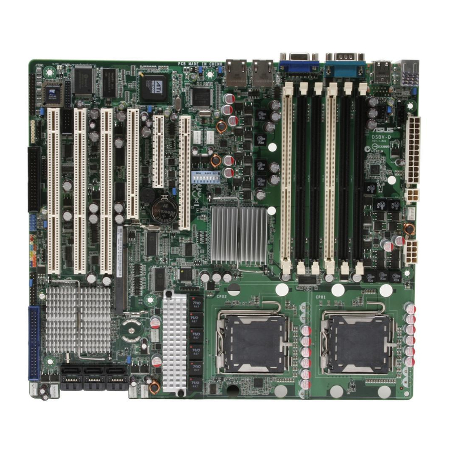
Page 26: Motherboard Layouts
2.2.4 Motherboard layouts DSBV-D ATXPWR1 PS/2 KBPWR1 PSUSMB1 T: Mouse B: Keyboard USBPW12 USB1 USB2 FBD_FAN1 FB-DIMM_12 (64/72 bit, 240-pin module) FB-DIMM_11 (64/72 bit, 240-pin module) FB-DIMM_10 (64/72 bit, 240-pin module) FB-DIMM_02 (64/72 bit, 240-pin module) FB-DIMM_01 (64/72 bit, 240-pin module) FB-DIMM_00 (64/72 bit, 240-pin module) RJ-45 (LAN1) -
Page 27: Layout Contents
DIP switches (DIP_SW1) Rear panel connectors PS/2 mouse port (green) PS/2 keyboard port (purple) USB 2.0 ports 1 and 2 Serial (COM1) port Video Graphics Adapter port LAN (RJ-45) ports ASUS DSBV-D Page 2-14 2-22 2-22 2-23 2-23 Page 2-24... - Page 28 Internal connectors Floppy disk drive connector (34-1 pin FLOPPY1) IDE connector (40-1 pin PRI_IDE) Serial ATA connectors (7-pin SATA1, SATA2, SATA3, SATA4, SATA5, SATA6 ) Hard disk activity LED connector (4-pin HDLED1) USB connector (10-1 pin USB34) Serial port connector (10-1 pin COM2) CPU and system fan connectors (4-pin CPU_FAN1/2, REAR_FAN1/2, FRNT_FAN1/2/3/4, FBD_FAN1) Power supply SMBus connector (5-pin PSUSMB1)
-
Page 29: Central Processing Unit (Cpu)
ASUS will shoulder the cost of repair only if the damage is shipment/transit-related. • Keep the cap after installing the motherboard. ASUS will process Return Merchandise Authorization (RMA) requests only if the motherboard comes with the cap on the LGA771 socket. - Page 30 Press the load lever with your thumb (A), then move it to the left (B) until it is released from the retention tab. Retention tab Load lever To prevent damage to the socket pins, do not remove the PnP cap unless you are installing a CPU.
- Page 31 Under the Advanced Menu, make sure that the item Hyper-Threading Technology is set to Enabled. The item appears only if you installed a CPU that supports Hyper-Threading Technology. Reboot the computer. ASUS DSBV-D ® Xeon™ CPUs in the 771-land package ®...
-
Page 32: Installing The Cpu Heatsink And Fan
2.3.2 Installing the CPU heatsink and fan ® The Intel Xeon™ processors require an Intel certified heatsink and fan assembly to ensure optimum thermal condition and performance. When you buy a boxed Intel CPU, the package includes the heatsink, fan, retention brackets, screws, thermal grease, installation manual, and other items that are necessary for CPU installation. - Page 33 CPU_FAN1 connector Repeat steps 1 to 3 to install the other heatsink if you have installed a second CPU, then connect the fan cable to the 4-pin connector labeled CPU_FAN2. ASUS DSBV-D 2-13...
-
Page 34: System Memory
FB-DIMMs into the DIMM sockets. • For optimum compatibility, we recommend that you obtain memory modules from the same vendor. Refer to the Qualified Vendors List on the ASUS web site. • This motherboard does not support memory modules made up of 128 Mb chips or double-rank x16 memory modules. - Page 35 • For better performance, same configuration DIMMs should be installed on the same slot number for each channel. For example, you may install the same type of DIMMs in DIMM_00, and DIMM_10. ASUS DSBV-D Ch:0 Slot/s to use DIMM_00 DIMM_00, DIMM_10...
-
Page 36: Memory Sparing Technology
2.4.3 Memory sparing technology ® The Intel 5000V chipset supports the memory sparing technology. Refer to the below sections: Memory Sparing : At configuration time, a DIMM rank is set aside to replace a defective DIMM rank. When the error rate for a failing DIMM rank reaches a pre-determined threshold, the memory sparing function will issue an interrupt and initiate a spare copy. - Page 37 Memory space 1024 MB Total Memory Two DIMM per channel (Single rank) Sparing Memory space (1024MB/1 Ranks) Sparing Memory space Total Memory ASUS DSBV-D Channel 0 DIMM_00 (1024MB/2 Ranks) Rank 1 Rank 0 (512 MB) (512 MB) 512 MB 512 MB...
- Page 38 Three DIMMs per channel (Dual ranks) Sparing Memory space Sparing Memory space Sparing Memory space Total Memory Three DIMMs per channel (Single ranks) Sparing Memory space Sparing Memory space Sparing Memory space Total Memory 2-18 Channel 0 DIMM_00 (1024/2 Ranks) Rank 0 Rank 1 (1024 MB)
-
Page 39: Installing A Dimm
DIMM. Support the DIMM lightly with your fingers when pressing the retaining clips. The DIMM might get damaged when it flips out with extra force. Remove the DIMM from the socket. ASUS DSBV-D FB-DIMM notch 2-19... -
Page 40: Installing The Optional Memcool Fb-Dimm Fan
2.4.6 Installing the optional MemCool FB-DIMM fan The FB-DIMMs generate heat during continued operation. To ensure optimum thermal condition and performance, install the optional MemCool FB-DIMM fan. To install the optional FB-DIMM fan: Locate the three FB-DIMM fan holes on the motherboard. Disengage the fan top cover from the fan base. - Page 41 Make sure the cables pass through the notch on the fan base as shown. Connect the fan cable to the black 4-pin connector labeled FBD_FAN1. ASUS DSBV-D 2-21...
-
Page 42: Uninstalling The Optional Memcool Fb-Dimm Fan
2.4.7 Uninstalling the optional MemCool FB-DIMM fan Unplug the fan cable. Grip the top cover clamps until the top cover hooks are released, then carefully lift the top cover while supporting the fan base with your free hand. Carefully lift the fan base. 2-22 Top cover clamp... -
Page 43: Expansion Slots
When using PCI cards on shared slots, ensure that the drivers support “Share IRQ” or that the cards do not need IRQ assignments. Otherwise, conflicts will arise between the two PCI groups, making the system unstable and the card inoperable. ASUS DSBV-D 2-23... -
Page 44: Interrupt Assignments
2.5.3 Interrupt assignments Standard interrupt assignments Priority — * These IRQs are usually available for ISA or PCI devices. 2-24 Standard Function System Timer Keyboard Controller Re-direct to IRQ#9 Communications Port (COM2)* Communications Port (COM1)* IRQ holder for PCI steering* Floppy Disk Controller Printer Port (LPT1)* System CMOS/Real Time Clock... -
Page 45: Pci-X Slots
The PCI-X slots support cards such as a LAN card, SCSI card, USB card, and other cards that comply with PCI 2.3 and PCI-X 1.0 specifications. PCI-X slot 2.5.5 DDR2 SODIMM socket The DDR2 SODIMM socket on the motherboard supports an ® ASUS Server Management Board 3 Series (ASMB3). SODIMM socket ASUS DSBV-D 2-25... -
Page 46: Pci Express X8 Slot (X4 Link)
2.5.6 PCI Express x8 slot (x4 link) The onboard PCI Express x8 slot provides x4 link to the ESB. This slot is designed for various server class high performance I/O add-on cards like SCSI RAID card, fiber-channel card, etc. PCI Express x8 slot 2.5.7 PCI Express x16 slot (x8 link) This motherboard supports PCI Express I/O cards that comply with the PCI... -
Page 47: Jumpers
Hold down the <Del> key during the boot process and enter BIOS setup to re-enter data. Except when clearing the RTC RAM, never remove the cap on CLRTC jumper default position. Removing the cap will cause system boot failure! DSBV-D Clear RTC RAM ASUS DSBV-D CLRTC1 Normal Clear CMOS (Default) - Page 48 LAN bandwidth setting (3-pin LAN_BW1) This jumper allows you to set the LAN bandwidth setting for more efficient IP load distribution. DSBV-D LAN bandwidth setting USB device wake-up (3-pin USBPW12, USBPW34) Set these jumpers to +5V to wake up the computer from S1 sleep mode (CPU stopped, DRAM refreshed, system running in low power mode) using the connected USB devices.
- Page 49 DSBV-D Keyboard power setting VGA controller setting (3-pin VGA_EN1) These jumpers allow you to enable or disable the onboard VGA controller. Set to pins 1-2 to activate the VGA feature. DSBV-D VGA setting ASUS DSBV-D KBPWR1 +5VSB (Default) VGA_EN1 Enable...
- Page 50 LAN controller setting (3-pin LAN_EN1) This jumper allows you to enable or disable the onboard Intel LAN controller. Set to pins 1-2 to activate the Gigabit LAN feature. DSBV-D LAN1_EN setting ® Intel 6321ESB SATA port S/W RAID setting (3-pin RAID_SEL1) This jumper allows you to select the Serial ATA RAID configuration utility to use when you create disk arrays.
- Page 51 Insert the floppy disk then turn on the system to update the BIOS. Shut down the system. Set the jumper back to pins 1-2. Turn on the system. DSBV-D BIOS recovery setting ASUS DSBV-D RECOVERY1 Normal BIOS Recovery (Default) 2-31...
-
Page 52: Connectors
Switch DIP switches (DIP_SW1) This switch allows you to set up the fan connections. Set the switch to ON if you are using a 4-pin fan (PWM fan) cable plug, or to OFF if you are using a 3-pin (PC fan) plug. DSBV-D DIP switches The following table shows the corresponding switch for each fan connector. -
Page 53: Connectors
Network (LAN) through a network hub. Refer to the table below for the LAN port LED indications. LAN port LED indications ACT/LINK LED Status Description No link GREEN Linked BLINKING Data activity ASUS DSBV-D SPEED LED Status Description 10 Mbps connection ORANGE 100 Mbps connection GREEN 1000 Mbps connection ACT/LINK SPEED... -
Page 54: Internal Connectors
2.8.2 Internal connectors Floppy disk drive connector (34-1 pin FLOPPY1) This connector is for the provided floppy disk drive (FDD) signal cable. Insert one end of the cable to this connector, then connect the other end to the signal connector at the back of the floppy disk drive. Pin 5 on the connector is removed to prevent incorrect cable connection when using a FDD cable with a covered Pin 5. - Page 55 DSBV-D SATA connectors Hard disk activity LED connector (4-pin HDLED1) This connector is used to connect to a hard disk drive active LED connector on the SCSI or RAID card. DSBV-D storage card activity LED connector ASUS DSBV-D SATA2 SATA1 RSATA_TXP2 RSATA_TXP1...
- Page 56 USB connector (10-1 pin USB34) This connector is for USB 2.0 ports. Connect the USB module cable to this connector, then install the module to a slot opening at the back of the system chassis. This USB connector complies with USB 2.0 specification that supports up to 480 Mbps connection speed.
- Page 57 Do not place jumper caps on the fan connectors! DSBV-D Fan connectors Power supply SMBus connector (5-pin PSUSMB1) This connector is for the power supply SMB cable, if your power supply supports the SMBus function. DSBV-D Power supply SMBus connector ASUS DSBV-D CPU_FAN1 CPU_FAN2 CPU_FAN1 FBD_FAN1 REAR_FAN1...
- Page 58 SSI power connectors (24-pin ATXPWR1, 8-pin ATX12V1, 4-pin ATX12V2) These connectors are for SSI power supply plugs. The power supply plugs are designed to fit these connectors in only one orientation. Find the proper orientation and push down firmly until the connectors completely fit. •...
- Page 59 11. Backplane SMBus connector (7-1 pin BPSMB1) This connector allows you to connect SMBus (System Management Bus) devices. Devices communicate with an SMBus host and/or other SMBus devices using the SMBus interface. DSBV-D BPSMB connector ASUS DSBV-D LPT1 BPSMB1 PIN1 PIN1...
- Page 60 12. Serial General Purpose Input/Output connector (6-1 pin SGPIO1) This connector is used to the SGPIO peripherals for the LSI MegaRAID SATA LED. DSBV-D SGPIO connector 13. System panel connector (20-1 pin PANEL1) This connector supports several chassis-mounted functions. The system panel connector is color-coded for easy connection. DSBV-D System panel connector •...
- Page 61 The LED blinks when the system is in the booting process until the operating system is loaded. Connect the message LED cable to this connector. • Non-Masked Interrupt button (Light blue 2-pin MNIBTN) This 2-pin connector is for the non-masked interrupt initiation. ASUS DSBV-D 2-41...
- Page 62 14. System panel auxiliary connector (20-2 pin AUX_PANEL1) This connector is for additional front panel features including front panel SMB, locator LED and switch, chassis intrusion, and LAN LEDs. DSBV-D System panel auxiliary connector Front panel SMB (6-1 pin FPSMB) These leads connect the front panel SMBus cable.
-
Page 63: Chapter 3: Powering Up
This chapter describes the power up sequence, and ways of shutting down the system. Powering up... - Page 64 Chapter summary Starting up for the first time ... 3-1 Turning off the computer ... 3-2 ASUS DSBV-D...
-
Page 65: Starting Up For The First Time
One continuous beep followed by short beeps Two short beeps At power on, hold down the <Delete> key to enter the BIOS Setup. Follow the instructions in Chapter 4. ASUS DSBV-D Error Memory module missing VGA controller failure PCI resource assignment error... -
Page 66: Turning Off The Computer
Turning off the computer 3.2.1 Using the OS shut down function If you are using Windows Click the Start button then click Shut Down... Make sure that the Shut Down option button is selected, then click the OK button to shut down the computer. The power supply should turn off after Windows If you are using Windows Click the Start button then select Turn Off Computer. -
Page 67: Chapter 4: Bios Setup
This chapter tells how to change the system settings through the BIOS Setup menus. Detailed descriptions of the BIOS parameters are also provided. BIOS setup... - Page 68 Chapter summary Managing and updating your BIOS ... 4-1 BIOS setup program ... 4-8 Main menu ... 4-12 Advanced menu ... 4-18 Server menu ... 4-38 Security menu ... 4-41 Boot menu ... 4-43 Exit menu ... 4-45 ASUS DSBV-D...
-
Page 69: Managing And Updating Your Bios
Phoenix Phlash16 BIOS Flash Utility (Updates the BIOS in DOS mode using a bootable floppy disk.) ASUS CrashFree BIOS 2 (To recover the BIOS using a bootable floppy disk when the BIOS file fails or gets corrupted.) ASUS Update (Updates the BIOS in Windows Refer to the corresponding sections for details on these utilities. -
Page 70: Updating The Bios Using The Phoenix Phlash16 Utility
The Basic Input/Output System (BIOS) can be updated using the Phoenix Phlash16 Utility. Follow these instructions to update the BIOS using this utility. Download the latest BIOS file from the ASUS web site. Rename the file to BIOS.WPH. Save the file to a floppy disk. -
Page 71: Asus Crashfree Bios 2 Utility
4.1.3 ASUS CrashFree BIOS 2 utility The ASUS CrashFree BIOS 2 is an auto recovery tool that allows you to restore the BIOS file when it fails or gets corrupted during the updating process. You can update a corrupted BIOS file using a floppy disk. - Page 72 Phoenix Phlash16 Utility Version 1.6.1.9 Copyright (c) Phoenix Technologies Ltd., 2005 Load Image File Verify interface information Backup system BIOS ROM Check flash memory type(s) Flash memory block: Save block Restore block Zero out block Erase block Program block Verify block Flash programming complete 30% Read in Identifying flash memory part type DO NOT shut down or reset the system while updating the BIOS! Doing so can...
-
Page 73: Asus Update Utility
Visit the ASUS website (www.asus.com) to download the latest BIOS file. 4.1.4 ASUS Update utility The ASUS Update is a utility that allows you to manage, save, and update the motherboard BIOS in Windows • Save the current BIOS file •... - Page 74 Updating the BIOS through the Internet To update the BIOS through the Internet: Launch the ASUS Update utility from the Windows > Programs > ASUS > ASUSUpdate > ASUSUpdate. The ASUS Update main window appears. Select Update BIOS from the Internet option from the drop-down menu, then click Next.
- Page 75 Updating the BIOS through a BIOS file To update the BIOS through a BIOS file: Launch the ASUS Update utility from the Windows > Programs > ASUS > ASUSUpdate > ASUSUpdate. The ASUS Update main window appears. Select Update BIOS from a file option from the drop-down menu, then click Next.
-
Page 76: Bios Setup Program
The BIOS setup screens shown in this section are for reference purposes only, and may not exactly match what you see on your screen. • Visit the ASUS website (www.asus.com) to download the latest BIOS file for this motherboard. Chapter 4: BIOS setup... -
Page 77: Bios Menu Screen
For selecting the exit options and loading default settings To select an item on the menu bar, press the right or left arrow key on the keyboard until the desired item is highlighted. ASUS DSBV-D Configuration fields PhoenixBIOS Setup Utility... -
Page 78: Legend Bar
4.2.3 Legend bar At the bottom of the Setup screen is a legend bar. The keys in the legend bar allow you to navigate through the various setup menus. The following table lists the keys found in the legend bar with their corresponding functions. Navigation Key Function <F1>... -
Page 79: Pop-Up Window
↑↓ Exit Select Menu →← 4.2.8 General help At the top right corner of the menu screen is a brief description of the selected item. ASUS DSBV-D PhoenixBIOS Setup Utility Security Boot Exit [04/19/2006] [15 : 30 : 36] [1.44/1.25 MB ”]... -
Page 80: Main Menu
Main menu When you enter the BIOS Setup program, the Main menu screen appears, giving you an overview of the basic system information. Refer to section “5.2.1 BIOS menu screen” for information on the menu screen items and how to navigate through them. Main Advanced System Date... -
Page 81: Ide Configuration
Help Select Item ↑↓ Exit Select Menu →← Parallel ATA [Enabled] Allows you to enable or disable the parallel ATA function. Configuration options: [Disabled] [Enabled] ASUS DSBV-D PhoenixBIOS Setup Utility [Normal] Change Values Enter Select Sub-Menu PhoenixBIOS Setup Utility [Enabled]... - Page 82 Serial ATA [Enabled] Allows you to enable or disable the Serial ATA function. Configuration options: [Disabled] [Enabled] SATA Controller Mode Option [Enhanced] Allows selection of the Serial ATA operation mode depending on the operating system (OS) that you installed. When you set this item to Enhanced Mode, Serial ATA and Parallel ATA devices are auto-detected and placed in native IDE mode.
-
Page 83: Ide Channel 0 Master/Slave
LBA mode disabled. Configuration options: [Disabled] [Enabled] 32 Bit I/O [Disabled] Enables or disables 32-bit data transfer. Configuration options: [Disabled] [Enabled] ASUS DSBV-D PhoenixBIOS Setup Utility [Auto] [Disabled] [Disabled]... -
Page 84: System Information
Select Item ↑↓ Exit Select Menu →← The items in this menu are non-user configurable. Model Name/Model ID Displays the ASUS internal model information. ASUS BIOS Displays the BIOS revision and build date. 4-16 PhoenixBIOS Setup Utility DSBV-D 8032A0 1004... - Page 85 None DIMM_10-- None DIMM_11-- None DIMM_12-- None Help Select Item ↑↓ Exit Select Menu →← ASUS DSBV-D PhoenixBIOS Setup Utility Change Values Enter Select Sub-Menu PhoenixBIOS Setup Utility Change Values Enter Select Sub-Menu Item Specific Help All items on this menu cannot be modified in user mode.
-
Page 86: Advanced Menu
Advanced menu The Advanced menu items allow you to change the settings for the CPU and other system devices. Take caution when changing the settings of the Advanced menu items. Incorrect field values can cause the system to malfunction. Main Advanced Server WARNING:... - Page 87 Set Max Ext CPUID = 3 [Disabled] Enable this item to boot legacy operating systems that cannot support CPUs with extended CPUID functions. Configuration options: [Disabled] [Enabled] Echo TPR [Disabled] Configuration options: [Disabled] [Enabled] Discrete MTRR Allocation [Disabled] Configuration options: [Disabled] [Enabled] ASUS DSBV-D 4-19...
- Page 88 Intel EIST support [Enabled] Enables or disables EIST support. Configuration options: [Disabled] [Enabled] The following screens appear when you install Intel Advanced Advanced Processor Options Multiprocessor Specification Numbers of Stop Grant Intel(R) Virtualization Technology Machine Checking Fast String Operations Compatible FPU Code Split Lock operations Thermal Management 2 C1 Enhanced Mode...
- Page 89 Enable this item to boot legacy operating systems that cannot support CPUs with extended CPUID functions. Configuration options: [Disabled] [Enabled] Echo TPR [Disabled] Configuration options: [Disabled] [Enabled] Discrete MTRR Allocation [Disabled] Configuration options: [Disabled] [Enabled] Intel EIST support [Enabled] Enables or disables EIST support. Configuration options: [Disabled] [Enabled] ASUS DSBV-D 4-21...
- Page 90 The following screens appear when you install Intel Advanced Advanced Processor Options Multiprocessor Specification Numbers of Stop Grant Intel(R) Virtualization Technology Machine Checking Fast String Operations Compatible FPU Code Split Lock operations Thermal Management 2 C1 Enhanced Mode No Execute Mode Mem Protection Adjacent Cache Line Prefetch Set Max Ext CPUID = 3 Echo TPR...
- Page 91 Enable this item to boot legacy operating systems that cannot support CPUs with extended CPUID functions. Configuration options: [Disabled] [Enabled] Echo TPR [Disabled] Configuration options: [Disabled] [Enabled] Discrete MTRR Allocation [Disabled] Configuration options: [Disabled] [Enabled] Intel EIST support [Enabled] Enables or disables EIST support. Configuration options: [Disabled] [Enabled] ASUS DSBV-D 4-23...
-
Page 92: Chipset Configuration
4.4.2 Chipset Configuration This menu shows the chipset configuration settings. Select an item then press <Enter> to display a pop-up menu with the configuration options. Advanced Crystal Beach Configure Enable SERR Signal Condition Demand Scrub Enable Patrol Scrub Enable 4GB PCI Hole Granularity Memory Branch Mode Branch 0 Rank Interleave Branch 0 Rank Sparing... - Page 93 Configuration options: [Disabled] [Enabled] FBDIMM(s) Thermal Throttling [Open Loop] Allows you to disable or set the thermal throttling control. Configuration options: [Open Loop] [Close Loop] [ASUS MemCool Fan] [Disabled] Open Loop Type [Best Performance] Allows you to select the Open Loop Type.
-
Page 94: Pci Configuration
4.4.3 PCI Configuration This menu shows the PCI configuration settings. Select an item then press <Enter> to display the configuration options. Advanced Reset Configuration Data Plug & Play OS Palette Snooping PCIE1 Slot PCIE2 Slot PCI3 Slot PCIX4 Slot PCIX5 Slot PCIX6 Slot Help Select Item ↑↓... - Page 95 Help Select Item ↑↓ Exit Select Menu →← Optional ROM Scan [Enabled] Allows you to enable or disable the device expansion ROM. Configuration options: [Enabled] [Disabled] ASUS DSBV-D PhoenixBIOS Setup Utility [Enabled] Change Values Enter Select Sub-Menu Item Specific Help Initialize device...
-
Page 96: Ich Usb Control Sub-Menu
4.4.4 ICH USB Control Sub-Menu The items in this menu allow you to display the USB configuration settings. Select an item then press <Enter> to display the configuration options. Advanced ICH USB Control Sub-Menu USB Function USB 2.0 Controller Legacy USB Support: Help Select Item ↑↓... -
Page 97: Peripheral Devices Configuration
Allows you to set the mode for COM2 port. Configuration options: [Normal] [IR] [ASK-IR] Base I/O address [2F8] Allows you to select the base I/O address for COM2 port. Configuration options: [3F8] [2F8] [3E8] [2E8] ASUS DSBV-D PhoenixBIOS Setup Utility [Enabled] [3F8] [IRQ 4]... - Page 98 Interrupt [IRQ 3] Allows you to set the interrupt for COM2 port. Configuration options: [IRQ 3] [IRQ 4] Parallel port [Enabled] Allows you to configure the parallel port. Configuration options: [Disabled] [Enabled] [Auto] Base I/O address [378] Allows you to select the base I/O address for the parallel port. Configuration options: [378] [278] [3BC] Interrupt [IRQ 7] Allows you to set the interrupt for the parallel port.
-
Page 99: Acpi Configuration
Allows you to enable or disable the headless operation mode through ACPI. Configuration options: [Disabled] [Enabled] ACPI EMS Support [Disabled] Allows you to enable or disable the ACPI EMS support. Configuration options: [Disabled] [Enabled] ASUS DSBV-D PhoenixBIOS Setup Utility [ACPI v1.0] [Disabled] [Disabled]... -
Page 100: Power On Configuration
4.4.7 Power On Configuration This menu shows the power configuration settings. Select an item then press <Enter> to display the configuration options. Advanced Restore on AC Power Loss Power On By PS/2 Keyboard Power On By PS/2 Mouse Power On By PME# Power On By RTC Alarm Help Select Item... -
Page 101: Hardware Monitor
FRN_FAN2 Speed FRN_FAN3 Speed FRN_FAN4 Speed REAR_FAN1 Speed REAR_FAN2 Speed Smart Fan Control Help Select Item ↑↓ Exit Select Menu →← ASUS DSBV-D PhoenixBIOS Setup Utility C/102 C/84 C/32 C/32 C/102 C/84 2925 RPM [Smart Fan II] Change Values Enter... - Page 102 Scroll down to display more items: Advanced CPU1 Domain 0 Target Temperature CPU1 Domain 1 Target Temperature CPU2 Domain 0 Target Temperature CPU2 Domain 1 Target Temperature SYSTEM1 Target Temperature SYSTEM2 Target Temperature FBD_FAN1 Speed VCORE0 Voltage VCORE1 Voltage +1.5V +1.8V +12V +5VSB...
- Page 103 Configuration options: [Disabled] [Smart Fan] [Smart Fan II] CPU1/2 Target Temperature Allows you to set the target CPU temperature at which the CPU fan will start running if the fan is not yet turned on. Configuration options: [54]~[76] ASUS DSBV-D PhoenixBIOS Setup Utility C/102 C/84...
- Page 104 SYSTEM1/2 Target Temperature Allows you to set the target sytem temperature at which the system fan will start running if the fan is not yet turned on. Configuration options: [39]~[60] FBD_FAN1 Speed, VCORE0/1 Voltage, VTT, +1.5V, +1.8V, +3V, +12V, +5V, +5VSB, VBAT These fields show the auto-detected values and are not user-configurable.
- Page 105 Allows you to set the target sytem temperature at which the system fan will start running if the fan is not yet turned on. Configuration options: [39]~[60] FBD_FAN1 Speed, VCORE0/1 Voltage, VTT, +1.5V, +1.8V, +3V, +12V, +5V, +5VSB, VBAT These fields show the auto-detected values and are not user-configurable. ASUS DSBV-D 4-37...
-
Page 106: Server Menu
Server menu This Server menu items allow you to customize the server features. Main Advanced Server Console Redirection DMI Event Logging Help Select Item ↑↓ Exit Select Menu →← 4.5.1 Console Redirection Main Advanced Server Com Port Address Help Select Item ↑↓... - Page 107 Allows you to set the number of video pages to allocate for console redirection when the video hardware is not available. Press <-> or <+> to set the value, or enter the value using the numeric keypad. Configuration options: [1] ~ [8] ASUS DSBV-D 4-39...
-
Page 108: Dmi Event Logging
4.5.2 DMI Event Logging Main Advanced Server Event log validity Event log capacity View DMI event log Event Logging ECC Event Logging Mark DMI events as read Clear all DMI event logs Help Select Item ↑↓ Exit Select Menu →← Event log validity, Event log capacity Displays the auto-detected system information. -
Page 109: Security Menu
Password Check Password Lock Mode Removable Device Boot Enter Current Password Flash Write Enter New Password Confirm New Password Help Select Item ↑↓ Exit Select Menu →← ASUS DSBV-D PhoenixBIOS Setup Utility Security Boot Exit Clear Clear [Enter] [Enter] [Setup] [Disabled] [Enabled] [Enabled]... - Page 110 In the Enter current password field, type in your current password. Press <Enter>. The cursor moves to the next field, Enter new password. Press <Enter>. Do not type anything in this field. The cursor moves to the next field, Confirm new password. Press <Enter>.
-
Page 111: Boot Menu
<x> exclude or include the device to boot. <Shift + 1> enable or disable the device. <1 - 4> load default boot sequence. ASUS DSBV-D PhoenixBIOS Setup Utility Security Boot Exit Change Values Enter... -
Page 112: Boot Features
4.7.2 Boot Features Main Advanced Server Quick Boot Full Logo Display Bootup Num-Lock PS/2 Mouse Summary screen: POST Errors SETUP prompt Interrupt 19 Capture Help Select Item ↑↓ Exit Select Menu →← Quick Boot [Enabled] Enabling this item allows the BIOS to skip some power on self tests (POST) while booting to decrease the time needed to boot the system. -
Page 113: Exit Menu
• select [Yes], then press <Enter> to discard your changes and exit. • select [No], then press <Enter>, or simply press <Esc>, to cancel the command and return to the Exit menu. ASUS DSBV-D PhoenixBIOS Setup Utility Security Boot Exit... -
Page 114: Discard Changes
Discard Changes Select this option to discard the changes that you made, and restore the previously saved values. When a confirmation window appears: • select [Yes], then press <Enter> to discard any changes and load the previously saved values. • select [No], then press <Enter>, or simply press <Esc>, to cancel the command and return to the Exit menu. - Page 115 This chapter provides instructions for setting up, creating, and configuring RAID sets using the available utilities. RAID configuration...
- Page 116 Chapter summary Setting up RAID ... 5-1 LSI Logic Embedded SATA RAID Setup Utility ... 5-4 ® Intel Matrix Storage Manager Option ROM Utility ... 5-31 Global Array Manager ... 5-39 ASUS DSBV-D...
-
Page 117: Setting Up Raid
If you want to boot the system from a hard disk drive included in a created RAID set, copy first the RAID driver from the support CD to a floppy disk before you install an operating system to the selected hard disk drive. ASUS DSBV-D Matrix Storage Manager. These utilities support SATA ®... -
Page 118: Installing Hard Disk Drives
5.1.2 Installing hard disk drives The motherboard supports Serial ATA for RAID set configuration. For optimal performance, install identical drives of the same model and capacity when creating a disk array. To install the SATA hard disks for RAID configuration: Install the SATA hard disks into the drive bays following the instructions in the system user guide. -
Page 119: Lsi Logic Embedded Sata Raid Setup Utility
At the bottom of the screen is the legend box. The keys on the legend box allow you to navigate through the setup menu options or execute commands. The keys on the legend box vary according to the menu level. ASUS DSBV-D... -
Page 120: Creating A Raid 0 Or Raid 1 Set
Menu Configure Initialize Objects Rebuild Check Consistency 5.2.1 Creating a RAID 0 or RAID 1 set The LSI Logic Embedded SATA RAID Setup Utility allows you to create a RAID 0 or RAID 1 set using two types of configurations: Easy and New. In Easy Configuration, the logical drive parameters are set automatically including the size and stripe size (RAID 1 only). - Page 121 ONLIN A[X]-[Y], where X is the array number, and Y is the drive number. The information of the selected hard disk drive displays at the bottom of the screen. Select all the drives required for the RAID set, then press <Enter>. The configurable array appears on screen. ASUS DSBV-D...
- Page 122 Press <F10>, select the configurable array, then press <SpaceBar>. Press <F10> again, the logical drive information appears including a Logical Drive menu that allows you to change the logical drive parameters. Chapter 5: RAID configuration...
- Page 123 When creating a RAID 1 set, select DWC from the Logical Drive menu, then press <Enter>. When creating a RAID 0 set, proceed to step 10. Select On to enable the Disk Write Cache setting, then press <Enter>. Enabling DWC can improve the performance, but with the risk of data loss. ASUS DSBV-D...
- Page 124 10. When finished setting the selected logical drive configuration, select Accept from the menu, then press <Enter>. 11. When finished setting the selected logical drive configuration, select Accept from the menu, then press <Enter>. 12. Follow steps 5 to 10 to configure additional logical drives. 13.
- Page 125 Follow steps 3 to 7 of the previous section. Select Size from the Logical Drive menu, then press <Enter>. Key-in the desired logical drive size, then press <Enter>. Follow steps 8 to 13 of the previous section to create the RAID set. ASUS DSBV-D...
-
Page 126: Creating A Raid 10 Set
5.2.2 Creating a RAID 10 set You can create a RAID 10 set using four identical hard disk drives. To create a RAID 10 set using the Easy Configuration option: From the utility main menu, highlight Configure, then press <Enter>. Use the arrow keys to select Easy Configuration, then press <Enter>. - Page 127 Select all the drives required for the RAID 10 set, then press <Enter>. The configurable array appears on screen. Press <F10>, select the configurable array, then press <SpaceBar>. ASUS DSBV-D 5-11...
- Page 128 Press <F10> again, the logical drive information appears including a Logical Drive menu that allows you to change the logical drive parameters. Select RAID from the Logical Drive menu, then press <Enter>. Select RAID 10 from the menu, then press <Enter>. You need at least four identical hard disk drives when creating a RAID 10 set.
- Page 129 10. When finished setting the selected logical drive configuration, select Accept from the menu, then press <Enter>. 11. When prompted, save the configuration, then press <Esc> to return to the Management Menu. ASUS DSBV-D 5-13...
-
Page 130: Adding Or Viewing A Raid Configuration
5.2.3 Adding or viewing a RAID configuration You can add a new RAID configuration or view an existing configuration using the View/Add Configuration command. Adding a new RAID configuration To add a new RAID configuration: From the Management Menu, highlight Configure, then press <Enter>. Use the arrow keys to select View/Add Configuration, then press <Enter>. - Page 131 Press <F10>, select the configurable array, then press <SpaceBar>. Press <F10> again, and select RAID from the Logical Drive menu, then press <Enter>. Select the RAID level from the menu, then press <Enter>. ASUS DSBV-D 5-15...
- Page 132 Follow steps 8 to 12 of the Creating a RAID set: Using Easy Configuration section. When prompted, save the configuration, then press <Esc> to return to the Management Menu. Follow steps 8 to 13 of the Creating a RAID set: Using Easy Configuration section to add the new RAID configuration.
-
Page 133: Initializing The Logical Drives
From the Management Menu, highlight Initialize, then press <Enter>. The screen displays the available RAID set(s) and prompts you to select the logical drive to initialize. Use the arrow keys to select the logical drive from the Logical Drive selection, then press <Enter>. ASUS DSBV-D 5-17... - Page 134 When prompted, press the <SpaceBar> to select Yes from the Initialize? dialog box, then press <Enter>. You may also press <F10> to initialize the drive without confirmation. Initializing a logical drive(s) erases all data on the drive. A progress bar appears on screen. If desired, press <Esc> to abort initialization.
- Page 135 When initialization is completed, press <Esc>. Using the Objects command To initialize the logical drives using the Objects command: From the Management Menu, highlight Objects, then press <Enter>. ASUS DSBV-D 5-19...
- Page 136 Select Logical Drive from the Objects sub-menu, then press <Enter>. Select the logical drive to initialize from the Logical Drives sub-menu, then press <Enter>. Select Initialize from the pop-up menu, then press <Enter> to start initialization. 5-20 Chapter 5: RAID configuration...
- Page 137 When prompted, press the <SpaceBar> to select Yes from the Initialize? dialog box, then press <Enter>. You may also press <F10> to initialize the drive without confirmation. A progress bar appears on screen. If desired, press <Esc> to abort initialization. When initialization is completed, press <Esc>. ASUS DSBV-D 5-21...
-
Page 138: Rebuilding Failed Drives
5.2.5 Rebuilding failed drives You can manually rebuild failed hard disk drives using the Rebuild command in the Management Menu. To rebuild a failed hard disk drive: From the Management Menu, highlight Rebuild, then press <Enter>. The PHYSICAL DRIVES SELECTION MENU displays the available drives connected to the SATA ports. - Page 139 After selecting the drive to rebuild, press <F10>. The indicator for the selected drive now shows RBLD. When prompted, press <Y> to to rebuild the drive. When rebuild is complete, press any key to continue. ASUS DSBV-D 5-23...
-
Page 140: Checking The Drives For Data Consistency
5.2.6 Checking the drives for data consistency You can check and verify the accuracy of data redundancy in the selected logical drive. The utility can automatically detect and/or detect and correct any differences in data redundancy depending on the selected option in the Objects > Adapter menu. - Page 141 • Continue - Continues the consistency check. • Abort - Aborts the consistency check. When you restart checking, it continues from zero percent. When checking is complete, press any key to continue. ASUS DSBV-D 5-25...
- Page 142 Using the Objects command To check data consistency using the Objects command: From the Management Menu, select Objects, then select Logical Drive from the menu. Use the arrow keys to select the logical drive you want to check, then press <Enter>.
-
Page 143: Deleting A Raid Configuration
From the Management Menu, select Configure > Clear Configuration, then press <Enter>. When prompted, press the <SpaceBar> to select Yes from the Clear Configuration? dialog box, then press <Enter>. The utility clears the current array. Press any key to continue. ASUS DSBV-D 5-27... -
Page 144: Selecting The Boot Drive From A Raid Set
5.2.8 Selecting the boot drive from a RAID set You must have created a new RAID configuration before you can select the boot drive from a RAID set. Refer to the Creating a RAID set: Using New Configuration section for details. To select the boot drive from a RAID set: From the Management Menu, select Configure >... -
Page 145: Enabling The Writecache
To enable WriteCache: From the Management Menu, select Objects > Adapter, then press <Enter> to display the adapter properties. Select WriteCache, then press <Enter> to turn the option On (enabled). When finished, press any key to continue. ASUS DSBV-D 5-29... -
Page 146: Intel ® Matrix Storage Manager Option Rom Utility
Intel Option ROM Utility ® The Intel Matrix Storage Manager Option ROM utility allows you to create RAID 0, RAID 1, RAID 0+1, and RAID 5 set(s) from Serial ATA hard disk drives. ® To enter the Intel Matrix Storage Manager Option ROM Utility: Turn on the system after installing all Serial ATA hard disk drives. -
Page 147: Creating A Raid 0 Set (Stripe)
Select 2 to 4 disks to use in creating the volume. [ ↑↓ ]-Previous/Next Use the up/down arrow key to highlight a drive, then press <Space> to select. A small triangle marks the selected drive. Press <Enter> after completing your selection. ASUS DSBV-D CREATE ARRAY MENU Name: Volume0 RAID0(Stripe) - Page 148 Use the up/down arrow key to select the stripe size for the RAID 0 array, then press <Enter>. The available stripe size values range from 4 KB to 128 KB. The default stripe size is 128 KB. A lower stripe size is recommended for server systems. A higher stripe size is recommended for multimedia computer systems used mainly for audio and video editing.
-
Page 149: Creating A Raid 1 Set (Mirror)
Highlight RAID Level, press the up/down arrow key to select |RAID 1 (Mirror), then press <Enter>. Follow steps 4 to 5 and 7 to 9 of the previous section to create the RAID 1 set. ASUS DSBV-D CREATE ARRAY MENU Name: Volume1... -
Page 150: Creating A Raid 10 Set (Stripe + Mirror)
5.3.3 Creating a RAID 10 set (Stripe + Mirror) To create a RAID 10 set: From the utility main menu, select 1. Create RAID Volume, then press <Enter>. This screen appears. Intel(R) Matrix Storage Manager Option ROM v5.0.0.1032 ESB2 wRAID5 Copyright(C) 2003-05 Intel Corporation. -
Page 151: Creating A Raid 5 Set (Parity)
Highlight RAID Level, press the up/down arrow key to select |RAID 10 (RAID0+1), then press <Enter>. Follow steps 4 to 9 of section “5.3.1 Creating a RAID 0 set (striped)” to create the RAID 5 set. ASUS DSBV-D CREATE ARRAY MENU Name: Volume1... -
Page 152: Deleting A Raid Set
5.3.5 Deleting a RAID set Take caution when deleting a RAID set. You will lose all data on the hard disk drives when you delete a RAID set. To delete a RAID set: From the utility main menu, select 2. Delete RAID Volume, then press <Enter>... -
Page 153: Resetting Disks To Non-Raid
From the utility main menu, select 4. Exit, then press <Enter>. This window appears. Are you sure you want to exit? (Y/N): Press <Y> to exit or press <N> to return to the utility main menu. ASUS DSBV-D RESET RAID DATA Serial # Size XXXXXXXX XX.XGB Member Disk... -
Page 154: Global Array Manager
Global Array Manager You may also create a RAID set(s) in Windows Global Array Manager (GAM) application. The GAM application is available from the motherboard support CD. Refer to the GAM user guide in the motherboard support CD for details. 5-38 ®... -
Page 155: Chapter 6: Driver Installation
This chapter provides instructions for installing the necessary drivers for different system components. Driver installation... - Page 156 Chapter summary RAID driver installation ... 6-1 Intel chipset software installation ... 6-11 LAN driver installation ... 6-14 VGA driver installation... 6-18 ASUS DSBV-D...
-
Page 157: Raid Driver Installation
Create INTEL 6321 LSI MegaRAID for Win2k Driver Disk Create INTEL 6321 LSI MegaRAID for WinXP/Win2k3 32 bit Driver Disk Create INTEL 6321 LSI MegaRAID for WinXP/Win2k3 64 bit Driver Disk Create the emergent BIOS Recovery diskette H) ESB2 ASF firmware update Please choose A TO H: ASUS DSBV-D ® 2000/XP... -
Page 158: Installing The Raid Controller Driver
Place a blank, high-density floppy disk to the floppy disk drive, then select the type of RAID driver disk you want to create by typing the number before the option Press <Enter>. Follow screen instructions to create the driver disk. For systems with Red Hat Makedisk menu, explore the support CD and copy the RAID driver disk from the following path:... - Page 159 Logic Embedded SATA RAID (DSBV-D). ® The Windows 2000/2003 Setup loads the RAID controller drivers from the RAID driver disk. When prompted, press <Enter> to continue installation. Setup then proceeds with the OS installation. Follow screen instructions to continue. ASUS DSBV-D...
- Page 160 To an existing Windows To install the RAID controller driver on an existing Windows Restart the computer, then log in with Administrator privileges. ® Windows automatically detects the RAID controller and displays a New Hardware Found window. Click Cancel. Right-click the My Computer icon on the Windows Properties from the menu.
- Page 161 Click the “+” sign before the item SCSI and RAID controllers. Right-click the RAID controller driver item, then select Properties from the menu. Click the Driver tab, then click the Driver Details button to display the RAID controller drivers. Click OK when finished. ASUS DSBV-D ® desktop , then select...
- Page 162 ® Red Hat Enterprise ver. 3.0 ® To install the Intel ESB2E LSI Logic Embedded SATA RAID controller driver when ® installing Red Hat Enterprise ver. 3.0 OS: Boot the system from the Red Hat At the boot: , type linux dd , then press <Enter>. ®...
- Page 163 Select Yes using the <Tab> key when asked if you have the driver disk. Press <Enter> Select fd0 using the <Tab> key when asked to select the driver disk source. Press <Tab> to move the cursor to OK, then press <Enter>. ASUS DSBV-D...
- Page 164 When prompted, insert the Red Hat the floppy disk drive, select OK, then press <Enter>. The drivers for the RAID controller are installed to the system. Follow screen instructions to continue the OS installation. ® Enterprise ver. 3.0 RAID driver disk to Chapter 6: Driver installation...
- Page 165 To install the RAID controller driver when installing SuSE Linux OS: Boot the system from the SuSE Installation CD. Select Installation from the Boot Options menu, then press <Enter>. A message instructs you to prepare the RAID driver disk. Press <F6>. ASUS DSBV-D...
- Page 166 When prompted, insert the RAID driver disk to the floppy disk drive, then press <Enter>. When prompted, select the floppy disk drive (fd0) as the driver update medium, select OK, then press <Enter>. The drivers for the RAID controller are installed to the system. 6-10 Chapter 6: Driver installation...
-
Page 167: Intel Chipset Software Installation
Insert the motherboard/system support CD to the optical drive. The support CD automatically displays the Drivers menu if Autorun is enabled in your computer. Click the item Intel(R) Chipset Software Installation Utility from the menu. ASUS DSBV-D ® chipset software on a Windows XP/2000 / ®... - Page 168 The Intel(R) Chipset Software Installation Utility window appears. Follow the screen instructions to complete installation. Select Yes to accept the terms of the License Agreement and continue the process. 6-12 Chapter 6: Driver installation...
- Page 169 Read the Readme File Information and press Next to activate the installation. After completing the installation, click Finish to restart the computer. ASUS DSBV-D 6-13...
-
Page 170: Lan Driver Installation
LAN driver installation This section provides the instructions on how to install Intel drivers. 6.3.1 Windows XP/2000/Server 2003 ® To install the Intel Gigabit LAN controller driver on a Windows 2003 OS: Restart the computer, and then log on with Administrator privileges. Insert the motherboard/system support CD to the optical drive. - Page 171 Click the Install Drivers option to begin installation. Click Next button when the Intel InstallShield Wizard window appears. ASUS DSBV-D ® PRO Network Connections – 6-15...
- Page 172 Select the “I accept the terms in the license agreement” and then click the Next button. Press the Complete and click Next button to fully install the driver, Intel PROSet for Windows Device Manager and Advanced Networking Services. 6-16 ® Chapter 6: Driver installation...
-
Page 173: Red Hat/Suse Linux
Change to the driver src directory. cd e1000-x.x.x/src/ Use the command “makeinstall” to compile the driver module. makeinstall After reboot the system, please refer to Linux distribution documentation to configure the network protocol and IP address. ASUS DSBV-D ® LAN controller base driver for 6-17... -
Page 174: Vga Driver Installation
VGA driver installation This section provides instructions on how to install the ATI Adapter (VGA) driver. 6.4.1 Windows 2000/Server 2003 You need to manually install the ATI® ES1000 VGA driver on a Windows 2000 / Server 2003 operating system. To install the ATI® ES1000 VGA driver: Restart the computer, then log on with Administrator privileges. - Page 175 The ATI Software window appears. Follow the screen instructions to complete installation. Select Yes to accept the terms of the License Agreement and continue the process. ASUS DSBV-D 6-19...
- Page 176 Press the After completing the installation, restart the computer. 6-20 button to activate quick installation. Chapter 6: Driver installation...
-
Page 177: Management Applications And Utilities Installation
The contents of the support CD are subject to change at any time without notice. Visit the ASUS website (www.asus.com) for updates. 6.5.1 Running the support CD Place the support CD to the optical drive. -
Page 178: Management Software Menu
Click an item to install. 6.5.5 Contact information Click the Contact tab to display the ASUS contact information. You can also find this information on the inside front cover of this user guide. 6-22 ASUS Remote Console... - Page 179 This appendix includes additional information that you may refer to when configuring the motherboard. Reference information...
-
Page 180: A.1 Dsbv-D Block Diagram
Appendix summary DSBV-D block diagram ...A-1 ASUS DSBV-D... -
Page 181: Dsbv-D Block Diagram
DSBV-D block diagram x16 slot PCIE1 x8 slot PCIE2 PCIX 133/100 PCIX4 PCIX5 PCIX6 Kumeran Gilgal ASUS DSBV-D Xeon5000/ Xeon5100; 5300 1333 FSB 5000V 6321ESB S/W RAID 0, 1, 10 6 x SATA FBDx3 FBDx3 PCI 33 PCI3 ES1000 1 x IDE... -
Page 182: Phlash16.Exe And Memory Managers
PHLASH16.EXE and memory managers Phlash16 may fail if your system is using memory managers, in which case the utility will display the following message: Memory manager error message Cannot flash if Memory Managers (e.g. EMM386) present If you see this message after you execute Phlash16, you must disable the memory manager on your system.