Table of Contents
Advertisement
Advertisement
Table of Contents

Related Manuals for Asus AT3N7A-I


Summary of Contents for Asus AT3N7A-I
- Page 1 AT3N7A-I...
- Page 2 Product warranty or service will not be extended if: (1) the product is repaired, modified or altered, unless such repair, modification of alteration is authorized in writing by ASUS; or (2) the serial number of the product is defaced or missing.
-
Page 3: Table Of Contents
Contents Notices ... v Safety information ... vi About this guide ... vii AT3N7A-I specifications summary ... viii Chapter 1: Product introduction Before you proceed ... 1-1 Motherboard overview ... 1-2 1.2.1 Motherboard layout ... 1-2 1.2.2 Layout contents ... 1-2 Central Processing Unit (CPU) ... - Page 4 ACPI 2.0 Support ...2-11 ACPI APIC Support ...2-11 APM Configuration ...2-11 Hardware Monitor ...2-11 Boot Device Priority ... 2-12 Boot Settings Configuration ... 2-12 Security ... 2-13 ASUS EZ Flash 2 ... 2-14 Express Gate ... 2-15 AI NET 2... 2-15...
-
Page 5: Notices
Complying with the REACH (Registration, Evaluation, Authorisation, and Restriction of Chemicals) regulatory framework, we published the chemical substances in our products at ASUS REACH website at http://green.asus.com/english/REACH.htm. DO NOT throw the motherboard in municipal waste. This product has been designed to enable proper reuse of parts and recycling. -
Page 6: Safety Information
Safety information Electrical safety • To prevent electric shock hazard, disconnect the power cable from the electric outlet before relocating the system. • When adding or removing devices to or from the system, ensure that the power cables for the devices are unplugged before the signal cables are connected. If possible, disconnect all power cables from the existing system before you add a device. -
Page 7: About This Guide
Refer to the following sources for additional information and for product and software updates. ASUS websites The ASUS website provides updated information on ASUS hardware and software products. Refer to the ASUS contact information. Optional documentation Your product package may include optional documentation, such as warranty flyers, that may have been added by your dealer. -
Page 8: At3N7A-I Specifications Summary
- 2 x 240-pin DIMM sockets support maximum 4GB unbuffered non-ECC 800/667 MHz DDR2 memory modules Refer to www.asus.com or this user manual for the Memory QVL (Qualified Vendors Lists). ** When you install a total memory of 4GB capacity... - Page 9 AT3N7A-I specifications summary Rear panel ports Internal connectors BIOS features Accessories Support DVD contents Form Factor *Specifications are subject to change without notice. 1 x PS/2 Keyboard port 1 x Bluetooth adapter 1 x eSATA port 2 x S/PDIF out ports (Optical & Coaxial)
-
Page 10: Chapter 1: Product Introduction
Chapter 1 Product introduction Thank you for buying an ASUS AT3N7A-I motherboard! ® Before you start installing the motherboard, and hardware devices on it, check the items in your motherboard package. Refer to page ix for the list of accessories. -
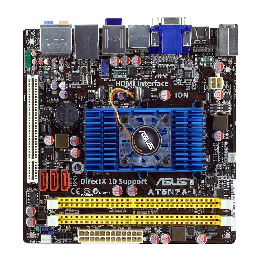
Page 11: Motherboard Overview
Motherboard overview 1.2.1 Motherboard layout Ensure that you install the motherboard into the chassis in the correct orientation. The edge with external ports goes to the rear part of the chassis. Place this side towards the rear of the chassis. Place four screws into the holes indicated by circles to secure the motherboard to the chassis. -
Page 12: Central Processing Unit (Cpu)
System memory 1.4.1 Overview The motherboard comes with two Double Data Rate 2 (DDR2) Dual Inline Memory Modules (DIMM) sockets. The figure illustrates the location of the DDR2 DIMM sockets: ASUS AT3N7A-I Atom™ 330 processor and a ® Channel Sockets... -
Page 13: Memory Configurations
• This motherboard does not support DIMMs made up of 256 megabits (Mb) chips or less. This motherboard supports up to 4GB on Windows Vista x64 editions. You may install a maximum of 2GB DIMMs on each slot. AT3N7A-I Motherboard Qualified Vendors Lists (QVL) DDR2-667 MHz capability Size Vendor Part No. - Page 14 Kingston KVR800D2N5/2G(low profile)DS 2048MB Kingston KVR800D2N6/2G(low profile)DS 4096MB Kingston KVR800D2N6/4G 2048MB Micron MT16HTF25664AY-800G1 1024MB OCZ2P800R22GK 1024MB OCZ2RPR8002GK ASUS AT3N7A-I Chip SS/DS Chip NO. Brand Heat-Sink Package VDATA VD29608A8A-25EG80813 N/A Hynix Heat-Sink Package Heat-Sink Package Apacer AM4B5708JQJS8E0751C 5 Apacer AM4B5808FEWS8E0909C5 Apacer...
- Page 15 • A*: Supports one module inserted into either slot as the single-channel memory configuration. • B*: Supports one pair of modules inserted into both the yellow slots as one pair of dual-channel memory configuration. Visit the ASUS website at www.asus.com for the latest QVL. Chip Part No. SS/DS...
-
Page 16: Expansion Slot
Assign an IRQ to the card. Install the software drivers for the expansion card. 1.5.3 PCI slot The PCI slot supports cards such as a LAN card, SCSI card, USB card, and other cards that comply with PCI specifications. ASUS AT3N7A-I... -
Page 17: Jumpers
Jumpers Clear RTC RAM (3-pin CLRTC) This jumper allows you to clear the Real Time Clock (RTC) RAM in CMOS. You can clear the CMOS memory of date, time, and system setup parameters by erasing the CMOS RTC RAM data. The onboard button cell battery powers the RAM data in CMOS, which include system setup information such as system passwords. -
Page 18: Connectors
• When Windows which will provide the complete Bluetooth functions. Download the latest Bluetooth driver from the ASUS support wedsite at http://support.asus.com. LAN (RJ-45) port. This port allows Gigabit connection to a Local Area Network (LAN) through a network hub. Refer to the table below for the LAN port LED indications. - Page 19 Line Out port (lime). This port connects to a headphone or a speaker. In the 4, 6 and 8-channel configurations, the function of this port becomes Front Speaker Out. Microphone port (pink). This port connects to a microphone. Side Speaker Out port (gray). This port connects to the side speakers in the 8-channel audio configuration.
-
Page 20: Internal Connectors
The system may become unstable or may not boot up if the power is inadequate. • If you are uncertain about the minimum power supply requirement for your system, refer to the Recommended Power Supply Wattage Calculator at http://support.asus. com/PowerSupplyCalculator/PSCalculator.aspx?SLanguage=en-us for details. ASUS AT3N7A-I... - Page 21 Serial ATA connectors (7-pin SATA1, SATA2, SATA3) These connectors are for the Serial ATA signal cables for Serial ATA 3Gb/s hard disk drives and optical disk drives. The Serial ATA 3Gb/s is backward compatible with the Serial ATA 1.5Gb/s specification. The data transfer rate of the Serial ATA 3Gb/s is faster than the standard parallel ATA (133 MB/s).
- Page 22 The signal is then generated as a chassis intrusion event. By default, the pin labeled “Chassis Signal” and “Ground” are shorted with a jumper cap. Remove the jumper caps only when you intend to use the chassis intrusion detection feature. ASUS AT3N7A-I 1-13...
- Page 23 CPU, power, and chassis fan connectors (3-pin CPU_FAN, 3-pin PWR_FAN, 3-pin CHA_FAN) The fan connectors support cooling fans of 350 mA~2000 mA (24 W max.) or a total of 1 A~3.48 A (41.76 W max.) at +12V. Connect the fan cables to the fan connectors on the motherboard, ensuring that the black wire of each cable matches the ground pin of the connector.
-
Page 24: System Panel Connector
Pressing the power switch for more than four seconds while the system is ON turns the system OFF. • Reset button (2-pin RESET) This 2-pin connector is for the chassis-mounted reset button for system reboot without turning off the system power. ASUS AT3N7A-I 1-15... -
Page 25: Software Support
The contents of the Support DVD are subject to change at any time without notice. Visit the ASUS website at www.asus.com for updates. To run the Support DVD Place the Support DVD to the optical drive. -
Page 26: Chapter 2: Bios Information
BIOS in the future. Copy the original motherboard BIOS using the ASUS Update utility. 2.1.1 ASUS Update utility The ASUS Update is a utility that allows you to manage, save, and update the motherboard BIOS in Windows environment. ®... -
Page 27: Asus Ez Flash 2
Follow the onscreen instructions to complete the updating process. 2.1.2 ASUS EZ Flash 2 The ASUS EZ Flash 2 feature allows you to update the BIOS without using an OS-based utility. Before you start using this utility, download the latest BIOS file from the ASUS website at www.asus.com. -
Page 28: Asus Crashfree Bios
2.1.3 ASUS CrashFree BIOS The ASUS CrashFree BIOS is an auto recovery tool that allows you to restore the BIOS file when it fails or gets corrupted during the updating process. You can restore a corrupted BIOS file using the motherboard support DVD or a removable device that contains the updated BIOS file. -
Page 29: Bios Setup Program
• The BIOS setup screens shown in this section are for reference purposes only, and may not exactly match what you see on your screen. • Visit the ASUS website at www.asus.com to download the latest BIOS file for this motherboard. -
Page 30: System Time
DMA Mode [Auto] Selects the DMA mode. Configuration options: [Auto] SMART Monitoring [Auto] Sets the Smart Monitoring, Analysis, and Reporting Technology. Configuration options: [Auto] [Disabled] [Enabled] 32Bit Data Transfer [Enabled] Enables or disables 32-bit data transfer. Configuration options: [Disabled] [Enabled] ASUS AT3N7A-I... -
Page 31: Storage Configuration
2.3.4 Storage Configuration The items in this menu allow you to set or change the configurations for the SATA devices installed in the system. Select an item then press <Enter> if you want to configure the item. OnChip S-ATA Controller [Enabled] Enables or disables the OnChip SATA controller. -
Page 32: Cpu Configuration
DRAM Over Voltage [Auto] Manually set memory voltage or set to Auto for safe mode. Configuration options: [Auto] [1.92V] [2.00V] Chipset Voltage [Auto] Sets the chipset voltage. Configuration options: [Auto] [1.0V] [1.05V] ASUS AT3N7A-I Hyper Threading technology. Configuration options: ®... -
Page 33: Chipset
CPU Vcore Over Voltage Control [Auto] Sets the CPU Vcore over voltage. Configuration options: [Auto] [+100mV] Memory Timings [Auto] Sets the memory timings. Configuration options: [Auto] [Manual] The following items appear only when you set the Memory Timings item to [Manual]. tCL (CAS Latency) [Auto] Configuration options: [Auto] [5] [6] [7] tRCD [Auto]... -
Page 34: Onboard Devices Configuration
USB support is disabled. Configuration options: [Disabled] [Enabled] [Auto] USB 2.0 Controller Mode [HiSpeed] Allows you to configure the USB 2.0 controller in HiSpeed (480Mbps) or Full Speed (12Mbps). Configuration options: [FullSpeed] [HiSpeed] ASUS AT3N7A-I... -
Page 35: Pci Pnp
The following items may only appear when a USB storage device is plugged. USB Mass Storage Device Configuration USB Mass Storage Reset Delay [20 Sec] Allows you to set the maximum time that the BIOS waits for the USB storage device to initialize. -
Page 36: Acpi 2.0 Support
N/A. Select Ignored if you do not wish to display the detected speed. VCORE Voltage, 3.3V Voltage, 5V Voltage, 12V Voltage [xxxV] or [Ignored] The onboard hardware monitor automatically detects the voltage output through the onboard voltage regulators. ASUS AT3N7A-I 2-11... -
Page 37: Boot Menu
Configuration options: [Removable Dev.] [Hard Drive] [ATAPI CD-ROM] [Disabled] • To select the boot device during system startup, press <F8> when ASUS Logo appears. • To access Windows •... -
Page 38: Security
[View Only] - allows access but does not allow change to any field. [Limited] - allows changes only to selected fields, such as Date and Time. [Full Access] - allows viewing and changing all the fields in the Setup utility. ASUS AT3N7A-I 2-13... -
Page 39: Tools Menu
2.7.1 ASUS EZ Flash 2 Allows you to run ASUS EZ Flash 2. When you press <Enter>, a confirmation message appears. Use the left/right arrow key to select between [Yes] or [No], then press <Enter> to confirm your choice. See section 2.1.2 ASUS EZ Flash 2 for details. -
Page 40: Express Gate
2.7.2 Express Gate [Auto] Allows you to enable or disable the ASUS Express Gate feature. ASUS Express Gate is a unique instant-on environment that provides quick access to the Internet and Skype. Configuration options: [Enabled] [Disabled] [Auto] Enter OS Timer [10 Seconds] Sets countdown duration that the system waits at the Express Gate’s first screen...