Raymarine a67 Wi-Fi Installation And Operation Instructions Manual
Raymarine new a/c/e series multifunction displays
Hide thumbs
Also See for a67 Wi-Fi:
- Installation and operation instructions manual (464 pages) ,
- Operation instructions manual (390 pages) ,
- Installation and operation instructions manual (354 pages)

Related Manuals for Raymarine a67 Wi-Fi


Summary of Contents for Raymarine a67 Wi-Fi
- Page 1 New a Series New c Series New e Series Installation and operation instructions Date: 02-2013 Document number: 81337-6-EN © 2013 Raymarine UK Limited...
- Page 3 Product handbooks The latest versions of all English and translated handbooks are available to download in PDF format from the website www.raymarine.com. Please check the website to ensure you have the latest handbooks.
-
Page 5: Table Of Contents
Contents Chapter 1 Important information......9 4.7 AIS connection............. 50 4.8 Fastheading connection........51 TFT Displays ............... 9 4.9 SeaTalk connections.......... 51 Water ingress ............10 4.10 SeaTalk connection ..........53 Disclaimers ............... 10 4.11 New a Series DSC VHF radio connection..... 53 Chart cards and memory cards........ - Page 6 13.6 AIS status symbols........... 121 17.1 How the fishfinder works........184 13.7 AIS silent mode..........121 17.2 Raymarine sonar modules ........ 184 13.8 AIS target symbols ........... 122 17.3 Traditional sonar technology ......185 13.9 Displaying detailed AIS target information... 122 17.4 Broadband CHIRP sonar technology ....
- Page 7 ........317 23.6 Weather information ......... 255 31.5 Video cables ............ 318 23.7 Weather reports ..........255 31.6 a65 / a67 spares ..........318 23.8 Animated weather graphics....... 256 31.7 e7 e7D spares ..........319 23.9 Weather application menu options..... 257 31.8 e95 / e97 / c95 / c97 spares ......
- Page 8 New a Series / New c Series / New e Series...
-
Page 9: Chapter 1 Important Information
Warning: FCC Warning (Part 15.21) Caution: Ensure chart card door is Changes or modifications to this equipment not expressly approved in writing by Raymarine securely closed Incorporated could violate compliance with FCC To prevent water ingress and consequent damage rules and void the user’s authority to operate the... -
Page 10: Water Ingress
(as applicable). RF exposure Raymarine does not warrant that this product is error-free or that it is compatible with products manufactured by any person or This transmitter with its antenna is designed to comply with FCC entity other than Raymarine. -
Page 11: Industry Canada
2. This device must accept any interference, including equipment. Whilst the WEEE Directive does not apply to some interference that may cause undesired operation of the Raymarine products, we support its policy and ask you to be device. aware of how to dispose of this product. - Page 12 New a Series / New c Series / New e Series...
-
Page 13: Chapter 2 Handbook Information
Chapter 2: Handbook information Chapter contents • 2.1 Handbook information on page 14 • 2.2 Product information on page 15 • 2.3 Handbook illustrations on page 16 • 2.4 Handbook conventions on page 17 • 2.5 Touch and non-touch operations on page 19 Handbook information... -
Page 14: Handbook Information
This handbook contains important information regarding your multifunction display. 81300 SeaTalk reference manual The handbook is for use with the following Raymarine multifunction displays: User manuals Print Shop • New a Series • New c Series Raymarine provides a Print Shop service, enabling you to purchase a high-quality, professionally-printed manual for your •... -
Page 15: Product Information
2.2 Product information The following Raymarine multifunction display variants are available Non- sonar Sonar Series Controls Features • Bluetooth. New a Series (E70076) (E70077) • Internal GPS. Touchscreen only a65 Wi-Fi a67 Wi-Fi • Bluetooth. New a Series (E70162) (E70163) •... -
Page 16: Handbook Illustrations
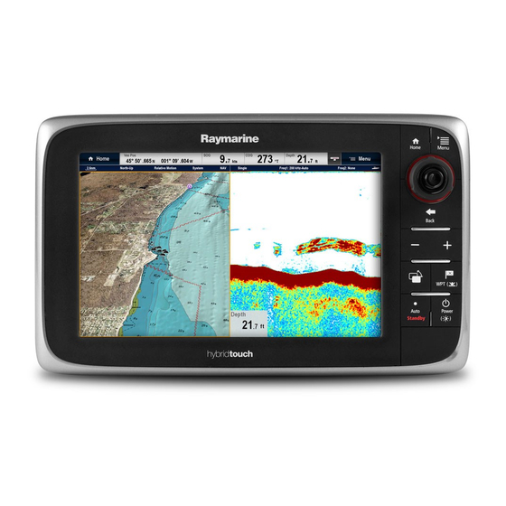
2.3 Handbook illustrations The illustrations and screenshots used in this handbook may differ slightly from your display model. The illustration of the multifunction display below is used throughout this manual and unless otherwise stated can apply to all variants of multifunction display (i.e. New a series, New c Series and New e Series). -
Page 17: Handbook Conventions
2.4 Handbook conventions The following conventions are used throughout this handbook when referring to: Type Example Convention Icons The term "select" is used in procedures involving icons to refer to the action of selecting an on-screen icon, either using touch or physical buttons: •... - Page 18 Waypoint (MOB) button / icon Depending on the multifunction display variant there will be either a Waypoint (MOB) button or an on-screen icon. WPT button • New c Series • New e Series WPT icons • New a Series Throughout this manual the term: Select WPT, refers to pressing the physical WPT button or pressing the on-screen WPT icon.
-
Page 19: Touch And Non-Touch Operations
2.5 Touch and non-touch operations This handbook applies to New a Series, New c Series and New e Series multifunction displays. All features and functions can be accessed using physical buttons (non-touch) on New c Series and New e Series displays or by using the touchscreen on New a Series and New e Series displays. - Page 20 New a Series / New c Series / New e Series...
-
Page 21: Chapter 3 Planning The Installation
Chapter 3: Planning the installation Chapter contents • 3.1 System integration on page 22 • 3.2 Installation checklist on page 26 • 3.3 System Limits on page 26 • 3.4 Multiple data sources (MDS) overview on page 27 • 3.5 Identifying your display variant on page 27 •... -
Page 22: System Integration
Suitable Devices Connections Remote control 1 per multifunction display. Raymarine RCU-3 Bluetooth For Raymarine wireless video streaming Smartphone / Tablet device 1 per multifunction display. • Chartplotter sync with Navionics and remote control apps: Marine app: Wi-Fi. • Video streaming and remote control: •... - Page 23 , or NMEA 0183. Raymarine • Raystar125 GPS. • Raystar125+ GPS (via optional SeaTalk to SeaTalk converter). • RS130 Instruments — Raymarine As determined by SeaTalk (via optional SeaTalk to SeaTalk SeaTalk, SeaTalk SeaTalk bus bandwidth converter): and power loading.
- Page 24 • Any 600 watt / 1Kw compatible transducer (via optional E66066 adaptor cable). ; OR: • Any Minn Kota transducer (via optional A62363 adaptor cable). Connection via external Raymarine Sonar Module: • Any sonar module-compatible transducer. VHF radio — Raymarine All Raymarine DSC VHF radios.
- Page 25 • Navionics Ready to Navigate. • Navionics Silver • Navionics Gold • Navionics Gold+ • Navionics Platinum • Navionics Platinum+ • Navionics Fish'N Chip • Navionics Hotmaps Refer to the Raymarine website (www.raymarine.com) for the latest list of supported chart cards. Planning the installation...
-
Page 26: Installation Checklist
3.2 Installation checklist 3.3 System Limits Installation includes the following activities: The following limits apply to the number of system components that can be connected in a Raymarine multifunction display Installation Task system. Plan your system. Component Maximum Obtain all required equipment and tools. -
Page 27: Multiple Data Sources (Mds) Overview
NOT compliant. It may be necessary to upgrade the software for these non-compliant products to make them compliant. Visit the Raymarine website (www.raymarine.com) to obtain the latest software for your products. If MDS-compliant software is not available and you... -
Page 28: Networking Constraints
General connected to a compatible sonar transducer. • Multifunction displays should be connected together using • If connecting an external sonar module unit to a a67, e7D, SeaTalk e97, e127, c97 or c127 then the internal sonar must be • Multifunction displays can also be connected via SeaTalk switched off. -
Page 29: Typical Systems
SeaTalk / RayNet SeaT alk / RayNet SeaT alk D12245-2 1. Raymarine Multifunction display. 2. Raymarine network switch. 3. Raymarine radar scanner. 4. SPX course computer. 5. SeaTalk Pilot controller. Note: A network switch is only required if multiple devices are connected using SeaTalk / RayNet. - Page 30 Example: Basic system with sonar variant display SMART SeaT alk / RayNet SeaT alk D12589-1 1. Multifunction display 2. Sonar transducer. 3. Radar scanner. 4. SPX course computer. 5. SeaTalk pilot controller. Example: Basic system with non-sonar variant display SMART SeaT alk / RayNet SeaT alk...
- Page 31 Example: Expanded system SeaT alk DeviceNet SeaT alk / RayNet SeaT alk / RayNet SeaT alk / RayNet SeaT alk / RayNet D12247-2 1. Radar scanner. 2. Weather sensor. 3. Sirius weather receiver. 4. Sonar module. 5. SeaTalk Pilot controller. 6.
-
Page 32: System Protocols
3.8 System protocols is generally used to connect a data receiver and a transmitter together, e.g. a compass sensor transmitting heading to a radar display. This information is passed in ‘sentences’, each of which Your Multifunction Display can connect to various instruments and displays to share information and so improve the has a three letter sentence identifier. -
Page 33: Data Master
3.9 Data master 3.10 New a Series parts supplied Any system containing more than one networked multifunction The following items are supplied with your multifunction display. display must have a designated data master. The data master is the display which serves as a primary source of data for all displays, it also handles all external sources of information. -
Page 34: E7 / E7D Parts Supplied
3.11 e7 / e7D Parts supplied 3.12 New c Series and New e Series parts supplied The parts shown below are supplied with the e7 / e7D multifunction display. The parts shown below are supplied with the New c Series and New e Series (Excluding e7 and e7D) multifunction displays. -
Page 35: Tools Required For Installation
3.13 Tools required for installation D12171-2 1. Power drill. 2. Jigsaw. 3. Pozidrive screwdriver. 4. Adhesive tape. 5. Spanner for surface mounting or bracket mounting fixings. 6. File. 7. Hole saw for flush mounting (For hole saw size refer to your product’s mounting template). - Page 36 New a Series / New c Series / New e Series...
-
Page 37: Chapter 4 Cables And Connections
Chapter 4: Cables and connections Chapter contents • 4.1 General cabling guidance on page 38 • 4.2 Connections overview on page 39 • 4.3 Power connection — New a Series on page 40 • 4.4 Power connection — New c Series and New e Series on page 41 •... -
Page 38: General Cabling Guidance
• Unless otherwise stated use only standard cables of the correct type, supplied by Raymarine. • Ensure that any non-Raymarine cables are of the correct quality and gauge. For example, longer power cable runs may require larger wire gauges to minimize voltage drop along the run. -
Page 39: Connections Overview
4.2 Connections overview Details of the connections available on Raymarine multifunction displays are shown below. a 65 a 67 e 7D e 95 / e 125 / e 165 e 97 / e 127 c95 / c125 c97 / c127... -
Page 40: Power Connection - New A Series
6. Black cable (negative). 5 A (if only connecting one device) Power distribution Raymarine recommends that all power connections are made Note: The suitable fuse rating for the thermal breaker is via a distribution panel. dependent on the number of devices you are connecting. If in •... -
Page 41: Power Connection - New C Series And New E Series
(approximately the distance from the battery to the display). To calculate the round trip length, double the figure stated here. Raymarine recommends that all power connections are made via a distribution panel. • All equipment must be powered from a breaker or switch, with Breakers, fuses and circuit protection appropriate circuit protection. - Page 42 Sharing a breaker Where more than 1 piece of equipment shares a breaker you must provide protection for the individual circuits. E.g. by connecting an in-line fuse for each power circuit. D11637-2 Positive (+) bar Negative (-) bar Circuit breaker Fuse Where possible, connect individual items of equipment to individual circuit breakers.
-
Page 43: Network Connections
• Ethernet IP cameras. Note: Your multifunction display includes the following network connectors: • e7, e7D, a65 and a67 = 1 x SeaTalk / RayNet connector. • New c Series and New e Series (excluding the e7 and e7D) = 2 x SeaTalk / RayNet connectors. - Page 44 There are 2 types of SeaTalk network cable — “patch” and Note: “network”. • Patch — for connecting the following devices to a Raymarine • New c Series and New e Series displays (excluding the e7 and e7D) can connect 2 SeaTalk / RayNet devices network switch: directly to the display.
- Page 45 D12254-1 1. Radar extension cable. 2. Radar power and data digital cable. 3. Raymarine network switch (or crossover coupler if connecting radar directly to display). 4. RayNet cable (or RayNet to SeaTalk cable if connecting via crossover coupler). Note: The extension cable connects to the radar scanner.
- Page 46 (including any extensions) is 25 m (82 ft). Note: You can also connect a sonar variant multifunction display to a Raymarine sonar module. This is useful in Radar power and data digital extension cables circumstances where you need a higher powered sonar These cables extend the power and data digital cables for a module for example.
- Page 47 Series multifunction displays. Note: New a Series does not support thermal cameras. The camera is connected via a Raymarine network switch. If you want to use the optional Joystick Control Unit (JCU) with the camera this must also be connected to the network switch.
- Page 48 Video cables Video cables are not supplied with the product. Please contact your dealer for suitable cables and adaptors. Raymarine recommends the use of a BNC terminated RG59 75ohm (or better) coaxial cable. IP Camera connections You can connect IP cameras to your multifunction display.
- Page 49 Fusion link connection Network connection You can connect a Fusion 700 series marine entertainment system to your multifunction display. Direct connection D12741-1 1. Multifunction display. 2. Fusion system. 3. RayNet to SeaTalk cable. 4. Fusion ethernet connector. Direct connection with networked multifunction displays D12740-1 1.
-
Page 50: Gps Connection
4.6 GPS connection 4.7 AIS connection Depending on display variant, your multifunction display may A compatible AIS can be connected using SeaTalk or NMEA include an internal GPS receiver. If required the multifunction 0183. display can also be connected to an external GPS receiver, Connection using SeaTalk using SeaTalk or NMEA 0183. -
Page 51: Fastheading Connection
The SeaTalk bus requires a 12 V power supply. Power may be provided from: • Raymarine equipment with a regulated 12 V power supply (for example, a SmartPilot SPX course computer); or: • Other suitable 12 V power supply. Note: SeaTalk... - Page 52 SeaTalk cabling components Description Part No Notes SeaTalk cabling components and their purposes. A06035 SeaTalk 3 m (9.8 ft) backbone Connection / Cable Notes SeaTalk 5 m (16.4 ft) A06036 Backbone cable (various lengths) The main cable carrying data. Spurs backbone from the backbone are used to connect SeaTalk...
-
Page 53: Seatalk Connection
4.10 SeaTalk connection 4.11 New a Series DSC VHF radio connection You can connect SeaTalk devices to your multifunction display using the optional SeaTalk to SeaTalk converter. The New a Series multifunction display requires an NMEA 0183 to SeaTalk converter and a powered SeaTalk backbone to enable connection to a DSC VHF radio. -
Page 54: Nmea 0183 Connection
4.12 NMEA 0183 connection Positive (+) / NMEA 0183 devices can be connected to New c Series and New Ite- Cable Input / negative e Series multifunction displays using the power and data cable. Device color Port output Note: New a Series does not support connection of NMEA NMEA Output Positive... -
Page 55: Nmea 2000 Connection
4.13 NMEA 2000 connection 4.14 Camera / Video connection The display can receive data from NMEA 2000 devices (e.g. A camera or a video device can be connected directly to New c data from compatible engines). The NMEA 2000 connection is Series and New e Series multifunction displays using the video made using SeaTalk and appropriate adaptor cables. -
Page 56: Camera / Video In-Out Connection
4.15 Camera / video in-out connection Connector type BNC (female) Output resolution 720p A camera / video device or external display can be connected to New e Series multifunction displays (excluding the e7 / e7D) using the dedicated video in/out connector. Video cables Note: New a Series and New c Series multifunction displays The following video cable is required for the video in / out... -
Page 57: Media Player Connection
4. Select New Bluetooth Connection. A message is displayed prompting you to put your media You can control audio wirelessly using a Raymarine RCU-3 remote control unit. player device into discovery mode. 5. Ensure Bluetooth is enabled on your external media player The Shortcut key on the RCU-3 must be set to Start/Stop audio device and ensure it is ready to be paired. -
Page 58: Bluetooth Remote Control Connection
6. Select Unpair / Forget this device. D12163-2 1. Multifunction display. 2. Bluetooth connection. 3. Raymarine Bluetooth remote control (for example, RCU-3). To use the remote control you must first: • Enable Bluetooth in the System Settings on the multifunction display. - Page 59 9. When prompted, press the arrow button on your remote that you wish to be configured as the UP button. The other arrow button will automatically be configured as the DOWN button. If the pairing was successful a “Pairing Success” message will be displayed.
-
Page 60: Remote Control Functions
4.18 Remote control functions Bu tto n s Arrow buttons Shortcut button Ra n g e P a ir S e le c t D12051-2 Button Application where function available: Default functions: Chart Radar Fishfinder Weather Homescreen Range / zoom. •... - Page 61 Reconnecting the RCU 1. When you pair the RCU-3 with a multifunction display a wireless connection is established. 2. When you power off the multifunction display it loses its connection with the RCU-3 after 10 minutes. 60 5 M inutes 3.
-
Page 62: Wifi Connections
You can use compatible tablet and smartphone devices as a wireless repeat display or remote control for your multifunction display. Raymarine apps allow you to stream and / or control, remotely what you see on your multifunction display to a compatible device, using a Wi-Fi connection. -
Page 63: Chapter 5 Location And Mounting
Chapter 5: Location and mounting Chapter contents • 5.1 Selecting a location on page 64 • 5.2 Mounting - New a Series on page 65 • 5.3 Mounting - New c Series and New e series on page 67 Location and mounting... -
Page 64: Selecting A Location
5.1 Selecting a location Warning: Potential ignition source This product is NOT approved for use in ( 7 . 8 5 0 0 hazardous/flammable atmospheres. Do NOT install . 7 i 7 i n ( 1 9 in a hazardous/flammable atmosphere (such as in 2 5 0 an engine room or near fuel tanks). -
Page 65: Mounting - New A Series
D12576-1 As display contrast, color and night mode performance are all a65 / a67 affected by the viewing angle, Raymarine recommends you temporarily power up the display when planning the installation, 60º to enable you to best judge which location gives the optimum 60º... - Page 66 D12585-2 1. Check the selected location for the unit. A clear, flat area with suitable clearance behind the panel is required. 2. Drill or knock out the 4 mounting holes on the unit D12578-2 1. Mark the location of the mounting bracket screw holes on the chosen mounting surface.
-
Page 67: Mounting - New C Series And New E Series
5.3 Mounting - New c Series and New display, ensuring that the clips along the bottom edge of the bezel latch into position. e series Viewing angle D12268-1 e95 / e97 / e125 / e127 / e7 / e7D e165 c95 / c97 c125 / c127 70º... - Page 68 1. Remove the front bezel. Refer to the separate instructions 3. Using a suitable hole saw (the size is indicated on the provided for that procedure. template), make a hole in each corner of the cut-out area. 4. Using a suitable saw, cut along the inside edge of the cut-out line.
- Page 69 • Attach the front bezel. display, ensuring that the clips along the bottom edge of the bezel latch into position. D12274-1 4. Ensure the bezel is correctly aligned with the display, as shown. 5. Apply firm but even pressure to the bezel along the: i.
- Page 70 New a Series / New c Series / New e Series...
-
Page 71: Chapter 6 Getting Started
Chapter 6: Getting started Chapter contents • 6.1 Display power on page 72 • 6.2 New a Series Controls on page 72 • 6.3 e7 / e7D Controls on page 73 • 6.4 c95 / c97 / c125 / c127 / e95 / e97 / e125 / e127 / e165 Controls on page 73 •... -
Page 72: Display Power
6.1 Display power 6.2 New a Series Controls Powering the display on 1. Press the POWER button. 2. Select Accept to acknowledge the disclaimer message. Powering the display on 1. Press the POWER button. 2. Press the OK button to accept the disclaimer message. Powering the display off D12577-1 1. -
Page 73: E7 / E7D Controls
6.3 e7 / e7D Controls 6.4 c95 / c97 / c125 / c127 / e95 / e97 / e125 / e127 / e165 Controls D12179-1 1. Touchscreen — you can touch the screen to operate many common functions, including all menu operations (HybridTouch multifunction displays only). - Page 74 List of cursor labels Label Feature Application Ruler line Chart AIS target Chart Course Over Ground Chart vector Center of radar Radar Floating EBL/VRM Radar Guard zone Radar Heading vector Chart MARPA MARPA target Radar Man Over Board Chart, Radar marker Vessel's position Chart...
-
Page 75: Hybridtouch Overview
In these situations, or moored. You may find it helpful to use the simulator mode Raymarine strongly recommends that you activate the touch lock (accessible from Homescreen > Set-up > System Settings) and use the physical keys to operate your multifunction display. -
Page 76: Homescreen Overview - New A Series
6.7 Homescreen overview — New a 6.8 Homescreen overview — New c Series Series / New e Series The homescreen provides a central point of access to your The homescreen provides a central point of access to your display's range of applications. display's range of applications. -
Page 77: System Checks
Course Over Ground (COG) data is available. The accuracy of the GPS receiver depends on the parameters Note: Raymarine recommends that you check the displayed detailed above, especially the azimuth and elevation angles vessel position in the chart application against your actual which are used in triangulation to calculate your position. - Page 78 • Sonar variant displays allow the direct connection of EITHER a Raymarine OR a Minn Kota sonar transducer. • All variants allow the connection of a Raymarine sonar transducer via a compatible external sonar module. • For all variants use the Transducer Set-Up menu in the fishfinder application to specify the sonar transducer you want to use.
- Page 79 4. Select Transducer. Panning and tilting, and the thermal image A list of transducers is displayed. On a New e Series multifunction display you can pan and tilt the 5. Select the transducer you want to use. thermal camera image using the touchscreen. Checking the sonar Move your finger up and down the screen to tilt the camera up or down.
-
Page 80: Enabling Autopilot Functions
6.10 Enabling autopilot functions 6.11 Enabling AIS functions With the homescreen displayed: Before proceeding ensure your AIS unit is connected to NMEA Port 1. 1. Select Set-up. With the homescreen displayed: 2. Select System Settings. 1. Select Set-Up. 3. Select Autopilot Control so that On is highlighted. 2. -
Page 81: Pages
6.12 Pages 5. Select the appropriate page layout (for example, “Splitscreen”). Pages are used to display applications. 6. Select the application(s) you want to display on the page, either by selecting the relevant menu item or dragging it over Pages are displayed and accessed on the homescreen. Each to the displayed page. -
Page 82: Applications
6.13 Applications 6.14 Splitscreen controls When viewing a page with more than 1 application displayed you Chart application — provides a 2D or 3D can switch applications from the splitscreen view to fullscreen graphical view of your charts to help you view. -
Page 83: Screen Overview
6.15 Screen overview Selecting the active window — e7 / e7D When viewing a splitscreen page you can select the active application and view it fullscreen on an e7 / e7D with the touch lock enabled by following the steps below. With a page featuring multiple applications displayed: 1. - Page 84 Screen item Description Back • Touchscreen — Select the on-screen Back icon to go back to the previous menu. • Non–touchscreen — Use the Back button to go back to the previous menu. Menu item • Touchscreen — Momentarily touching a menu item highlights and automatically selects the item.
- Page 85 Screen item Description Screen item Description Close — On Touchscreen displays you can select Status — provides status information for the connected this icon to close the menu(s). The close icon is not equipment. For example, the Pilot Control dialog available on non-touchscreen displays.
-
Page 86: Editing Information In Dialogs
6.16 Editing information in dialogs 6.17 Editing numerical settings With the dialog displayed: To edit numerical values in you can either use the Rotary Control, the on-screen numeric adjust control or on-screen 1. Select the field you want to edit. numeric keypad to increase or decrease the value. -
Page 87: Basic Touchscreen Operations
6.18 Basic touchscreen operations 6.19 Databar status symbols The status symbols on the databar confirm whether the Placing and moving the cursor using appropriate connections to your system have been made. touch The symbols show the status for the following: •... - Page 88 Symbol Description Symbol Description AIS unit is connected and switched on, but Power steering active. has active alarms. AIS unit is connected and switched on, but Wind Vane mode is active. the dangerous and lost alarm is disabled. Sonar status symbols The sonar status is indicated in the databar.
-
Page 89: Initial Set Up Procedures
6.20 Initial set up procedures Adjusting the display brightness — New a Series and New e Series Once your display has been installed and commissioned, Raymarine recommends that you perform an initial set up procedure. Startup wizard D12568-1 When you power-up the display for the first time or after a 1. -
Page 90: Data Master
The simulator mode is switched on / off in the System Setup Menu. Note: Raymarine recommends that you do NOT use the simulator mode whilst navigating. Note: The simulator will NOT display any real data, including any safety messages (such as those received from AIS units). -
Page 91: Chapter 7 Managing Display Data
Chapter 7: Managing display data Chapter contents • 7.1 Memory cards overview on page 92 • 7.2 Inserting a memory card or chart card on page 92 • 7.3 Removing a memory card or chart card on page 93 • 7.4 Saving user data and user settings on page 93 •... -
Page 92: Memory Cards Overview
2. Insert the card, as shown in the diagram below. For slot 1, Note: Raymarine recommends that you backup your data to the card contacts should be facing DOWN. For slot 2, the a memory card on a regular basis. -
Page 93: Removing A Memory Card Or Chart Card
Note: Raymarine recommends that you save your user data and user settings to a memory card on a regular basis. Note: Raymarine strongly recommends that you save settings to a separate memory card, and NOT to a chart card containing cartography. - Page 94 want to erase data from, if your display only has 1 card slot Application Setting then you will not be prompted. 4. Select SD1 for a memory card in the top card slot, or SD2 for TD set-up a memory card in the bottom card slot. Simulator 5.
- Page 95 Chart application — Cartography settings Data application Application Setting Application Setting Cartography Data overlay cell 1 on / off Data Datapages and content Data overlay cell 1 content Datapage order Data overlay cell 2 on / off Color theme Data overlay cell 2 content Dial color Chart object menu Number of engines...
-
Page 96: Screenshots
7.5 Screenshots 7.6 Resetting your system You can take a screenshot of what is currently displayed on the Your system may be reset to its factory default settings if screen. required. Screenshots are saved to an SD card in .bmp (bitmap) format. There are 2 types of reset operation, both of which affect the The saved image can be viewed from the multifunction display current display you are using, AND any networked displays. -
Page 97: Chapter 8 Document Viewer Application
Chapter 8: Document viewer application Chapter contents • 8.1 Document viewer overview on page 98 Document viewer application... -
Page 98: Document Viewer Overview
8.1 Document viewer overview • Fit to Width — Scales the open document to fit the width of the application window. Your multifunction display includes a pdf document viewer. • Close File — Closes the open document. The document viewer is available from the homescreen and is used to view and search pdf documents (such as product Opening the user manual handbooks). -
Page 99: Searching For Text
• The find tool bar is displayed. Browsing an open document • The first occurrence of the keyword is highlighted. On HybridTouch and non-touch displays you can browse pdf 5. Select Next to find the next occurrence of the keyword, or documents by following the steps below. - Page 100 New a Series / New c Series / New e Series...
-
Page 101: Chapter 9 Autopilot Control
Chapter 9: Autopilot control Chapter contents • 9.1 Autopilot control on page 102 • 9.2 Autopilot status symbols on page 103 • 9.3 Autopilot alarms on page 104 Autopilot control... -
Page 102: Autopilot Control
Distance to next waypoint. On multifunction displays which do not have a dedicated pilot Bearing to next waypoint. button (i.e. a65, a67, e7 and e7D) you can engage the autopilot from the Shortcuts menu. Next waypoint name. With the autopilot engaged: 1. -
Page 103: Autopilot Status Symbols
9.2 Autopilot status symbols 1. Select Menu > Navigate > Goto Cursor, Goto Waypoint, or Follow Route as appropriate. The autopilot status is indicated in the databar. The Pilot Control dialog is displayed. 2. Select Engage Pilot. Symbol Description A confirmation pop-up message is displayed. Autopilot is in Standby mode. -
Page 104: Autopilot Alarms
9.3 Autopilot alarms The autopilot function provides alarms to alert you to situations that require action. Your multifunction display shows autopilot alarms, regardless of whether there is active navigation on the system. If autopilot control is enabled, and an alarm is raised by the autopilot, the multifunction display provides an audible alarm sound (providing that the alarm has not already been silenced). -
Page 105: Chapter 10 Alarms And Man Over Board Functions
Chapter 10: Alarms and Man over board functions Chapter contents • 10.1 Using Man Overboard (MOB) functions on page 106 • 10.2 Alarms on page 107 Alarms and Man over board functions... -
Page 106: Using Man Overboard (Mob) Functions
The MOB alarm is cancelled and normal operation is • An MOB alarm dialog box is displayed. resumed. • The system sends MOB alarms to other Raymarine equipment. • The active chart application is changed to a low-detail 2D view, with an initial range of 15 m (50 ft). Motion mode is set to Auto Range. -
Page 107: Alarms
10.2 Alarms Alarms alert you to a situation or hazard requiring your attention. You can set up alarms to alert you to certain conditions, such as collision warnings and temperature limits. Alarms are raised by system functions, and also external equipment connected to your multifunction display. - Page 108 Alarms menu Menu item Description Options MOB Data Type Determines whether Position or Dead Reckoning (DR) data is • Dead Reckoning displayed. Assuming that your vessel and the MOB are subject to the • Position (default) same tide and wind effects, the Dead Reckoning setting normally gives a more accurate course.
- Page 109 Menu item Description Options • Deep Fish Limit — Specifies the upper value for the Fish Alarm • 2 ft (or equivalent units) to the maximum of the Depth Limit. transducer range Deep Fish Limit • 2 ft (or equivalent units) to the maximum of the transducer range Fuel Manager In the fuel manager alarm options you can switch the low fuel warning...
- Page 110 New a Series / New c Series / New e Series...
-
Page 111: Chapter 11 Dsc Vhf Radio Integration
Chapter 11: DSC VHF radio integration Chapter contents • 11.1 Using a DSC VHF radio with your display on page 112 • 11.2 Enabling DSC VHF radio integration on page 112 DSC VHF radio integration... -
Page 112: Using A Dsc Vhf Radio With Your Display
11.1 Using a DSC VHF radio with your 11.2 Enabling DSC VHF radio display integration You can connect your DSC VHF radio to your multifunction With the homescreen displayed: display and show distress message information and GPS 1. Select Set-up. position data for other vessels. -
Page 113: Chapter 12 Fuel Manager
Chapter 12: Fuel manager Chapter contents • 12.1 Fuel manager overview on page 114 Fuel manager... -
Page 114: Fuel Manager Overview
12.1 Fuel manager overview Note: Fuel manager estimates the amount of fuel onboard, based on The fuel manager provides an estimate of fuel remaining, and the user logging each time you fill up, the total fuel capacity, the distance and time which can be travelled before the tanks and how much fuel is burned by the engine(s). - Page 115 Setting the low fuel alarm Note: Using the fuel manager also allows you to set a low fuel alarm The fuel range ring is an estimated range that can be reached which, if activated, is sounded when your vessel’s remaining at the current rate of fuel consumption, of the fuel onboard fuel falls to a specified value.
- Page 116 New a Series / New c Series / New e Series...
-
Page 117: Chapter 13 Ais Function
Chapter 13: AIS function Chapter contents • 13.1 AIS overview on page 118 • 13.2 AIS prerequisites on page 119 • 13.3 AIS context menu on page 119 • 13.4 Enabling AIS on page 120 • 13.5 Displaying AIS vectors on page 120 •... -
Page 118: Ais Overview
13.1 AIS overview AIS Simulator Mode Raymarine recommends that you use the simulator function to The AIS feature enables you to receive information broadcast by familiarize yourself with the AIS features. When the simulator other vessels, and to add these vessels as targets in the chart function is enabled (homescreen >... -
Page 119: Ais Prerequisites
13.2 AIS prerequisites 13.3 AIS context menu You must have suitable AIS hardware connected to your The AIS function includes a context menu which provides AIS multifunction display to make use of the AIS functionality. target information and menu items. In order to run AIS, you will need: •... -
Page 120: Enabling Ais
13.4 Enabling AIS 13.5 Displaying AIS vectors You must have the correct data available before AIS vectors Enabling AIS in the chart application can be displayed. To enable AIS overlay in the chart application the chart view A target is defined as active when it has the following data must be set to 2D Menu >... -
Page 121: Ais Status Symbols
13.6 AIS status symbols 13.7 AIS silent mode AIS status is indicated by a symbol in the databar. AIS silent mode enables you to disable AIS transmissions AIS silent mode enables you to disable the transmitting functions Symbol Description of your AIS equipment. This is useful when you do not want to AIS unit is switched on and operating. -
Page 122: Ais Target Symbols
13.8 AIS target symbols 13.9 Displaying detailed AIS target information Your multifunction display shows a range of symbols to represent the different types of AIS target. From the chart or radar application: Target type Description Symbol 1. Select an AIS target. The AIS target context menu is displayed. -
Page 123: Viewing All Ais Targets
13.10 Viewing all AIS targets 13.11 Using AIS to avoid collisions You can use the AIS safe zone and safety message functions to From the chart application go to Menu > AIS Options help you avoid collisions with other vessels and objects. From the radar application go to Menu >... -
Page 124: Ais Options
13.12 AIS options Enabling and disabling AIS safety messages in the radar application The AIS options are accessible in the chart application by From in the radar application: selecting Menu > AIS Options > MARPA & AIS Options or the radar application by selecting Menu >... -
Page 125: Ais Alarms
13.13 AIS alarms 13.14 Buddy tracking The Buddy Tracking feature enables you to add AIS-equipped The AIS functions generate a number of alarms to alert you to friends and regular contacts to a “Buddy List” on your dangerous or lost targets. multifunction display. - Page 126 i. Select Yes to enter a name for the buddy vessel ii. Select No to save the vessel to your buddy list without entering a name for the buddy vessel. The vessel will now be added to your buddy directory. Adding a vessel to your buddy list from AIS target list 1.
-
Page 127: Chapter 14 Waypoints, Routes And Tracks
Chapter 14: Waypoints, Routes and Tracks Chapter contents • 14.1 Waypoints on page 128 • 14.2 Routes on page 133 • 14.3 Tracks on page 136 • 14.4 Waypoints, routes and tracks storage capacity on page 138 Waypoints, Routes and Tracks... -
Page 128: Waypoints
14.1 Waypoints Showing and hiding waypoint groups / symbols From the chart or radar application: A waypoint is a position marked on the screen to indicate a site 1. Select WPT. or a place to navigate to. 2. Select Display Wpts on: Chart, or Display Wpts on: Radar As well as acting as position markers, waypoints are also the depending on the application you have open. - Page 129 • Stop Goto From the chart, radar or fishfinder application: 1. Select and hold the required location on screen. • Restart XTE The context menu is displayed. • Advance Waypoint 2. Select Place Waypoint. • Measure • Build Route Placing a waypoint •...
- Page 130 Navigating to a waypoint on the screen In the event that you steer off-track, you can go straight to your target by resetting XTE. Resetting Cross Track Error (XTE) While following a route in the chart application: 1. Select the route. The route context menu is displayed.
- Page 131 4. Use the on-screen keyboard to make the changes, then Symbol Type Symbol Type select the on-screen keyboard's SAVE button. Trawler Tree Editing a waypoint using the context menu Triangle Wreck 1. Select the waypoint. The waypoint context menu is displayed. 2.
- Page 132 Waypoint groups 2. Select the group you want all new waypoints to be placed in by default. In order to make your waypoints easier to manage, you can 3. Select Default Symbol. organize them into groups of your choice. When fishing, for example, you may only wish to see the waypoints that indicate 4.
-
Page 133: Routes
14.2 Routes 1. Select and hold a location on screen. The chart context menu is displayed. A route is a series of waypoints typically used to assist with 2. Select Build Route. passage planning and navigation. The build route menu is displayed. A route is displayed on screen as a series of waypoints linked 3. - Page 134 1. Use the Range In and Range Out buttons to range in and Route context menu out of the chart. Placing the cursor over a route in the chart application displays a context menu showing the leg of the route highlighted by the cursor and menu items.
- Page 135 • From a selected waypoint or any leg within a route. You can also follow any route in reverse order. Following a stored route From the chart application: 1. Select Menu. 2. Select Navigate. 3. Select Follow Route. The Route list is displayed. 4.
-
Page 136: Tracks
14.3 Tracks Moving a waypoint within a route From the chart application: A track is an on-screen trail that shows the passage you have 1. Position the cursor over the waypoint you want to move. taken. This trail is made up of a series of track points which are created automatically. - Page 137 • Time— The track points are placed at regular intervals of • Erase a track. time. • Create a route from a track. • Distance— The track points are placed at regular intervals • Show or hide a track on the chart (only available from the of distance.
-
Page 138: Waypoints, Routes And Tracks Storage Capacity
14.4 Waypoints, routes and tracks storage capacity The display can store the following quantities of waypoints, routes and tracks Way- • 3000 Waypoints points • 100 waypoint groups Routes • 150 routes, each consisting of up to 50 waypoints. Tracks •... -
Page 139: Chapter 15 Chart Application
Chapter 15: Chart application Chapter contents • 15.1 Chart application overview on page 140 • 15.2 Chart ranging and panning on page 141 • 15.3 Vessel position and orientation on page 142 • 15.4 Chart views on page 144 • 15.5 Chart context menu on page 145 •... -
Page 140: Chart Application Overview
15.1 Chart application overview • If you have a Raymarine GPS receiver using NMEA0183, or a third-party GPS receiver, you must correlate it separately. The chart application provides an electronic chart with passage It may be possible to use your multifunction display to correlate planning and navigation features. -
Page 141: Chart Ranging And Panning
Preferences > • Enable Wi-Fi on your tablet / smartphone. Range Controls • Select the Raymarine Wi-Fi connection from the list of available Wi-Fi networks on your tablet / smartphone. Panning the chart You can pan the chart area on a touchscreen multifunction display by following the steps below. -
Page 142: Vessel Position And Orientation
15.3 Vessel position and orientation Head-Up Vessel position on the chart display Your current position is represented on screen by the vessel symbol. The symbol used for your vessel will vary depending on the vessel type selected during initial set up of your multifunction display. - Page 143 Note: In the 3D chart view, only Relative Motion mode is Note: It is not possible to select True Motion when the available. orientation is set to Head Up. The current motion mode applies to the active instance of the Auto Range chart application.
-
Page 144: Chart Views
15.4 Chart views 3D chart view The 3D view can display a range of information to help you Switching between 2D/3D chart view navigate. You can switch between 2D and 3D views. From the chart application: 1. Select Menu. 2. Select Presentation . 000°T 3. -
Page 145: Chart Context Menu
15.5 Chart context menu ii. New a series or New e Series — Swipe your finger up or down across the screen to adjust the pitch. Placing the cursor over an area in the chart application displays D11755-1 a context menu showing the cursors positional data and menu items. -
Page 146: My Data Options
15.6 My Data options 15.7 Navigation options The chart provides features to help you manage your data and The chart application provides features to help navigate to a help plan your navigation to a chosen location. chosen location. The options are found in the My Data menu: Menu > My Data. The navigation options are found in the Navigate menu: Menu >... -
Page 147: Measuring Distances And Bearings
15.8 Measuring distances and 15.9 Chart vectors bearings Chart vectors display indicators for heading, COG, wind direction and tide direction. You can use the databar and context menu information you can use the measure function to measure distances in the chart A range of vector graphics can be displayed in the chart application. -
Page 148: Current Information
15.10 Current information 7. To set the animation date to 24 hours ahead of the current date select Next Day. Animated current information Displaying details of currents The electronic charts may allow animation of the current information current stations. From the chart application: 1. -
Page 149: Tide Information
15.11 Tide information Tide graphs Tide graphs provide a graphical view of tidal activity. Animated tide information The electronic charts may allow animation of the tide information tide stations. Animated tide information is available in the chart application wherever a diamond-shaped symbol with a "T" is displayed: This symbol identifies tide stations and the availability of tide information for the location. -
Page 150: Chart Object Information
15.12 Chart object information 5. Select SEARCH. The search results are displayed. You can display additional information on the chart for 6. Select an entry in the list to display more information. cartographic objects, ports, and marinas. You can also search for the nearest instance of a particular chart Displaying pilot book information object and search for ports by name. -
Page 151: Chart Presentation
15.13 Chart presentation • Radar — Overlay radar onto the chart (2D view only). • NOWRad — Provides the NOWRad weather radar overlay, The chart has a number of presentation options which affect the without the need to open a separate weather application level of detail, types of objects and aspects of its operation. - Page 152 Radar overlay NOWRad weather overlay You can combine the chart with the radar and MARPA functions With a suitable weather receiver connected to your multifunction to provide target tracking or to help you distinguish between display, you can overlay NOWRad weather information on the chart display.
- Page 153 Safe Zone Ring Note: The chart application can display and configure a MARPA / AIS The fuel range ring is an estimated range that can be reached safe zone ring. at the current rate of fuel consumption, of the fuel onboard and based on a number of external factors which could either extend or shorten the projected range.
- Page 154 3. Select Layers. 4. Select 3D Display Options. 5. Select Transducer Cone so that On is highlighted. Selecting Transducer cone will switch the function on and off. Enabling depth scale To enable a depth indicator at your vessels location follow the steps below: In 3D view: 1.
-
Page 155: Chart Set-Up Menu Options
15.14 Chart set-up menu options The following table describes the various options in the Chart Set-up Menu for your multifunction display. Menu item Description Options Context Menu (Touchscreen displays only) Determines how the context menu is • Touch — touching a chart object opens the accessed using touch context menu. - Page 156 Cartography set-up menu options The following table describes the various options in the Cartography Set-up Menu for your multifunction display. Menu item Description Options Chart Display Determines the level of detail shown on the chart. • Simple • Detailed (default) •...
- Page 157 Menu item Description Options Nav. Marks Determines whether navigation marks are displayed on the chart: • Off • On (default) • Off — navigation marks are NOT displayed. • On — navigation marks are displayed. Nav. Marks Symbols Determines which set of navigation mark symbols is used — •...
- Page 158 New a Series / New c Series / New e Series...
-
Page 159: Chapter 16 Radar Application
Chapter 16: Radar application Chapter contents • 16.1 Radar overview on page 160 • 16.2 Radar scan speed on page 161 • 16.3 Radar scanner status symbols on page 161 • 16.4 Radar range and image quality on page 162 •... -
Page 160: Radar Overview
Note: Features not listed are supported by all types of Radar Features Raymarine Non-HD Digital, HD and SuperHD radars. Depending on the type of Raymarine radar you have different features will be available to you, the table below shows which features and settings are supported by radar type:... -
Page 161: Radar Scan Speed
Selecting radar scan speed time periods. When you return to transmit The speed option requires a 48 RPM compatible Raymarine HD mode, the magnetron does not need to radome or Raymarine SuperHD open array radar scanner. -
Page 162: Radar Range And Image Quality
16.4 Radar range and image quality 2. Select Power up Radar to turn the radar on, or Power down Radar to turn the radar off. 3. Select Radar: Tx to start the radar transmitting, or Radar: Maximum radar range Stdby to stop the radar transmitting. The usable range of the radar is limited by factors such as the height of the scanner, and height of the target. - Page 163 Blind Sectors Obstructions such as funnels and masts near the radar antenna may obstruct the radar beam and cause radar shadows or ‘blind sectors’. If the obstruction is relatively narrow, there will be a reduction of the beam intensity, though not necessarily a complete cut-off.
-
Page 164: Radar Display Overview
16.5 Radar display overview clutter off With your radar scanner connected and the radar in transmit mode, the radar picture provides a map-like representation of the area in which the radar is operating. clutter in auto D12207-2 Item Description Range Interference On-screen controls (Touchscreen multifunction displays only.) -
Page 165: Dual Range Radar Operation
16.6 Dual range radar operation is dependent on many factors and may not necessarily be proportional to its physical size. Nearby objects may appear to The Dual Range radar function enables you to view 2 ranges at be the same size as distant larger objects. the same time in separate windows. -
Page 166: Radar Mode And Orientation
16.7 Radar mode and orientation Scanner Dual Range mode Operating mode 4 Kw SuperHD Open Long SuperHD Radar orientation modes Array The radar can operate in a number of orientation modes to suit Short different types of navigation. 12 Kw SuperHD Open Long SuperHD The orientation of the radar refers to the relationship between... - Page 167 Course-Up The default motion mode is “Relative”, with zero offset. True Motion (TM) When the motion mode is set to True, fixed radar targets maintain a constant position and moving vessels (including your vessel) travel in true perspective to each other and to fixed landmasses on the screen.
-
Page 168: Radar Tuning: On-Screen Gain Controls
16.8 Radar tuning: On-screen gain controls Touchscreen multifunction displays provide on-screen access to controls for Gain, Rain and Sea clutter. Gain control Rain control Sea control Note: non-touchscreen controls are accessed by the menu options: Menu > Rain and Menu > Adjust Gain. Enabling and disabling on-screen gain controls You can enable and disable the on-screen gain controls by... -
Page 169: Radar Adjustments: Hd And Superhd Scanners
Adjusting radar preset gain 1. Select Menu. Raymarine strongly recommends the use of the preset gain 2. Select Adjust Gain <Mode>, where <Mode> shall be the modes to achieve optimum results. However if required manual Auto Gain mode already selected. - Page 170 6. Select the Auto box so that a tick is placed in the box for automatic gain control. Adjusting radar anti sea clutter From the radar application, with the required Auto Gain Mode selected: 1. Select Menu. 2. Select Adjust Gain <Mode>, where <Mode> shall be the Auto Gain mode already selected.
-
Page 171: Radar Adjustments: Non-Hd Digital Radomes
Raymarine • Coastal — accounts for the slightly higher strongly recommends the use of these presets levels of sea clutter you might encounter to achieve optimum results. -
Page 172: Radar Presentation Menu Options
16.11 Radar presentation menu options Function Description Options Dual Range This menu item allows you to turn Dual range mode On and Off. • On • Off • 1 Dual Range Channel This menu item allows you to choose long or short channel for dual range. •... - Page 173 Function Description Options Data Overlay Set-up This menu item contains a sub-menu which enables you to turn on and select Data Cell 1 & 2 information to display in data cells located on the bottom left of the radar • On application (Data cells will be displayed in all radar windows).
- Page 174 True motion mode example D12745-1 Ships heading marker. Target travelling at between 0 kt to 1 kt (Minimal to no wake). Target moving in opposite direction to vessel (Wake appears in opposite direction to your vessel’s heading). Target moving in same direction as vessel (Wake appears towards your vessel’s heading).
-
Page 175: Using Radar To Measure Distances, Ranges, And Bearings
16.12 Using radar to measure Measuring using VRM/EBL distances, ranges, and bearings Variable Range Markers (VRM) A Variable Range Marker (VRM) is a circle centred on your When you are using the radar application, you can measure vessel’s position and fixed with respect to the heading mode. distances, ranges and bearings in a variety of ways. - Page 176 VRM/EBL context menu 1. Position the cursor over the VRM/EBL. The VRM/EBL function includes a context menu which provides 2. Press the Ok button. positional data and menu items. The radar context menu is displayed. 3. Use the Rotary Control to select Float Center. 4.
-
Page 177: Using Radar To Track Targets And Avoid Collisions
15. Select Ok to close the numeric adjust control. MARPA will perform. For the best heading data, a Raymarine 16. Select Bearing: . SMART heading sensor or a gyro-stabilized autopilot is required. - Page 178 There are conditions where acquiring a target may become Accessing the context menu difficult. These same conditions may be a factor in successfully You can access the context menu by following the steps below. tracking a target. Some of the conditions are: 1.
- Page 179 4. Select View MARPA List. 5. Select the relevant target. 5. Select the relevant MARPA target from the list. 6. Select View Full Target Data. 6. Select Cancel Target or Cancel All Targets. Vessel vectors (CPA graphics) overview CPA graphics show vectors for your vessel and a selected target. A vector is a line on-screen showing the predicted courses of your vessel and the selected target if you both remain on your present course.
-
Page 180: Scanner Set-Up Menu Options
Tune Adjust This menu item allows you to fine tune the radar scanner's receiver for maximum returns on the display. Raymarine recommends that this function is • Auto set to Auto. If you set this function to Manual and adjust the setting shortly after powering up the radar scanner, you should adjust it again approximately •... -
Page 181: Resetting The Radar
16.15 Resetting the radar To reset radar settings to defaults follow the steps below: From in the radar application: 1. Select Menu. 2. Select Scanner Set-up. 3. Select Advanced Set-up. 4. Select Reset Advanced. A confirmation pop up message is displayed. 5. - Page 182 New a Series / New c Series / New e Series...
-
Page 183: Chapter 17 Fishfinder Application
Chapter 17: Fishfinder application Chapter contents • 17.1 How the fishfinder works on page 184 • 17.2 Raymarine sonar modules on page 184 • 17.3 Traditional sonar technology on page 185 • 17.4 Broadband CHIRP sonar technology on page 185 •... -
Page 184: How The Fishfinder Works
17.1 How the fishfinder works 17.2 Raymarine sonar modules The fishfinder application uses a sonar module and a suitable The table below lists Raymarine’s sonar modules and whether sonar transducer. The sonar module interprets signals from the CHIRP technology is used. -
Page 185: Traditional Sonar Technology
17.3 Traditional sonar technology 17.4 Broadband CHIRP sonar technology Traditional sounders use a single carrier frequency or carrier wave for the sonar ping. These sounders work by measuring Broadband sonars use a swept frequency 'CHIRP' signal which the time it takes the ping echo to return to the transducer to can distinguish between multiple close targets, this enables determine target depth. -
Page 186: Fishfinder Introduction
17.5 Fishfinder introduction • Icon greyed-out - no fishfinder transducer is connected. Warning: Sonar operation Fishfinder context menu • NEVER operate the sonar with the vessel out of The fishfinder application includes a context menu which the water. provides fishfinder information and shortcuts to menu items. •... -
Page 187: Transducer Bandwidth
17.6 Transducer bandwidth 17.7 The sonar image The fishfinder application displays the fishfinder frequency, Interpreting the seabed using sonar center frequency or CHIRP mode depending on the connected sonar module and transducer. It is important to understand how to correctly interpret the seabed structure represented in the fishfinder display. -
Page 188: Fishfinder Presets
17.8 Fishfinder presets The fishfinder provides you with four preset configurations available from the fishfinder menu. These enable you to quickly select appropriate settings tailored for various situations. Each preset has been configured to provide the best operating parameters for the fishfinder. However, it is possible to manually adjust the presets if necessary. -
Page 189: Dual / Single Frequency Fishfinder
17.9 Dual / Single frequency fishfinder 17.10 Non-CHIRP (traditional) sonar module frequency controls Dual frequency operation allows the sonar to operate and display 2 frequencies simultaneously. If the preset mode that The frequency of the sonar determines the width of the sonar you are using has two frequencies configured, you can view beam, the depth to which the signals will penetrate and the either one or both of those frequencies in separate windows. -
Page 190: Chirp Sonar Module Frequency Controls
17.11 CHIRP sonar module frequency The graph above depicts an example of the fine tuning (from —50% to +50%) available when the frequency is set to 200 kHz. controls Tuning the fishfinder frequency (non-CHIRP sonar module) The frequency of the sonar determines the width of the sonar When connected to a non-CHIRP sonar module you can beam, the depth to which the signals will penetrate and the manually tune the fishfinder frequency. - Page 191 Frequency adjustment (CHIRP sonar module in non-CHIRP mode) When using a CHIRP sonar module in CHIRP mode (Low Chirp, Med Chirp or High Chirp) the frequency cannot be adjusted. When using a CHIRP sonar module in a non-Chirp mode (e.g. 50 kHz or 160 kHz) the frequency at which the transducer is transmitting can be adjusted.
-
Page 192: Fishfinder Display Modes
17.12 Fishfinder display modes 7. Select Back or use the Ok button to confirm the setting. Adjusting the position of the fishfinder zoomed area Selecting a fishfinder display mode When the zoom function is selected, the system automatically From the fishfinder application: selects the zoom position so that the bottom details are always in the lower half of the display. -
Page 193: Fishfinder Range
17.13 Fishfinder range Bottom Lock The Bottom Lock function applies a filter to flatten the image of The Range and Range Shift functions enable you to change the the seabed and make any objects on or just above it easier to range of depth displayed by the fishfinder. -
Page 194: Fishfinder Sensitivity Settings
Selecting the frequency for gain adjustments 5. Exit the menu. When connected to a Raymarine CHIRP sonar module, the gain 6. Use the Range control to change the range for the selected for frequency 1 and frequency 2 can be changed independently frequency. - Page 195 2. Select the Auto box to switch between Auto and Manual gain. 3. With Auto deselected, select and hold the Slider and move When connected to a Raymarine CHIRP sonar module 3 preset Left to decrease value or Right to increase value.
- Page 196 When in manual mode the slider bar control is shown: • Auto Selecting the frequency for TVG adjustments When connected to a Raymarine CHIRP sonar module, the TVG Non-CHIRP controls for frequency 1 and frequency 2 can be changed independently TVG auto modes are not available when connected to a or both at the same time.
-
Page 197: Fishfinder Presentation Options
• Sunburst Setting the frequency for power mode • Greyscale When connected to a Raymarine CHIRP sonar module, the power mode for frequency 1 and frequency 2 can be changed • Inverse Greyscale independently or both at the same time. If connected to a •... -
Page 198: Depth And Distance With The Fishfinder
17.16 Depth and distance with the Menu Item Description Options fishfinder bottom left corner of • Off the screen: The fishfinder display provides a number of features to help you Select Data Category • Data Cell 1 determine depths and distances. These features are illustrated Allows selection of a and described in more detail below: data type by category. -
Page 199: Fishfinder Scrolling
17.17 Fishfinder scrolling The fishfinder image scrolls from right to left. You can pause the scrolling or adjust the scroll speed, to ease placing of waypoints or VRMs on-screen. Scroll speed You can adjust the speed at which the fishfinder image scrolls. A faster speed provides more detail which may be useful when you are looking for fish. -
Page 200: Fishfinder Waypoints
17.18 Fishfinder waypoints 17.19 Fishfinder alarms The display can be configured to provide a number of fishfinder Placing a waypoint on the fishfinder display enables you to mark alarms. a position so that you can return to it later. The following fishfinder alarms can be set when a sonar module When a waypoint is placed, its details are added to the waypoint is detected, or when the simulator is on: list and a vertical line labelled WPT is displayed on-screen. -
Page 201: Sounder Set-Up Menu Options
17.20 Sounder set–up menu options This section describes the settings you can change using the sounder set up menu: (Menu > Set-up > Sounder Set-up). The set up menu contains settings that are likely to be changed infrequently. Menu Item Description Options Internal Sounder... -
Page 202: Transducer Set-Up Menu Options
17.21 Transducer set-up menu options The Transducer Set-up menu should be used when setting up your multifunction display for the first time or when installing a depth transducer. Menu Item Description Options Transducer Select the appropriate transducer type from those displayed. Options available are dependant on the sonar Some transducer may be detected by the system module connected. -
Page 203: Resetting The Sonar
The reset function restores the unit to its factory default values. Note: Performing a factory reset will clear speed and temperature calibration settings and the depth offset. 1. Using a compatible Raymarine multifunction display go to the Fishfinder application page. 2. Select Menu from the side menu. - Page 204 New a Series / New c Series / New e Series...
-
Page 205: Chapter 18 Data Application
Chapter 18: Data application Chapter contents • 18.1 Data application overview on page 206 • 18.2 Pre-configured datapages on page 206 • 18.3 Customizing the data application on page 208 Data application... -
Page 206: Data Application Overview
Default page data items e95 / e97 / c95 / c97 / e125 / Datapage a65 / a67 / e7 / e7D e127 / c125 / c127 / e165 Navigation • Rolling road • COG & SOG panel •... - Page 207 / e97 / c95 / c97 / e125 / e95 / e97 / c95 / c97 / e125 / Datapage a65 / a67 / e7 / e7D e127 / c125 / c127 / e165 Datapage a65 / a67 / e7 / e7D...
-
Page 208: Customizing The Data Application
18.3 Customizing the data application You can customize the data application to show the system and instrument data that you require. In addition to displaying the default, pre-configured datapages in the data application, you can also: • Change the order datapages appear. •... - Page 209 Customizing datapage content From the data application: 6. Select the data item you want to display. 1. Select Menu. Once selected a tick will be placed next to the data item in the menu and the cell on screen will display the new data item 2.
- Page 210 Data Category Description Data Item Digital Dial Graphical Fuel Types of data related Fuel Level 1 (vol) to the fuel system. For example, fuel levels. Fuel Level 2 (vol) Note: The options displayed are Fuel Level 3 (vol) dependant on the number of engines Fuel Level 1 (%) set in the data...
- Page 211 Data Category Description Data Item Digital Dial Graphical Navigation Types of data related Cursor Position (Only to navigation. For available in the Databar example, bearing to and data overlay.) waypoint. Cursor info Cross Track Error Rolling Road (Only available in the Data application.) Compass Target Position...
- Page 212 7. Select the data item you want to display. 4 Engines Once selected a tick will be placed next to the data item in the menu and the cell on screen will display the selected data item. 8. Repeat steps 3 to 6 for all the data items you want to change. 9.
- Page 213 Datapage and dial colors Datapage color theme and dial colors can be switched between light and dark. Color Theme Dial Color Example Light Light Light Dark Dark Dark Dark Light Resetting all datapages You can reset the datapages in the data application to the factory defaults.
- Page 214 New a Series / New c Series / New e Series...
-
Page 215: Chapter 19 Thermal Camera Application - Pan And Tilt Cameras
Chapter 19: Thermal camera application — Pan and tilt cameras Chapter contents • 19.1 Thermal camera application overview on page 216 • 19.2 Thermal camera image on page 216 • 19.3 Controls overview on page 217 • 19.4 Camera control on page 218 •... -
Page 216: Thermal Camera Application Overview
19.1 Thermal camera application 19.2 Thermal camera image overview The thermal camera provides a video image which is shown on your display. The thermal camera application enables you to control a connected thermal camera and display its image on your multifunction display. -
Page 217: Controls Overview
Icon Description Rear-view mode — image is flipped horizontally. The thermal camera application is available on compatible Raymarine multifunction displays and systems. It includes controls for the thermal camera. Zoom setting: 2x zoom. Rotary control Zoom image in / out. -
Page 218: Camera Control
19.4 Camera control Panning and tilting, and the thermal image On a New e Series multifunction display you can pan and tilt the Power up and standby thermal camera image using the touchscreen. When the breaker connecting power to the camera is switched Move your finger up and down the screen to tilt the camera on, the camera will run a boot up sequence lasting for about 1 up or down. - Page 219 • Medium • Fast 5. Select the required option. Thermal camera stabilization The Raymarine T470SC and T473SC thermal cameras includes a mechanical stabilization feature. The mechanical stabilization feature improves image stability by compensating for vessel motion and keeping the camera aimed at the point of interest.
-
Page 220: Image Adjustments
19.5 Image adjustments Thermal camera reverse video You can reverse the polarity of the video image to change the Adjusting the thermal camera image appearance of objects on-screen. The reverse video option (video polarity) switches the thermal With the thermal camera application displayed: image from white-hot (or red-hot if the color mode setting is 1. - Page 221 3. Use the Image Type menu item to switch between IR and 4. Adjust the value to the required setting. Visible Light views, as appropriate. This value will adjust the camera’s offset position to port or starboard. Thermal camera rear view mode Enabling / disabling automatic slew to cue The rear view mode flips the video image horizontally, providing From the thermal camera application:...
-
Page 222: Pan And Tilt Camera - New Camera Interface
19.6 Pan and tilt camera — new camera interface The thermal camera application menu options for a pan and tilt thermal camera with the new camera interface are shown below. Brings the thermal camera out of standby mode. (only available when camera is in standby.) Activate Camera Pause Image •... - Page 223 Camera Set-up menu Set Home Position Sets the camera’s current position as the Camera Home position. Slew Settings Provides automatic slew options and camera • Auto Slew to MOB alignment settings. • Auto Slew to dangerous AIS target • Auto Slew to dangerous MARPA target •...
- Page 224 Note: The thermal camera menu options available are dependant on the software version of your multifunction display and thermal camera. If options are different than listed above please refer to the manual that accompanied your thermal camera and / or the installation and operations handbook which accompanied your multifunction display. New a Series / New c Series / New e Series...
-
Page 225: High Power And High Torque Modes
19.7 High power and high torque modes Single Camera State Camera setting Dual payload payload Standby • High Power Mode 22 W 17.4 W • High Torque Mode Standby • High Power Mode 7.4 W • High Torque Mode • High Power Mode 13 W 13 W Standby... -
Page 226: Pan And Tilt Camera - Old Camera Interface
If options are different than listed above please refer to the manual that accompanied your thermal camera and / or the installation and operations handbook which accompanied your multifunction display. Note: It may be possible to update your camera to the new camera interface. Please contact your Raymarine dealer for details. OSD menu options... - Page 227 Surveillance mode menu System Setup Settings to optimize operation for this particular system / installation. Menu item / Description Settings / Operation About / Help Helpful information and restore to factory defaults setting. Scan Width This setting determines the distance that the camera pans left and right when in surveillance Exit Cancels on-screen menu.
- Page 228 Menu item / Description Settings / Operation Set Stow Position This option sets the current position as the Stow position. The camera moves to the stow position whenever it is turned off or put into Standby mode. Use this option to name the camera. Name Camera Surveillance mode This options enables you to set the scan width...
-
Page 229: Chapter 20 Thermal Camera Application - Fixed Mount Cameras
Chapter 20: Thermal camera application — fixed mount cameras Chapter contents • 20.1 Thermal camera application overview on page 230 • 20.2 Thermal camera image on page 230 • 20.3 Controls overview on page 231 • 20.4 Camera control on page 232 •... -
Page 230: Thermal Camera Application Overview
20.1 Thermal camera application 20.2 Thermal camera image overview The thermal camera provides a video image which is shown on your display. The thermal camera application enables you to control a connected thermal camera and display its image on your multifunction display. -
Page 231: Controls Overview
20.3 Controls overview Icon Description Zoom setting: 4x zoom. The thermal camera application is available on compatible Raymarine multifunction displays and systems. It includes controls for the thermal camera. Single active controller on network. Rotary control Zoom image in / out. -
Page 232: Camera Control
20.4 Camera control 20.5 Image adjustments Power up and standby Adjusting the thermal camera image When the breaker connecting power to the camera is switched With the thermal camera application displayed: on, the camera will run a boot up sequence lasting for about 1 1. - Page 233 Thermal camera reverse video You can reverse the polarity of the video image to change the appearance of objects on-screen. The reverse video option (video polarity) switches the thermal image from white-hot (or red-hot if the color mode setting is active) to black-hot.
-
Page 234: Fixed Mount Camera Menu
20.6 Fixed mount camera menu The thermal camera application menu options for a fixed mount thermal camera are shown below. Activate Camera Brings the thermal camera out of standby mode. (only available when camera is in standby.) Pause Image • On •... - Page 235 JCU Icon Shows or hides the on-screen JCU connected • On (default) icon. • Off PC Icon Shows or hides the on-screen PC connected icon. • On (default) • Off Restore Factory Defaults Enables you to restore the camera’s settings to factory default values.
- Page 236 New a Series / New c Series / New e Series...
-
Page 237: Chapter 21 Camera Application
Chapter 21: Camera application Chapter contents • 21.1 Camera application overview on page 238 Camera application... -
Page 238: Camera Application Overview
21.1 Camera application overview 2. Move the Joystick Up to display the previous video feed. You can view a camera or a video feed which is connected Changing the camera / video feed using the directly to your multifunction display using the video input(s) or menu IP camera feeds which are available on your network. - Page 239 Note: In the steps above <Camera Name> represents the default feed name provided by the connected device or the custom name which can be assigned to the feed. Turning off camera cycling You can turn off camera cycling using the methods detailed below.
- Page 240 New a Series / New c Series / New e Series...
-
Page 241: Chapter 22 Fusion Link Application
Chapter 22: Fusion link application Chapter contents • 22.1 Fusion link overview on page 242 • 22.2 Media sources on page 243 • 22.3 Browsing music on page 245 • 22.4 Selecting shuffle and repeat functions on page 245 • 22.5 Adjusting volume levels for each zone on page 246 •... -
Page 242: Fusion Link Overview
22.1 Fusion link overview • Play / Pause the current track. • Select the zone to be controlled. (For information on setting The multifunction display can control a connected 700 series up zones refer to the manual that accompanied your Fusion Fusion entertainment system. -
Page 243: Media Sources
22.2 Media sources The layout and controls available are determined by the selected media source. iPod D12748-1 Album artwork. Track title. Artist. Track progress. Track number. D12750-1 Album title. Time elapsed. Title. Menu options available for iPods are as follows: Chapter. - Page 244 Selecting a media source Satellite radio You can select which media source you want to control. D12752-1 Track name. Artist. Channel details. Menu options available for Satellite radio are as follows: • Tone Controls. From the Fusion link application: • Select Fusion System. 1.
-
Page 245: Browsing Music
22.3 Browsing music 22.4 Selecting shuffle and repeat functions You can browse the music available on your connected iPod or USB device. You can set the Fusion link application to repeat the selected From the Fusion link application: folder or to shuffle the play order. 1. -
Page 246: Adjusting Volume Levels For Each Zone
22.5 Adjusting volume levels for each 22.6 Selecting the zone to control zone You can select which zone the main screen will control. From the Fusion link application: The volume level for each zone can be adjusted individually or you can adjust all zones at the same time. 1. -
Page 247: Adjusting The Tone Controls
22.7 Adjusting the tone controls 22.8 Selecting the system to control The Bass, Middle, and Treble tone controls can be adjusted. Where more than one Fusion entertainment system is connected you can select which system the Fusion link application will From the Fusion link application: control. -
Page 248: Menu Options
22.9 Menu options Menu option Media sources Description • iPod. Browse Music Enables browsing of music stored on the • USB. device. Repeat • iPod. • Off • USB. • Folder — Repeats all songs in the current folder. • iPod. Switches track shuffle Shuffle on and off. -
Page 249: Chapter 23 Weather Application (North America Only)
Chapter 23: Weather application (North America only) Chapter contents • 23.1 Weather application overview on page 250 • 23.2 Weather application set up on page 250 • 23.3 Weather application display overview on page 251 • 23.4 Weather map navigation on page 254 •... -
Page 250: Weather Application Overview
The weather application can only be used in North America and • Your multifunction display must be connected to a Raymarine its coastal waters. Sirius weather receiver. The weather application graphics and their associated weather •... -
Page 251: Weather Application Display Overview
23.3 Weather application display Symbol Description overview Lightning — a lightning symbol is shown at each cloud-to-ground The weather application displays a range of graphics to indicate strike: weather conditions and forecast information. • Light (recorded in last 10–15 The following diagram illustrates the main features of the minutes.) weather application display: •... - Page 252 Wind speed symbols Historical Forecast (grey) Current (red) (orange) Description The weather application uses a range of symbols to represent different wind speeds. Hurricane (Category 1–5) Symbol Speed Symbol Speed Symbol Speed Tropical storm 3–7 kts 8–12 kts 13–17 kts Tropical disturbance, tropical...
- Page 253 NOWRad precipitation color codes Reflectivity Intensity Rainfall (mm/hr) Rainfall (in/hr) NOWRad displays the type and level of precipitation: 7487.83 292.03 Color code Precipitation type Reflectivity Intensity 15376.51 599.69 Light green Rain (15 to 19 dBz) 31575.91 1231.46 Medium green Rain (20 to 29 dBz) 64841.98 2528.84...
-
Page 254: Weather Map Navigation
23.4 Weather map navigation 23.5 Weather context menu You can move around the weather map and place waypoints. The weather application includes a context menu which provides positional data and the option to view weather reports from the When you open the weather application, a world map is cursor location. -
Page 255: Weather Information
23.6 Weather information 23.7 Weather reports You can view weather information for: You can view a number of different weather reports to give you a comprehensive view of the weather. • a specific location Your multifunction display shows weather reports for: •... -
Page 256: Animated Weather Graphics
23.8 Animated weather graphics You can view animated weather graphics to provide an indication of changing weather patterns. The animated weather option enables you to view an animation from the current time for: • NOWRad — weather radar • Wind •... -
Page 257: Weather Application Menu Options
23.9 Weather application menu options Menu item Description Options Watchbox Alert The Watchbox Alerts Alert Range The following options are available from the weather application menu allows you to menu: • Off turn alerts Off, or select Menu item Description Options a range. -
Page 258: Glossary Of Weather Terms
23.10 Glossary of weather terms Term Definition Cold front The boundary between two different air masses where cold air pushes warm air out of the way and brings colder weather. Cyclone A large area of low atmospheric pressure, characterized by inward spiralling winds. A “low” also called a “depression”. Also the name used for a hurricane in the Indian Ocean and Western Pacific. - Page 259 Term Definition Typhoon The name for a tropical storm originating in the Pacific Ocean, usually the China Sea. They are basically the same as the hurricanes of the Atlantic Ocean and the cyclones of the Bay of Bengal. Wave cyclone A storm or low pressure centre that moves along a front.
- Page 260 New a Series / New c Series / New e Series...
-
Page 261: Chapter 24 Sirius Audio Application (North America Only)
Chapter 24: Sirius audio application (North America only) Chapter contents • 24.1 Sirius audio overview on page 262 Sirius audio application (North America only) -
Page 262: Sirius Audio Overview
Note: A Sirius subscription is required to enable use of a Sirius marine weather / satellite radio receiver. To enable volume controls the Raymarine Sirius marine weather / satellite radio receiver also needs to be connected to a vessel entertainment system. Volume control is achieved using a combination of the multifunction display controls and the vessel entertainment system controls. -
Page 263: Chapter 25 Mobile Applications
Chapter 25: Mobile applications Chapter contents • 25.1 Raymarine mobile apps on page 264 • 25.2 Enabling Wi-Fi on page 265 • 25.3 Enabling mobile apps on page 265 • 25.4 Setting up Wi-Fi security on page 266 • 25.5 Selecting a Wi-Fi channel on page 266... -
Page 264: Raymarine Mobile Apps
• Enable Wi-Fi in the System Settings on the multifunction display. • Enable Wi-Fi on your compatible device. • Select the Raymarine Wi-Fi connection from the list of available Wi-Fi networks on your compatible device. • Enable the relevant type of connection (i.e. Viewing or Remote Control) in the System Settings on the multifunction display. -
Page 265: Enabling Wi-Fi
5. Select Viewing only to enable video streaming only, or 6. Select Remote Control to enable remote control and video streaming using. 7. Launch the relevant Raymarine mobile app on your tablet or smartphone device and follow the on-screen instructions. Mobile applications... -
Page 266: Setting Up Wi-Fi Security
— None, WPA only, WPA2 only (default), or WPA/WPA2. Note: • Raymarine strongly recommends the use of the WPA2 security setting. • Selecting None for your Wi-Fi Security will leave your Wi-Fi open and allow anyone with a Wi-Fi enabled device access to your system. -
Page 267: Chapter 26 Customizing Your Display
Chapter 26: Customizing your display Chapter contents • 26.1 Language selection on page 268 • 26.2 Boat details on page 269 • 26.3 Units set-up on page 270 • 26.4 Time and Date set-up on page 271 • 26.5 Display preferences on page 272 •... -
Page 268: Language Selection
26.1 Language selection The system can operate in the following languages: English (US) English (UK) Arabic Bulgarian Chinese Croatian Danish Dutch Finnish French German Greek Icelandic Italian Japanese Korean Norwegian Polish Portuguese (Brazilian) Russian Spanish Swedish Turkish With the homescreen displayed: 1. -
Page 269: Boat Details
26.2 Boat details You can customize various aspects of the display's functions to make them specific to your vessel. Menu item Description Options Boat Type You can change the appearance of the vessel in the chart • Power Cruiser 1 (default) application. -
Page 270: Units Set-Up
26.3 Units set-up You can specify your preference for the units of measurement that will be used in all applications. Menu item Description Options • Nautical Miles Distance Units The units of measure that will be used in all applications for the display of all values related to distance. -
Page 271: Time And Date Set-Up
26.4 Time and Date set-up You can specify your preference for the way that time and date will appear in all applications. Menu item Description Options Date Format Allows you to specify the preferred format for the display of • MM:DD:YY (Month, Day, Year) date information in all applications. -
Page 272: Display Preferences
26.5 Display preferences You can specify your preference for general display behavior. Menu item Description Options Key Beep An audible sound can be made each time a button is pressed • ON (default) or the touchscreen is used. • OFF Cursor Autohide If set to On, the cursor will be automatically hidden after a •... - Page 273 Multiple brightness groups can be configured. This can reflect the physical location of the units on your vessel if required. For example, the units at your helm can be set to one group, and the units on the flybridge can be set to a different group. In this example, any brightness adjustments made to a unit at the helm would be automatically reflected in the other units at the helm but not on the flybridge.
-
Page 274: Data Cell And Databar Customization
26.6 Data cell and databar 7. Select Home or Back when completed. customization Displaying status icons in the databar You can customize the data displayed in on-screen cells with a Touchscreen multifunction displays enable you to display status icons in the databar. wide range of data. -
Page 275: List Of Data Items
26.7 List of data items Depending on connected devices the categories of data available to display in the data application, data overlay, databar, and expanded databar are shown below. The following table shows the data items available by category. Data Category Description Data Item Digital... - Page 276 Data Category Description Data Item Digital Dial Graphical Fuel Types of data related Fuel Level 1 (vol) to the fuel system. For example, fuel levels. Fuel Level 2 (vol) Note: The options displayed are Fuel Level 3 (vol) dependant on the number of engines Fuel Level 1 (%) set in the data...
- Page 277 Data Category Description Data Item Digital Dial Graphical Navigation Types of data related Cursor Position (Only to navigation. For available in the Databar example, bearing to and data overlay.) waypoint. Cursor info Cross Track Error Rolling Road (Only available in the Data application.) Compass Target Position...
-
Page 278: System Set-Up Menus
Enables you to configure all the different types of alarms produced by the display and connected equipment. Displays the Pilot Control dialog. Only available when a Raymarine autopilot is detected Pilot Controls on the system and Autopilot Control is set to On. - Page 279 Alarms menu Menu item Description Options MOB Data Type Determines whether Position or Dead Reckoning (DR) data is • Dead Reckoning displayed. Assuming that your vessel and the MOB are subject to the • Position (default) same tide and wind effects, the Dead Reckoning setting normally gives a more accurate course.
- Page 280 Menu item Description Options • Deep Fish Limit — Specifies the upper value for the Fish Alarm • 2 ft (or equivalent units) to the maximum of the Depth Limit. transducer range Deep Fish Limit • 2 ft (or equivalent units) to the maximum of the transducer range Fuel Manager In the fuel manager alarm options you can switch the low fuel warning...
-
Page 281: Gps Setup
Ground trip resets menu This menu enables you to resets the chosen ground trip distance counter to zero. Menu item Description Resets the ground trip 1 distance counter to zero. Ground Trip 1 Reset Ground Trip 2 Reset Resets the ground trip 2 distance counter to zero. Resets the ground trip 3 distance counter to zero. - Page 282 NOT compliant. It may be necessary to upgrade the software for these non-compliant products to make them compliant. Visit the Raymarine website (www.raymarine.com) to obtain the latest software for your products. If MDS-compliant software is not available and you...
- Page 283 Data sources menu This menu enables you to select the external sensors and devices that will provide data to the display. Auto / manual selection Each dialog enables you to view and select your preferred data source. selection of data source can be manual or set to automatic: •...
- Page 284 Remote Control Enables you to customize certain controls for For an explanation of these options refer to the Raymarine Bluetooth remote control units (for Remote Control section of this document. example, RCU-3). Displays a list of connected transducers which you Transducers Set-up can select and calibrate.
-
Page 285: Connections Menu
Connections menu This menu enables you to connect wireless Bluetooth and Wi-Fi devices to the display. Menu item Description Options Bluetooth Enable or disable Bluetooth on the display. • On • Off (default) Wi-Fi Enable or disable Wi-Fi on the display. •... - Page 286 NMEA Set-up menu This menu enables you to configure settings for NMEA devices. Menu item Description Options Bridge NMEA Heading If set to ON, NMEA heading data will be bridged onto the • On SeaTalk data bus, and will be sent to all NMEA-connected •...
- Page 287 • The internal GPS receiver will automatically correlate each time you change the datum. • If you have a Raymarine GPS receiver using SeaTalk or SeaTalk , it will automatically correlate each time you change the datum on the multifunction display.
- Page 288 You can also save the diagnostics information to a • Interfaces memory card. This is particularly useful for sending detailed information to Raymarine Customer Support in the event of a technical issue. The Interfaces option allows you to view statistics and buffer...
-
Page 289: Diagnostics Menu
Diagnostics menu If you encounter problems with your multifunction display or peripheral devices you can use the Diagnostics menu to view information about your device and connected equipment. Select Device Enables you to a list of all devices connected to the •... - Page 290 New a Series / New c Series / New e Series...
-
Page 291: Chapter 27 Maintaining Your Display
Chapter 27: Maintaining your display Chapter contents • 27.1 Service and maintenance on page 292 • 27.2 Cleaning on page 292 Maintaining your display... -
Page 292: Service And Maintenance
27.2 Cleaning This product contains no user serviceable components. Please Best cleaning practices. refer all maintenance and repair to authorized Raymarine When cleaning this product: dealers. Unauthorized repair may affect your warranty. • Do NOT wipe the display screen with a dry cloth, as this could Routine equipment checks scratch the screen coating. -
Page 293: Chapter 28 Troubleshooting
Chapter 28: Troubleshooting Chapter contents • 28.1 Troubleshooting on page 294 • 28.2 Power up troubleshooting on page 295 • 28.3 Radar troubleshooting on page 296 • 28.4 GPS troubleshooting on page 297 • 28.5 Sonar troubleshooting on page 298 •... -
Page 294: Troubleshooting
The troubleshooting information provides possible causes and corrective action required for common problems associated with marine electronics installations. All Raymarine products are, prior to packing and shipping, subjected to comprehensive test and quality assurance programs. However, if you experience problems with the operation of your product this section will help you to diagnose and correct problems in order to restore normal operation. -
Page 295: Power Up Troubleshooting
28.2 Power up troubleshooting Problems at power up and their possible causes and solutions are described here. Problem Possible causes Possible solutions The system (or part of it) does not start Power supply problem. Check relevant fuses and breakers. Check that the power supply cable is sound and that all connections are tight and free from corrosion. -
Page 296: Radar Troubleshooting
Check power source is of the correct voltage and sufficient current (using voltage booster if appropriate). SeaTalk / RayNet network problem Check that the Scanner is correctly connected to a Raymarine network switch or SeaTalk crossover coupler (as applicable). Check the status of the Raymarine network switch. -
Page 297: Gps Troubleshooting
• Close proximity to transmitting equipment such as VHF radio. GPS installation problem. Refer to the installation instructions. Note: A GPS Status screen is available within the Setup menu of Raymarine multifunction displays. This provides satellite signal strength and other relevant information. Troubleshooting... -
Page 298: Sonar Troubleshooting
Refer to the instructions supplied with the unit. SeaTalk / RayNet network problem. Check that the unit is correctly connected to a Raymarine network SeaTalk switch or crossover coupler (as applicable). Check the status of the Raymarine network switch (if applicable). -
Page 299: Thermal Camera Troubleshooting
Erratic or unresponsive controls. Network problem. Check that the controller and thermal camera are correctly connected to the network. (Note: This may be a direct connection or via a Raymarine network switch.) Check the status of the Raymarine network switch. -
Page 300: System Data Troubleshooting
Network problem. Check that all required equipment is connected to the network. missing from some but not all displays. Check the status of the Raymarine network Switch. Check that SeaTalk / RayNet cables are free from damage. Software mismatch between equipment Contact Raymarine technical support. -
Page 301: Video Troubleshooting
28.8 Video troubleshooting Problems with the video inputs and their possible causes and solutions are described here. Problem Possible causes Possible solutions No signal message on screen (video Cable or connection fault Check that the connections are sound and free from corrosion. image not displayed) Troubleshooting... -
Page 302: Wi-Fi Troubleshooting
Ensure that the “Wi-Fi” option is enabled on the iPhone (available from the phone's Settings menu). Ensure that the Raymarine connection is selected as the Wi-Fi network. If a passcode has been specified for the multifunction display's Wi-Fi connection ensure that the same passcode is entered into the iPhone when prompted. -
Page 303: Bluetooth Troubleshooting
28.10 Bluetooth troubleshooting Aspects of the installation can cause problems with the data shared between wireless devices. Such problems, their possible causes and solutions are described here. Problem Possible causes Possible solutions No wireless connection. iPhone does not have a Bluetooth Ensure that Bluetooth is enabled on the multifunction display connection established with the (Homescreen: >... -
Page 304: Touchscreen Troubleshooting
28.11 Touchscreen troubleshooting Problems with the touchscreen and their possible causes and solutions are described here. Problem Possible causes Possible solutions Touchscreen does not operate as Touch lock is enabled. Use the Joystick to turn off the touch lock on the home screen. expected. -
Page 305: Miscellaneous Troubleshooting
Check that the power source is of the correct voltage and sufficient current. Software mismatch on system (upgrade Go to www.raymarine.com and click on support for the latest software required). downloads. Corrupt data / other unknown issue. Perform a factory reset. - Page 306 New a Series / New c Series / New e Series...
-
Page 307: Chapter 29 Technical Support
Chapter 29: Technical support Chapter contents • 29.1 Raymarine customer support on page 308 • 29.2 Third-party support on page 308 Technical support... -
Page 308: Raymarine Customer Support
Raymarine provides a comprehensive customer support service. Contact and support details for third-party suppliers can be You can contact customer support through the Raymarine found on the appropriate websites. website, telephone and email. If you are unable to resolve a... -
Page 309: Chapter 30 Technical Specification
Chapter 30: Technical specification Chapter contents • 30.1 Technical specification on page 310 Technical specification... -
Page 310: Technical Specification
(6.29 in.) • a65 / a65 Wi-Fi — 8.6 W Max Weight (bare unit) e95 / c95 • a67 / a67 Wi-Fi — 12.2 W Max • 2.165 kg (4.77 lb.) PowerSave mode: e97 / c97 • a65 / a65 Wi-Fi — 3.8 W Max •... - Page 311 e7 / e7D Power specification Power consumption Full brightness: Nominal supply voltage 12 V dc • c125 — 16.3 W Operating voltage range 10.8 V dc to 15.6 V dc • c127 — 20.8 W In-line fuse (fitted within power •...
- Page 312 24–bit displays. Resolution 800 x 480 pixels (WVGA) Network (SeaTalk • a65 / a67 / e7 / e7D = 1 x SeaTalk port. 100 Mbits/s. RayNet type connection. Viewing angle • Left / Right: 70 degrees • e95 / e97 / c95 / c97 / e125 / e127 / c125 •...
- Page 313 • Navionics Gold+ • Navionics Platinum • Navionics Platinum+ • Navionics Fish'N Chip • Navionics Hotmaps Refer to the Raymarine website (www.raymarine.com) for the latest list of supported chart cards. Conformance specification Conformance certification applies to all display variants Conformance •...
- Page 314 New a Series / New c Series / New e Series...
-
Page 315: Chapter 31 Spares And Accessories
317 • 31.5 Video cables on page 318 • 31.6 a65 / a67 spares on page 318 • 31.7 e7 e7D spares on page 319 • 31.8 e95 / e97 / c95 / c97 spares on page 319 •... -
Page 316: Transducer Accessories
31.1 Transducer accessories 31.2 RayNet connector network cables Item Part number Notes Cable Part number P48 sonar transducer A102140 Transom mount. 1 m (3.28 ft) RayNet to SeaTalk A62360 (RJ45) cable P58 sonar transducer A102138 Transom mount. A80151 3 m (9.84 ft) RayNet to SeaTalk 1 m (3.28 ft) Minn Kota A62363 Only for direct... -
Page 317: Seatalk Hs Network Cables
31.3 SeaTalk network cables 31.4 SeaTalk patch cables Cable Part number Cable Part number 1.5 m (4.9 ft) SeaTalk network E55049 1.5 m (4.9 ft) SeaTalk patch cable E06054 cable 5 m (16.4 ft) SeaTalk patch cable E06055 5 m (16.4 ft) SeaTalk network cable E55050 10 m (32.8 ft) SeaTalk... -
Page 318: Video Cables
31.5 Video cables 31.6 a65 / a67 spares The following video cable is required for the video in / out Item Part number Notes connector on the e95 / e97 / e125 / e127 variant multifunction Trunnion (bracket) R70147 displays. -
Page 319: E7 E7D Spares
31.7 e7 e7D spares 31.8 e95 / e97 / c95 / c97 spares Item Part number Notes Item Part number Notes A62358 Trunnion (bracket) c/e series trunnion kit R70001 mount kit c/e series front bezel R7004 Documentation pack R62378 c/e series suncover R70005 Flush mount panel set R62376... -
Page 320: E125 / E127 / C125 / C127 Spares
31.9 e125 / e127 / c125 / c127 spares 31.10 e165 Spares Item Part number Notes Item Part number Notes c/e series trunnion kit R70002 e165 trunnion kit A80176 c/e series front bezel R7006 e165 front bezel R70126 e165 suncover R70127 c/e series suncover R70007... -
Page 321: Appendix A Nmea 0183 Sentences
Appendix A NMEA 0183 sentences The display supports the following NMEA 0183 sentences. These are applicable to NMEA 0183 and SeaTalk protocols. Sentence Description Transmit Receive Waypoint arrival alarm sentence ● Autopilot sentence ‘B’ ● ● Bearing and distance to waypoint ●... -
Page 322: Appendix B Nmea 2000 Sentences
Appendix B NMEA 2000 sentences The display supports the following NMEA 2000 sentences. These are applicable to NMEA 2000, SeaTalk and SeaTalk 2 protocols. Message number Message description Transmit Receive Bridge ● ● ● 59392 ISO Acknowledgment ● ● 59904 ISO Request ●... - Page 323 Message number Message description Transmit Receive Bridge ● ● ● 130306 Wind data ● ● ● 130310 Environmental parameters ● 130311 Environmental parameters ● 130576 Small craft status ● ● ● 130577 Direction data ● 130578 Vessel speed components NMEA 2000 sentences...
-
Page 324: Appendix C Connectors And Pinouts
Appendix C Connectors and pinouts Signal Power, data, and video connector Not connected Screen Not connected Note: Use only Raymarine RayNet cables when connecting SeaTalk devices. D12186-1 SeaTalk connector Item Remarks Identification PWR / NMEA / Video Connector type 11 pin twist-lock... -
Page 325: Appendix D Switch Panel Application
Vessel control and monitoring system connection The multifunction display can connect to and control an EmpirBus NXT vessel control and monitoring system. 12 V dc D12738-1 Raymarine multifunction display. EmpirBus NXT DCM (dc module). SeaTalk to DeviceNet adaptor cable. EmpirBus NXT MCU (Master control unit). - Page 326 3. Insert the memory card into the card reader on your Using the switches on a Touchscreen multifunction display. This only applies to HybridTouch displays. 4. From the homescreen select Set-up. 5. Select System Settings. From the switch panel application: 6.
-
Page 327: Appendix E Software Releases
Appendix E Software releases Raymarine regularly updates its multifunction display software to introduce improvements, additional hardware support and user interface features. The table below details some of the important enhancements and which software revision they were introduced with. Applicable product... - Page 328 • Default Fuel data page added. • Added Arabic language support. • Inclusion of Remote Upgrade Utility to permit the upload of software to peripheral Raymarine products using SeaTalk / SeaTalk • Display of Aids To Navigation (AToNs) AIS targets when data received on either SeaTalkng or NMEA 0183.
- Page 330 www.ra ym a rin e .c o m...
Need help?
Do you have a question about the a67 Wi-Fi and is the answer not in the manual?
Questions and answers
Im looking for a tranducer that directly connects to the e127 e70024 I got the a80270 pins are different
The Raymarine e127 (e70024) can use a Minn Kota sonar transducer when connected via the appropriate adaptor cable. To connect a Minn Kota transducer to a compatible Raymarine multifunction display like the e127, use the 0.5m (1.64 ft) transducer adaptor cable part number E66066. The a67 Wi-Fi is not mentioned as directly compatible with this transducer connection.
This answer is automatically generated