Table of Contents
Advertisement
Quick Links
V3M, V5M, V7M, 2V3M, 2V3MCT, 2V5M, 2V5MCT, 2V7M, 3V5M and 4V5M
Instal l ati o n M a nua l
Monarch CleanStream is the ONLY vacuum line cleaner Air Techniques recommends
for daily use to ensure the highest performance and longevity of your
M O N I T O R
Dry Vacuum System
Part Numbers:
Us er' s an d
®
Mojave Monitor
.
Advertisement
Table of Contents

Related Manuals for Air Techniques Mojave V3M

Summary of Contents for Air Techniques Mojave V3M
- Page 1 V3M, V5M, V7M, 2V3M, 2V3MCT, 2V5M, 2V5MCT, 2V7M, 3V5M and 4V5M Us er’ s an d Instal l ati o n M a nua l Monarch CleanStream is the ONLY vacuum line cleaner Air Techniques recommends Mojave Monitor for daily use to ensure the highest performance and longevity of your...
-
Page 2: Table Of Contents
TABLE OF CONTENTS Description Page Congratulations . . . . . . . . . . . . . . . . . . . . . . . . . . . . . . . . . . . . . . . . . . . . . . . . . . . . . . 4 Safety Summary . - Page 3 Optional Mounting . . . . . . . . . . . . . . . . . . . . . . . . . . . 17 MOJAVE V3M/V5M/7VM Pump and MT10-M Tank Connection Diagram, Sheet 1 .
-
Page 4: Congratulations
Equipment power switch . Indicates protective Earth Ground for the Equipment power switch . MEDICAL ELECTRICAL EQUIPMENT Air Techniques, Inc. WITH RESPECT TO ELECTRICAL SHOCK, FIRE, MECHANICAL 1295 Walt Whitman Road AND OTHER SPECIFIED HAZARDS ONLY Melville, New York, USA 11747- 3062 IN ACCORDANCE WITH UL 60601-1, CAN/CSA C22.2 No. -
Page 5: Purpose Of This Manual
PURPOSE OF THIS MANUAL This manual provides installation, operation and maintenance instructions for the support of the eight available MOJAVE system configurations listed below . Although not listed, each system also includes a Master Controller . Review and follow the guidelines included in this User Manual to ensure that the system provides the highest level of service . -
Page 6: Specifications
SPECIFICATIONS Master Controller Electrical Specifications Notes: 120V MMC-M used with MT10-M & Voltage (Volts AC Single Phase ± 10%) 120 (See Note) 220 (See Note) CT20-M Full Load Current (Amps AC) 220V MMC-M used with MT12-M & CT22-M Input Frequency (Hz) 50/60 2V3M &... -
Page 7: Product Description
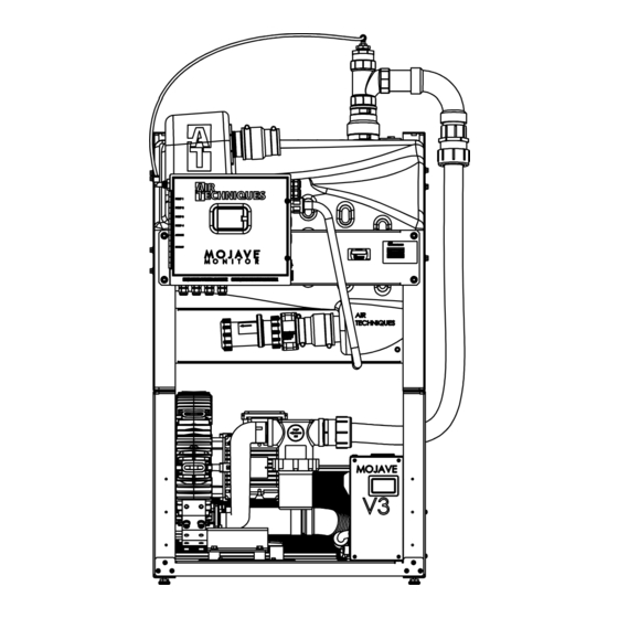
PRODUCT DESCRIPTION As shown by Figure 1, MOJAVE consists of the major components listed below . Vacuum Pump Assemblies V3M, V5M or V7M. A single-stage pump, where all of the wetted metal parts are nickel plated or stainless steel . ... -
Page 8: Main System Components
PRODUCT DESCRIPTION Power Switch with Exhaust Vent Circuit Breaker Air Inlet Port Vacuum Motor Connection *Heat with Filter Pump Harness Exchanger *Heat Exchanger Power Cable Air Inlet Port Leveling with Filter Electrical Feet Serial No.Plate MMC-M * Not included in -NHE models * Not included in -NHE models Connection V3M, V5M and V7M Vacuum Pumps... -
Page 9: Typical Mojave Functional Flow Diagram
PRODUCT DESCRIPTION Any time the power to the MOJAVE is turned OFF the tanks will automatically drain. Vacuum System Operation. Air, water, and solids from the operatory are pulled into the separator tank . Air is expelled out through the pump exhaust while liquids and solids fall to the bottom of the tank . The vacuum in the tank keeps the check valve to the drain closed and the tank gradually fills . -
Page 10: Installation Information
H5479 MT12-M 220V Tank Accessory Pack Ships with every 220V MT12-M tank H5170 MOJAVE V3M, V5M and V7M Pump Accessory Pack Ships with every V3M Pump, V5M Pump and V7M Pump MOJAVE V3M, V5M, V7M without Heat Exchanger H5307 Ships with every V3M Pump, V5M Pump and V7M Pump Pump Accessory Pack”... -
Page 11: Mojave System Component Dimensions
INSTALLATION INFORMATION Physical Characteristics Tank Three Four Master V3M, V5M or V3M, V5M or V7M V5M Pumps V5M Pumps (Two MT10-M CT20-M Controller V7M Pump Pumps Stacked Stacked Stacked Side by Side) 10 Gallon Continuum 13.5 in. (34 cm) 29 in. (74 cm) 25 in. - Page 12 INSTALLATION INFORMATION Site Requirements V3M & 2V3M & 2V5M & Master Electrical 2V7M 3V5M 4V5M 2V3MCT 2V5MCT Controller All pumps 120 or 220 Voltage Rating Volts AC 220 Volts Single Phase AC, 60 Hz olts AC or 108/132 V 198/242 Volts AC All pumps Voltage Minimum/Maximum olts AC 198/242 V...
- Page 13 INSTALLATION INFORMATION Installation Layout Space. Figure 4 shows the requirements for the installation of the various MOJAVE model configurations . Please note that all units are shipped with leveling feet set to lowest position . Heights can be increased by 1 inch by adjusting the leveling feet . Refer to Figure 5 for the recommended configuration arrangements .
-
Page 14: Mojave System Configurations
MOJAVE SYSTEM CONFIGURATIONS Important: Side by side installation of pump and tank is preferred. Stack a MT10-M tank on top of one V3M, V5M or V7M pump only if space is a problem. V3M, V5M or V7M pumps should only be stacked two high in all other system configurations as shown. All units are shipped with leveling feet set to lowest position. -
Page 15: Installation
PUMP (V3M, V5M or V7M) Note: See MOJAVE V3M, V5M and V7M Pump Accessory Pack, P/N H5170 or H5307, for required fastener hardware. Remove leveling feet from pump or tank to be stacked. Figure 6. Stacking the MT10-M Tank on Top of a MOJAVE Pump Hardware Detail 1/4-20 X 1/2"... -
Page 16: V3M, V5M And V7M System Installation
V3M, V5M and V7M MOJAVE System configuration installations using accessory packs that provide the required hoses, clamps and adapters as follows: MOJAVE V3M, V5M and V7M Pump Accessory Pack, P/N H5170 or H5307 - supplied with each pump and is used as follows . -
Page 17: Optional Mounting
INSTALLATION Installation Setup. Installation of a V3M, V5M and V7M MOJAVE system configuration consists of placing the equipment in the proper installation space and making connections between a MT10-M tank and a V3M, V5M or V7M pump . Use standard industry guidelines for working with electrical circuits, plumbing and on electronic equipment as necessary . -
Page 18: Mojave V3M/V5M/V7M Pump And Mt10-M Tank Connection Diagram
Make sure that all hose connections are straight and secure without any sharp bends or kinks. Since the vacuum hose is rigid, make sure not to stress connections especially at the pump inlet. Figure 9. MOJAVE V3M/V5M/V7M Pump and MT10-M Tank Connection Diagram, Sheet 1... - Page 19 10 MM Vent Solenoid and then to Condensation Water Shutoff Valve Drain Port Connections Open Drain Pipe To Facility Sewer Drain Tank Drain Closed Vented Assembly Drain MT10-M Tank Figure 9. MOJAVE V3M/V5M/V7M Pump and MT10-M Tank Connection Diagram, Sheet 2...
-
Page 20: 2V3M, 2V3Mct, 2V5M, 2V5Mct And 2V7M System Installations
MOJAVE V3M, V5M and V7M Pump Accessory Pack, P/N H5170 or H5307 - supplied with each pump and is used as follows . - Page 21 INSTALLATION 2V3M, 2V3MCT, 2V5M, 2V5MCT and 2V7M Connection Procedure. Using industry standard techniques, make the connections between the tank and pumps with supplied components of acces- sory packs P/Ns Dual System Installation Kit ( P/N MIK2) . Refer to H5170 or H5307 & H5210) and Figure 10, sheets 1 and 2, for the connection diagram and perform the following procedure .
- Page 22 INSTALLATION 3 . Exhaust Vent Assembly Installation . Install the Exhaust Vent Assembly (P/N H5302) to the bottom end of the facility vent line . Install a length of 1/4 inch OD Urethane Tubing (P/N 51453) between the vent condensation drain port and facility sewer drain . See Figure 10, sheet 2, item (3) .
-
Page 23: 3V5M And 4V5M System Installation
MOJAVE system configuration installations using accessory packs that provide the required hoses, clamps and adapters as follows: MOJAVE V3M and V5M Pump Accessory Pack, P/N H5170 or H5307 - use as follows . • Stack the associated MOJAVE pumps as shown by Figure 7 . -
Page 24: Pump/Tank Connection Manifold Fabrication
INSTALLATION Installation Setup. Installation of triple and quad MOJAVE system configurations consist of placing the equipment in the proper installation space, fabricating a Pump/Tank Connection Manifold and an inlet tee connector . 1 . Refer to Figures 4 and 5 and determine the installation footprint dimensions and connection requirements . -
Page 25: 3V5M Or 4V5M System Connection Detail Using Accessory Kit
INSTALLATION 2 . Tank Air Outlet to Pump Inlets Connection . Refer to Figure 12, item (2) . a . Connect 1 ½" ID, clear hose (P/N 54521) cut for installation between the compression connectors of the Pump/Tank Connection Manifold check valves and the air inlet filter of each pump . -
Page 26: Electrical Connections
Master Controller. Note 2: (2) and (3) refers to old style Air Techniques rocker switches. Do not connect (4). Note 3: Although Air Techniques supplies a remote panel switch (#53202-1) for use with the MMC-M, any remote switch can be used connected to MMC-M J13 only. All remote system status indication is lost when using switches other than switch #53202-1 provided. -
Page 27: Remote Switch Connection Options
ELECTRICAL CONNECTIONS SPDT NOT USED Important: Terminal BRN 2 is not used when BI COLOR SWITCH, 6VDC P/N 53202-1 making the 4-wire connection. View A. 4-Wire Green & Yellow Indicators 6 VDC Remote Switch Installation Terminals RED & BRN 1 are not used when making USED the 3-wire connection. - Page 28 ELECTRICAL CONNECTIONS NOT USED NOT USED Important: Terminals BRN 1 & BRN 2 are not used when making the 3-wire connection. Important: Terminals BRN 1 & 2 are not used when making the 3-wire connection. View c. 3-Wire Green indicator only 6 Vdc remote SWitch inStallation NOT USED NOT USED NOT USED...
-
Page 29: Operating Information
OPERATING INFORMATION General. The vacuum level is factory preset at 8 InHg . This vacuum set point is adjustable from 8 .0 to 10 .0 inHg in increments of 0 .5 inHg via the Master Controller . System operation is automatically controlled via the Master Controller and the Variable Frequency Drive (VFD) of each pump . - Page 30 OPERATING INFORMATION START UP BY TOUCH SCREEN 1 . Set the motor Mains Circuit Breaker in the ON position . 2 . Observe that the color touch screen illuminates and depress the blue Standby button . 3 . Observe that the Standby button changes to a green Running button, that the unit is running and Control Panel Pump Power...
-
Page 31: Touchscreen Controls
TOUCHSCREEN CONTROLS Note: The motor power circuit breaker must be kept in the ON position to operate the color LCD touch screen display. See Operating Information on page 15. All MOJAVE units have a color LCD touch screen display located on the front control box panel . This display is used to start the unit and show system operating status . - Page 32 TOUCHSCREEN CONTROLS 1. HOME SCREEN a . STANDBY BUTTON / VACUUM SCREEN Standby Button - Running: Motor and separator run to maintain the set vacuum level of 8 .0 to 10 .0 inHg . - Standby: Motor and separator are not running . - Error: Motor and separator do not run .
- Page 33 Scroll Button 2. SETTINGS SCREEN a . INFORMATION Model - Air Techniques model number . ii. SN - Unit serial number . iii. PCB - Indicates control board serial number . iv. Firmware - Indicates latest installed firmware and revision .
- Page 34 TOUCHSCREEN CONTROLS Time Zones Currently Being Used in United States Time Zone Time Example Offset City Abbreviation Name UTC - 5 Eastern Standard Time New York UTC - 6 Central Standard Time Chicago UTC - 7 Mountain Standard Time Salt Lake City UTC - 8 Pacific Standard Time Los Angeles...
- Page 35 TOUCHSCREEN CONTROLS ALARMS MOJAVE checks operation via the Intelligent Monitoring System and alerts the user to problems by displaying Warnings or Errors in the upper left corner of the Home Screen . Warnings notify the user of conditions effecting operation while Errors are critical problems disabling operation . As shown below, explanation of the Warning or Error is expanded by pressing the displayed alert .
- Page 36 TOUCHSCREEN CONTROLS b . ERRORS Pressure sensor is malfunctioning. Readings are Pressure Sensor consistently negative. The Vacuum level has been 1 inHg above the set-point High Vacuum for 1 minute. A Pump VFD has reported an error via its relay contact. A Pump is running that the Master Controller did not Control instruct to run.
-
Page 37: Operation
OPERATION Initial System Startup. Start the MOJAVE system for the first time by referring to the Operating Information section and performing the following procedure . Important: Make sure that each facility electrical disconnect box controlling the 220V, 20 AMP single phase 50/60 Hz circuit to the corresponding pump is set to the ON position. 1 . -
Page 38: Troubleshooting
TROUBLESHOOTING Automated Self Diagnostic Feature. Every 2 hours each pump in the system that is not ON will be turned ON for 6 seconds and then turned OFF, one at a time . By constantly checking the status of all pumps in the system this feature makes sure that each is ready for operation and may be helpful in preventing locked rotors . - Page 39 TROUBLESHOOTING Problem Possible Cause Possible Solutions 1. Tank does not a. Gate Valve in closed position. a. Open Gate Valve fully. drain. b. Drain check valve clogged. b. Call your authorized dealer for repair service. c. Clogged drain. c. Call your local plumber. d.
-
Page 40: Vision Monitor Remote Monitoring Solution
Vision Monitor Remote Monitoring Solution Vision Monitor is a cloud based remote monitoring solution that provides valuable, real-time status information from your network connected Mojave Monitor directly to any internet devices via the web interface or mobile app . Connect your equipment to allow service technicians to quickly diagnose problems, update parameters remotely, check usage history, and minimize downtime . -
Page 41: Maintenance
MAINTENANCE Initial Maintenance. After installation, clean the vacuum lines with CleanStream Cleaner . This is especially necessary when a new system is being installed into existing dental system piping . Using CleanStream Cleaner helps the MOJAVE system to remove any built up deposits in the piping system . Perform the initial cleaning by performing the daily maintenance procedure provided below . - Page 42 MAINTENANCE WARNING! Always use the proper personal protective equipment when in contact with biohazard waste. Caution: The use of the following materials will result in equipment damage, loss of system performance and/or will void the warranty. DO NOT USE: Foaming cleaners Household cleaning agents Instrument cleaners/disinfectants Cleaning agents containing chlorine...
-
Page 43: Replacement Parts
MAINTENANCE 2 Liter Dispenser High Volume Evacuator (HVE) Position 1 Liter Dispenser Position Saliva Ejector (SE) Figure 16. CleanStream Dispenser Cap Adaptor Locations Important Information Tank Disposal • DO NOT send used contaminated tank back to ATI. • Every contaminated tank must be disposed of in accordance with local codes, regulations and guidelines for biohazard material handling and disposal. -
Page 44: Accessories/Options
. Warranty is void if equipment is installed or serviced by other than dealer service personnel authorized by Air Techniques . Air Techniques, Inc . is not liable for indirect or consequential damages or loss of any nature in connection with this equipment . - Page 45 NOTES...
- Page 46 NOTES...
- Page 47 NOTES...
- Page 48 For over 50 years, Air Techniques has been a leading innovator and manufacturer of dental products . Our priority is ensuring complete satisfaction by manufacturing reliable products and providing excellent customer and technical support . Whether the need is digital imaging, utility room equipment or merchandise, Air Techniques can provide the solution via our network of authorized professional dealers .
Need help?
Do you have a question about the Mojave V3M and is the answer not in the manual?
Questions and answers