
Related Manuals for multivac C 500


Summary of Contents for multivac C 500
-
Page 1: Instruction Manual C 500
Instruction manual C 500 Instruction manual C 500 Betriebsanleitung 07.06.2005 1/43 ba_c500_50s2GB06IVZ.fm... -
Page 2: Control Panel
Control panel Control panel I / O mbar STOP 1.11 1.10 1.9 1.7 1.6 Control panel, control unit CONTROL UNIT ON/OFF key Digital display Display value in millibar Display value in seconds PROGRAM keys 1 to 6 INCREASE VALUE key DECREASE VALUE key SEALING key INERT GAS key (optional) -
Page 3: Elements Of The Machine
Elements of the machine Elements of the machine Front view Control panel, control unit Water outlet Main switch Water inlet Sealing bars Electrical connection Cover seal Electrical connection Counter-pressure bars Vacuum pump oil filling screw Inert gas nozzles Vacuum pump oil inspection glass Compressed air connection Oil cooler drain screw Inert gas connection... -
Page 4: Table Of Contents
Elements of the machine Contents Instruction manual C 500 ............. 1 Control panel ................. 2 Elements of the machine ............3 Manufacturer, service address, user information ....5 Use ..................6 Safety ..................7 Electromagnetic Compatibility (EMC) ..........8 Operation with inert gas ..............8 Transport, Set-up, Putting into operation ...... -
Page 5: Manufacturer, Service Address, User Information
Safety information – Where should I be particularly careful? Information - what else is to be said Copying or lending of this instruction manual or extracts thereof to third parties is only allowed with the express permission of MULTIVAC. Betriebsanleitung 07.06.2005 5/43 ba_c500_50s2GB06.fm... -
Page 6: Use
Misuse excludes the manufacturer from any liability! The risk is borne by the plant operator alone. Avoidable incorrect use – Use of externally purchased articles, e.g. non-original MULTIVAC spare parts. – Incorrect operation. Example: Sealing times that are too short or too long result in the film pouches not being closed securely and thus damage the product. -
Page 7: Safety
Safety Safety General Safety Notes Dangerous contact voltage! Making contact with voltage-carrying parts can lead to severe injury, even death. Only qualified electricians are permitted to make repairs to the electrical equipment. Switch off the machine before conducting any repair work. Turn the main switch to 0 and lock it to prevent accidental start-up. -
Page 8: Electromagnetic Compatibility (Emc)
Safety Electromagnetic Com- Chamber machines are designed for use in domestic, business and trade sectors (without the use of an individual transformer, running from the pub- patibility (EMC) lic electric power supply). If employed in the industrial sector, a limitation of the operating characteristics may occur. -
Page 9: Transport, Set-Up, Putting Into Operation
Transport, Set-up, Putting into operation Transport, Set-up, Putting into operation Set-up – Note the weight of the machine, see "Technical data". – Use suitable lifting equipment or have somebody else to assist you. – Unpack the machine. – Check there has been no damage caused during transport. –... - Page 10 Transport, Set-up, Putting into operation Electrical Connection – Read the nominal voltage from the nameplate. Does it conform to the power supply voltage? Typ/Model N e t z s i c h e r u n g Ser. No. E x t e r n a l f u s e Bauj./Year If the rotational directon is incorrect, the vacuum pump can be destroyed, –...
-
Page 11: External Vacuum Connection (Option)
Transport, Set-up, Putting into operation External vacuum Note on vacuum connection connection (Option) When equipped with: External vacuum connection – Use vacuum hose with internal diameter of 60 mm. Max. hose length 3 m. max. 3 m max. 3 m Di 60 mm Betriebsanleitung 07.06.2005... -
Page 12: Cooling Water Connection (Optional)
Transport, Set-up, Putting into operation Cooling water Note on cooling water connection connection (optional) When equipped with: Water cooling system Water infeed (infeed pressure max. 6 bar) Water drain Use a 1/2" water supply line for new installations. Blow out supply line thoroughly before putting into operation. The water drain should run downwards so that no remaining water can flow backwards. - Page 13 This leads to deposits and, in the worst case, blockage of the water line. The ideal pH value is between 6 and 7. When installing a return cooling cir- cuit, please consult MULTIVAC or its representatives. Cooling water requirements – For water pressure: 1 bar -->...
-
Page 14: Pressurised Air Connection
Transport, Set-up, Putting into operation Pressurised air connection For special cases, e.g. when packaging hot liquids or with high pressure gas flushing of the packaging, a compressed air connection is installed to increase the sealing force (see Fig.). Without compressed air connection: Sufficient sealing force is only obtained with a final pressure of under 400 mbar. -
Page 15: Inert Gas Connection
Transport, Set-up, Putting into operation Inert gas connection Note the safety instructions. Caution! The gas input pressure must not exceed 3 bar. – Connect a gas hose with an internal diameter of 8 mm (max. length: 5 m) from the pressure reducer (B) of the gas tank to the nipple. –... -
Page 16: Operation
Operation Operation Packing – First steps Start up – Press I/O button. – The LED (light-emitting diode) lights up. I /O – Machine is ready for operation. The digital display shows current air pressure, e.g. 931 mbar. LED "mbar" lights up. Note: Values over 999 mbar cannot be displayed. -
Page 17: Recommended Settings
Determine the correct settings by experimentation, see "Setting recommendations" and "Displaying values, changing values". – If the factory settings have to be changed and newly stored on Program 1, please contact MULTIVAC. Recommended Settings Sealing The standard pouch "PA/PE", thickness 100 µm, is best suited for most gastronomic products. - Page 18 Operation Target vacuum guidelines for: Veg. Cheese Meat Soup, Sauces etc. 80°C 40°C To Be Noted When Using Liquid Products: Vacuum lowers the boiling point of liquids. Liquids boil at a lower tempera- ture under a vacuum, which makes itself noticeable through the formation of bubbles in the pouch.
- Page 19 Operation Finding the Pressure Value of Liquid Products – Set "Auto" mode: Press REDUCE VALUE button until "Auto" appears. – Start Evacuation. – Observe the time at which bubbles form. – Press VACUUM QUICKSTOP button. STOP – Note displayed pressure value, raise this by 10 mbar and input as set- ting.
- Page 20 Operation Putting the Filler Plates and Filled Pouches in the Chamber The filler plates should reduce the volume of the chamber which is to be evacuated and correctly position the pouch on the sealing bar. The pouch collar should lie at about mid-height of the pouch level. Thus folds in the sealing seam can be avoided.
- Page 21 Operation Close lid, wait until the end of the cycle, remove pouch – Close lid and press down until it is held down by the vacuum generat- – The following processes function automatically: – The vacuum pump starts. – The lid is sucked down until it is fixed in place. –...
-
Page 22: Check Pouch
Operation Check pouch Check tightness Check the sealed pouch for tightness. A leaky pouch is caused by: – A leaky seal seam: – Pouch is dirty in the seal seam area. – Sealing time is too short. – Damage to the pouch: –... - Page 23 Operation Check sealing Check whether the seal seam is perfect. Otherwise air can infiltrate the pouch. This worsens the durability of the product. Separating excess pouch film Can be done easily: – The sealing time setting is correct! Not possible: –...
-
Page 24: Displaying Values, Changing Values
Operation Displaying values, Pressure indicator changing values Lid opened: Display of the external air pressure, e.g., 960 mbar (max. of 999 mbar can be displayed). Lid closed: Display of pressure in chamber, e.g., from 960 to 5 mbar. mbar Displaying or changing the pressure setting Significance of the pressure setting: –... -
Page 25: Displaying Or Changing The Post-Evacuation Time
Operation To change: – As long as the display blinks, press one of the keys INCREASE VAL- UE, DECREASE VALUE. The display changes in steps of 1 mbar. If the key is held down, the value changes in larger steps. Setting the automatic operation "Auto": –... -
Page 26: Displaying Or Changing The Sealing Time
Operation – To change: As long as the display blinks, press one of the keys IN- CREASE VALUE, DECREASE VALUE. The display changes in steps of 1 second. If the key is held down, the value changes in larger steps. Displaying or changing the sealing time The heat for sealing the pouches is caused by a momentary electrical power current through the sealing wire. -
Page 27: Displaying Or Changing Separation Time
Operation Displaying or changing separation time The heat for separation is created by a temporary flow of electrical current through the separation bar. Thin pouches require a lower separation time, thick ones more. Recom- mendation for standard pouches (PA/PE): 1.4 seconds –... -
Page 28: Displaying Or Changing The Inert Gas Value
Operation Displaying or changing the inert gas value – Press the INERT GAS key. – Displaying or changing the inert gas value Press the INERT GAS key. mbar To change: – As long as the display blinks, press the INCREASE VALUE or DE- CREASE VALUE key. -
Page 29: Calling Up Or Saving A Program
Operation Calling up or saving a program The control unit has 6 program memories. The memory position P 1 contains the factory settings. It cannot be used for saving other settings. The remaining five memory positions P 2 to P 6 can contain settings for pressure, sealing, etc.. - Page 30 Operation Saving the program (Example: to memory position P 5) This process writes over possibly existing settings. The current settings (pressure, sealing) which were just being used, should be saved to the P 5 memory position. To do this: – Press the P 5 key and keep it held down. –...
-
Page 31: Care And Maintenance
)tension springs may only be replaced by the MULTIVAC service or- ganisation). Note If it is necessary that the pressure is maintained exactly, the built-in pres- sure sensor should be calibrated yearly. To do this, please contact the customer service. -
Page 32: Cleaning
Care and maintenance Cleaning Safety Danger of corrosive burns! The cleaning agents are strongly corrosive. The corrosive effects are not immediately noticed. Therefore, wear rubber gloves and protective glasses when handling cleaning agents. Observe the safety information on the cleaning agents. Danger of fire! Alcohol disinfectant is readily flammable. -
Page 33: Disinfection - Corrosion Protection
Care and maintenance Pre-cleaning – Remove the power plug from the socket. – Remove coarse dirt: Remove all coarse contamination by hand, such as meat remains. Main cleaning – Get the cleaning agent concentration from the cleaning agent specifi- cations. –... -
Page 34: Care Products
Care and maintenance Care products MULTIVAC recommends the following cleaning agents, disinfectants, corrosion protection agents and decalcifiers. Manufacturer Ecolab Johnson Finktec Optimol Diversey Europe Cleaning and P3-steril – JD Delladet FINK-FC – disinfecting 2062 agents Cleaning agents, P3-topax 12 Quorum... -
Page 35: Replacing The Cover Seal
Care and maintenance Replacing the cover Important information seal Danger! There is a danger of injuries due to the swinging movement of the cover. Do not allow anyone else near the danger area! Only move the cover using the handle (1), not the levers (2). When changing the lid seal, note that: –... -
Page 36: Trouble-Shooting
Trouble-shooting Trouble-shooting Poor vacuum or poor sealing could result from incorrectly set settings (un- intended). Always note: If a program key is pressed longer than approx. 3 seconds, the saved set- tings are over-written. Problem Cause Solution Machine is not running. –... - Page 37 Trouble-shooting Problem Cause Solution The pre-set pressure is – There is too little or dirty oil in the – Pour in oil or renew --> Appen- not reached. vacuum pump. Possibly caused dix. by evacuating moist, hot prod- ucts; steam prevents reaching the pressure setting.
- Page 38 Trouble-shooting Error code Cause Solution "Er 4" error code is dis- – measuring line to the pressure – Clean measuring line, repla- played. sensor is obstructed or the filter ce filter. is clogged. – Pressure sensor is defective. – Replace pressure sensor. –...
-
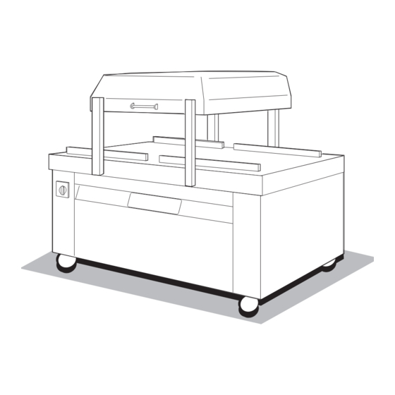
Page 39: Technical Data
Technical data Technical data 1320 1600 1050 Height (lid open): 1320 mm Height (lid closed): 1065 mm Width: 1600 mm Depth: 1050 mm Electric voltage: see type plate Permitted operating temperature range: 0...45°C Permitted temperature range for storing the machine: -25...+85°C Relative humidity: 5...85 %, Non-condensing... -
Page 40: Special Equipment
Special equipment Special equipment MHP-evacuation time VACUUM key (with MHP option, can be fitted by MULTIVAC customer service) This operating mode is best used for products with air pockets, such as: – Packaged meals – Liver pâté – Uncooked ham –... - Page 41 Special equipment INPUTS – Press repeatedly until: – Change from post-evacuation time (s) to MHP evacuation time (s). – The MHP evacuation time appears in the digital display. – Change setting: – Press key. Note: Setting range 0.0–15 seconds Enter 0.0 s --> MHP function switched off. –...
-
Page 42: Working Area Sound Pressure Level
Basis: DIN EN ISO 3744/3746 and 11 204 Measuring unit: Precision sound level meter DIN 45 633 IEC 651, class 1, Dynamic characteristics: slow. Applicable accuracy class: 2 Machine type: C 500 in new condition. Measured values Working area sound pressure level L in dB (A) -
Page 43: Assembly Instructions, Repair Kit, Sealing Equipment
Assembly instructions, repair kit, sealing equipment Assembly instructions, repair kit, sealing equipment Note Observe the safety instructions on page 7. Sealing bar Counter-pressure bar Betriebsanleitung 07.06.2005 43/43 ba_c500_50s2GB06.fm...
Need help?
Do you have a question about the C 500 and is the answer not in the manual?
Questions and answers
Que parte necesito ordenar para una c500 que solo se activa el vaccuun y celado hacia el lado izquierdo y cuando se mueve al lado derecho solo ase un sonido de fuga del aire dando herror 69
The issue with the Multivac C 500, where vacuum and sealing only activate on the left side and an air leak sound with error 69 occurs when moved to the right side, suggests a problem with the air de-oiling component or a faulty valve related to the vacuum system. You may need to order a replacement air de-oiling component and check the oil return flow valve as mentioned in the manual. Additionally, inspect the sealing bar and chamber components for misalignment or leaks.
This answer is automatically generated
Tengo una multinacional c500 que por rato deja de sellar cuál puede ser la causa y que pieza debo ordenar
A Multivac C 500 could stop sealing intermittently due to several possible causes:
1. Insufficient Pressure – If the pressure is below 400 mbar, the sealing force may be inadequate. Check and correct the settings.
2. Improper Sealing Time – The sealing time may be set incorrectly. Adjust to the correct time.
3. Unsuitable Pouch – Ensure that the pouch used is capable of being sealed.
4. Pouch Neck Placement – If the pouch neck is squeezed by the lid, reposition it within the chamber.
5. Damaged or Dirty Lid Seal – If the lid seal is dirty, clean it. If it is damaged, replace it.
6. Misadjusted Lid – Adjust the lid if necessary.
7. Worn Teflon Strip or Sealing Bar – If the Teflon strip or sealing bar is worn or damaged, it should be replaced.
The part that may need to be ordered is the lid seal or Teflon strip/sealing bar, depending on the observed issue.
This answer is automatically generated