Advertisement
Quick Links
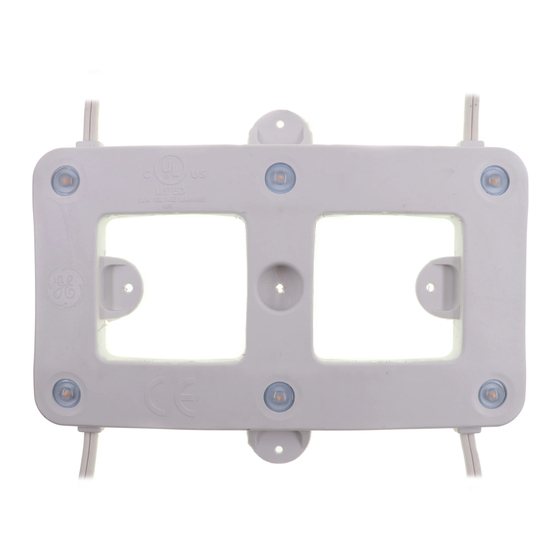
GE
Lighting
Tetra
PowerGrid - Gen 3
®
LED ARCHITECTURAL SERIES
Product Codes
93013528, 93013522, 93013523, 93013524
LED System Features
• Certified to UL 2108
• Low-Voltage Luminaire (24 VDC)
• IP54, dry or damp location rated.
• Compatible with 24 Volt GE LED Drivers
• Dimmable with GE 0-10V Dimming LED Driver or GE
Dimming Module and compatible dimming controller
For use in the following applications
• Backlighting
• Illuminated Walls or Ceilings
Save These Instructions
This product is intended solely for the use of non-
residential architecture lighting and is not intended for
use in any other applications.
imagination at work
BEFORE YOU BEGIN
Read these instructions completely and carefully
WARNING/AVERTISSEMENT
Risk of electrical shock. Disconnect power before servicing or
installing product.
Risque de choc électrique. Couper l'alimentation avant le
dépannage ou avant l'installation du produit.
Prepare Electrical Wiring
Electrical Requirements
• Do not use in wet locations.
• The grounding and bonding of the LED Driver shall be
done in accordance with National Electric Code (NEC)
Article 600.
• Follow all National Electric Codes (NEC) and local codes.
Installation Guide
Advertisement

Related Manuals for GE Tetra PowerGrid-Gen 3


Summary of Contents for GE Tetra PowerGrid-Gen 3
- Page 1 • Compatible with 24 Volt GE LED Drivers Risk of electrical shock. Disconnect power before servicing or installing product. • Dimmable with GE 0-10V Dimming LED Driver or GE Risque de choc électrique. Couper l’alimentation avant le dépannage ou avant l’installation du produit.
- Page 2 Determine Layout Determine total number of modules needed to populate the application area based on width and height. Refer to estimating charts below. NOTE: For optimal light uniformity, application depth should be a minimum of 3 inches (76 mm). A mock-up using the PowerGrid module and panel to be illuminated is highly recommended.
- Page 3 Using the diagram below as an estimation guide, begin cutting strings of modules to create 8-inch (203 mm) tall rows and 12-inch (305 mm) wide columns. Modules should be 2 inches (51 mm) from the edge of the application with 2.77 inches (70 mm) between each column.
- Page 4 GE and the GE Monogram are trademarks of the General Electric Company. All other trademarks are the property of their respective owners. Information provided is subject to change without notice. All values are design or typical values when measured under laboratory conditions. GE Lighting is a business of the General Electric Company. © 2016 GE.