Advertisement
Available languages
Available languages
Quick Links
上海菱本电子科技有限公司
-B10
DOP
Instrunction Sheet
(1) Preface
Thank you for purchasing DELTA's DOP-B series. This instruction sheet will be helpful in the
installation, wiring and inspection of Delta HMI. Before using the product, please read this
instruction sheet to ensure correct use. You should thoroughly understand all safety
precautions before proceeding with the installation, wiring and operation. Place this instruction
sheet in a safe location for future reference. Please observe the following precautions:
Install the product in a clean and dry location free from corrosive and inflammable
gases or liquids.
Ensure that all wiring instructions and recommendations are followed.
Ensure that HMI is correctly connected to a ground. The grounding method must
comply with the electrical standard of the country (Please refer to NFPA 70: National
Electrical Code, 2005 Ed.).
Do not disassemble HMI, modify or remove wiring when power is applied to HMI.
Do not touch the power supply during operation. Otherwise, it may cause electric
shock.
If you have any questions during operation, please contact our local distributors or Delta sales
representatives.
The content of this instruction sheet may be revised without prior notice. Please consult our
distributors or download the most updated version at http://www.delta.com.tw/ia.
(2) Pin Definition of Serial Communication
DOP-B10S411 / DOP-B10S511/ DOP-B10E515 COM1 Port
COM Port
PIN
1
PIN1
2
3
4
5
6
7
8
9
Note1: Blank = To avoid malfunction, it must be left unconnected.
DOP-B10S411 / DOP-B10S511 COM2 Port
COM Port
PIN
COM2
RS-232 RS-232 RS-485 RS-485
1
PIN1
2
RXD
3
TXD
4
5
6
7
8
9
Note1: Note1: Blank = To avoid malfunction, it must be left unconnected.
Note2: DOP-B10S411 / DOP-B10S511 models do not support RS-422 flow control.
DOP-B10E515 COM2 Port
COM Port
PIN
1
PIN1
2
3
4
5
6
7
8
9
Note1: Note1: Blank = To avoid malfunction, it must be left unconnected.
Note2: When COM2 port is used for RS-232 flow control (RTS, CTS is set), COM3 port cannot
be used.
Note3: When COM2 port is used for RS-422 flow control, for the pin settings it needs, please
refer to the pin definitions of MODE 2 in DOP-B10E515 COM3 port table.
DOP-B10E515 COM3 Port
COM Port
PIN
1
PIN1
2
3
4
5
6
7
8
9
Note1: Note1: Blank = To avoid malfunction, it must be left unconnected.
Note2: When COM2 port is used for RS-422 flow control, for the pin settings it needs, please
refer to the pin definitions of MODE 2 in DOP-B10E515 COM3 port table.
上海菱本电子科技有限公司
High Color‧Wide Screen‧
User-Friendly HMI Products
No.18, Xinglong Rd., Taoyuan City
33068, Taiwan
MODE1
RS-232
RXD
TXD
GND
RTS
CTS
MODE1
MODE2
COM3
COM2
COM3
COM2
D+
D+
GND
GND
D-
TXD
RXD
D-
MODE1
MODE2
RS-232
RS-422
TXD+
RXD
TXD
RXD+
GND
GND
TXD-
RTS
CTS
RXD-
MODE1
MODE2
RS-232
RS-422
TXD+(RTS+)
RXD
TXD
RXD+(CTS+)
GND
GND
TXD-(RTS-)
RXD-(CTS-)
服务热线:400 821 3454
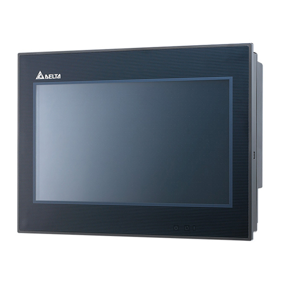
(3) Parts Names
DOP-B10S411 (Front View)
A
Power LED Indicator (
B
Touch Screen / Display
DOP-B10S411 (Rear View)
A
MODE3
B
COM3
-
RS-422
TXD+
A
Power Input Terminal
B
COM2
RXD+
GND
TXD-
C
COM1
RXD-
DOP-B10S511 / DOP-B10E515 (Front View)
MODE3
RS-485
D+
GND
D-
MODE3
RS-485
D+
A
Power LED Indicator (
Operation LED Indicator (
B
GND
/Alarm LED Indicator (
D-
C
Touch Screen / Display
Please note that DOP-B10S511 model only has Power LED Indicator (A) and
Touch Screen / Display (C).
服务热线:400 821 3454
A
)
Note:
Lights in green when HMI works normally.
E
C
D
USB Slave
E
USB Host
Please note DOP-B10S411 model has
not system key, user could press at
blank space for 3 seconds, and then will
hear Buzzer sound. After hearing the
Buzzer sounded, please press left top
corner to enter system menu.
A
)
Lights in green when HMI works normally.
Lights in blue: the communication is carried out
)
/ the data is accessing. (Please refer to the "Note"
below for explanation).
)
Lights in red: one of the alarms is on.
Note: The definition of the operation LED indicator
(Blue) can be determined by the users freely.
B
D
C
B
Advertisement

Related Manuals for Delta DOP-B10 Series


Summary of Contents for Delta DOP-B10 Series
- Page 1 Instrunction Sheet (1) Preface Thank you for purchasing DELTA’s DOP-B series. This instruction sheet will be helpful in the installation, wiring and inspection of Delta HMI. Before using the product, please read this instruction sheet to ensure correct use. You should thoroughly understand all safety precautions before proceeding with the installation, wiring and operation.
-
Page 2: Specifications
4) Some models are in the process of application to UL and KCC certification. For more information, please consult our distributors. 5) The content of this instruction sheet may be revised without prior notice. Please consult our distributors or download the most updated version at http://www.delta.com.tw/ia. 上海菱本电子科技有限公司 服务热线:400 821 3454... -
Page 3: Parça İsimleri
33068, Taiwan Bilgi Dokümanı (1) Önsöz DELTA’nın DOP-B serisi operatör panellerini seçtiğiniz için teşekkürler. Bu bilgi dokümanı Delta HMI kurulum, bağlantı, bakım ve kontrolünde kullanıcıya yardımcı olacaktır. Doğru kullanım için ürünü kullanmadan önce bu dokümanı mutlaka okuyunuz. Kurulum, bağlantı ve çalışma yapmadan önce güvenlik uyarılarını... - Page 4 DOP-B10S511 / DOP-B10E515 (Arka Görünüm) Display Ölçü 219.6 x 131.76mm 211.2 x 158.4mm 211.2 x 158.4mm İşletim Sistemi Delta Real Time OS 32-bit RISC Mikro-işlemci Flash ROM 128 MB Flash ROM (OS Sistem: 30MB / Backup: 16MB / Kullanıcı Uygulama: 82MB) SDRAM...
- Page 5 National Electrical Code, 2005 Ed.) 。 在通電時,請勿拆解人機介面或更改配線。 在通電運作時,請勿接觸電源處,以免觸電。 電源指示燈( ) 註: 綠燈亮:正常運作 如果您在使用上仍有問題,請洽詢經銷商或者本公司客服中心。由於產品精益求精,當內容規格有所修 正時,請洽詢代理商或至台達網站(http://www.delta.com.tw/ia)下載最新版本。 操作/顯示區域 (2) 通訊腳位定義 DOP-B10S411 / DOP-B10S511 / DOP-B10E515 COM1 定義 DOP-B10S411 (背面) MODE1 COM Port 示意圖 腳位 RS-232 PIN1 註:空白=請勿接線,避免造成誤動作 DOP-B10S411 / DOP-B10S511 COM2 定義...
- Page 6 LED Back Light(常溫 25 顯示範圍 219.6 x 131.76mm 211.2 x 158.4mm 211.2 x 158.4mm 作業系統 Delta Real Time OS 中央處理器 32-bit RISC Micro-controller 記憶體 ROM Flash ROM 128 MB(OS System: 30MB / Backup: 16MB / User Application: 82MB) 內部記憶體 64Mbytes 斷電保持記憶體...
- Page 7 National Electrical Code, 2005 Ed.) 。 在通电时,请勿拆解人机界面或更改配线。 在通电运作时,请勿接触电源处,以免触电。 如果您在使用上仍有问题,请咨询经销商或者本公司客服中心。由于产品精益求精,当内容规格有所修 电源指示灯( ) 注: 绿灯亮:正常运作 正时,请咨询代理商或至台达网站(http://www.delta.com.tw/ia)下载最新版本。 (2) 通讯脚位定义 操作/显示区域 DOP-B10S411 / DOP-B10S511/DOP-B10E515 COM1 定义 MODE1 COM Port 示意图 脚位 DOP-B10S411 (背面) RS-232 PIN1 注:空白=请勿接线,避免造成误动作 DOP-B10S411 / DOP-B10S511 COM2 定义...
- Page 8 LED Back Light(常温 25 显示范围 219.6 x 131.76mm 211.2 x 158.4mm 211.2 x 158.4mm 作业系统 Delta Real Time OS 中央处理器 32-bit RISC Micro-controller 存储器 ROM Flash ROM 128 MB(OS System: 30MB / Backup: 16MB / User Application: 82MB) 内部存储器 64Mbytes 断电保持存储器...
Need help?
Do you have a question about the DOP-B10 Series and is the answer not in the manual?
Questions and answers