Sony TMR-IF130 Service Manual
Hide thumbs
Also See for TMR-IF130:
- Operating instructions manual (32 pages) ,
- Service manual (6 pages)
Advertisement
Quick Links
TMR-IF130/IF230R
TMR-IF130/IF230R
SERVICE MANUAL
SERVICE MANUAL
TMR-IF130 is the component model block one in MDR-IF130K.
TMR-IF130 is the component model block one in MDR-IF130K.
TMR-IF230R is the component model block one in MDR-IF230RK.
TMR-IF230R is the component model block one in MDR-IF230RK.
COMPONENT MODEL NAME FOR MDR-IF130K/IF230RK
COMPONENT MODEL NAME FOR MDR-IF130K/IF230RK
MDR-IF130K
MDR-IF130K
MDR-IF230RK
MDR-IF230RK
Cordless Stereo Headphones
Cordless Stereo Headphones
MDR-IF230
MDR-IF230
MDR-IF230
MDR-IF230
Transmitter
Transmitter
TMR-IF130
TMR-IF130
TMR-IF230R
TMR-IF230R
General
General
Modulation system
Modulation system
Carrier frequency
Carrier frequency
Frequency response 18 – 22,000Hz
Frequency response 18 – 22,000Hz
Power source
Power source
UK model
UK model
AEP model
AEP model
Audio input
Audio input
Dimensions
Dimensions
Mass
Mass
Design and specifications are subject to change without notice.
Design and specifications are subject to change without notice.
MICROFILM
MICROFILM
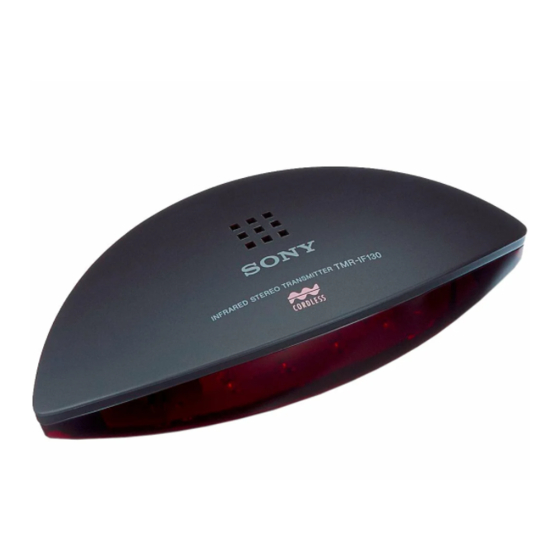
AEP Model
AEP Model
Illustration : TMR-IF230R
Illustration : TMR-IF230R
SPECIFICATIONS
SPECIFICATIONS
Frequency modulation
Frequency modulation
Right 2.8MHz
Right 2.8MHz
Left 2.3MHz
Left 2.3MHz
DC IN 9V jack accepts power supplied from the AC
DC IN 9V jack accepts power supplied from the AC
power adaptor for use on the following voltages:
power adaptor for use on the following voltages:
Operating voltage
Operating voltage
230 - 240V AC,50Hz
230 - 240V AC,50Hz
220 - 230V AC,50Hz
220 - 230V AC,50Hz
Phono jacks/stereo mini jack
Phono jacks/stereo mini jack
Approx. 152 x 40 x 72mm
Approx. 152 x 40 x 72mm
(6 x 1
(6 x 1
1
1
/
/
x 2
x 2
3
3
/
/
in.) (w/h/d)
in.) (w/h/d)
2
2
4
4
Approx. 85g (3.0oz.)
Approx. 85g (3.0oz.)
INFRARED TRANSMITTER
INFRARED TRANSMITTER
NOTE :
NOTE :
1. The adjustments should be performed in the order given.
1. The adjustments should be performed in the order given.
2. The adjustments and measurements should be perfomed for both
2. The adjustments and measurements should be perfomed for both
L-ch and R-ch unless otherwise indicated.
L-ch and R-ch unless otherwise indicated.
3. L-ch adjustment should be completed before performing R-ch
3. L-ch adjustment should be completed before performing R-ch
UK Model
UK Model
adjustment.
adjustment.
OSCILLATING FREQUENCY Adjustment
OSCILLATING FREQUENCY Adjustment
Procedure :
Procedure :
No signal state.
No signal state.
1. Connect the frequency counter to TP (CL4) (L-ch) and TP (CL-
1. Connect the frequency counter to TP (CL4) (L-ch) and TP (CL-
54) (R-ch).
54) (R-ch).
2. Adjust with RV1 (L-ch) and RV2 (R-ch) so that the reading on
2. Adjust with RV1 (L-ch) and RV2 (R-ch) so that the reading on
the frequency counter becomes the specified value.
the frequency counter becomes the specified value.
Specified Value:
Specified Value:
2.3MHz ±2kHz
2.3MHz ±2kHz
L-ch
L-ch
RV1
RV1
2.8MHz ±2kHz
2.8MHz ±2kHz
R-ch
R-ch
RV2
RV2
Connection Points and Adjustments Location :
Connection Points and Adjustments Location :
(Conductor side)
(Conductor side)
[TX BOARD]
[TX BOARD]
regulated dc
regulated dc
power suppluy
power suppluy
9 Vdc
9 Vdc
(Component side)
(Component side)
[TX BOARD]
[TX BOARD]
SECTION 1
SECTION 1
ELECTRICAL ADJUSTMENT
ELECTRICAL ADJUSTMENT
frequency counter
frequency counter
TP
TP
TP
TP
(CL4)
(CL4)
(CL54)
(CL54)
(L-ch)
(L-ch)
(R-ch)
(R-ch)
TP
TP
(CL4)
(CL4)
TP
TP
(CL54)
(CL54)
RV1
RV1
RV2
RV2
(L-ch)
(L-ch)
(R-ch)
(R-ch)
Oscillating frequency
Oscillating frequency
adjustment
adjustment
– 2 –
– 2 –
Advertisement

Related Manuals for Sony TMR-IF130


Summary of Contents for Sony TMR-IF130
- Page 1 Connection Points and Adjustments Location : frequency counter frequency counter TMR-IF130 is the component model block one in MDR-IF130K. TMR-IF130 is the component model block one in MDR-IF130K. TMR-IF230R is the component model block one in MDR-IF230RK. TMR-IF230R is the component model block one in MDR-IF230RK.
-
Page 3: Schematic Diagram
TMR-IF130/IF230R TMR-IF130/IF230R 2-2. SCHEMATIC DIAGRAM 2-2. SCHEMATIC DIAGRAM IC BLOCK DIAGRAM IC BLOCK DIAGRAM IC11 TA2061AF-EL IC11 TA2061AF-EL LEVEL LEVEL VREF VREF DET. DET. Note: Note: • All capacitors are in µF unless otherwise noted. pF: µµF • All capacitors are in µF unless otherwise noted. pF: µµF •... -
Page 4: Section 3 Exploded View
SECTION 3 SECTION 3 SECTION 4 SECTION 4 CHARGE CHARGE EXPLODED VIEW EXPLODED VIEW ELECTRICAL PARTS LIST ELECTRICAL PARTS LIST NOTE : NOTE : NOTE : NOTE : • -XX, -X mean standardized parts, so they • -XX, -X mean standardized parts, so they •... - Page 5 Ref. No. Ref. No. Part No. Part No. Description Description Remark Remark 1-216-043-91 MET AL CHIP 1-216-043-91 MET AL CHIP 6.8K 6.8K 1/10W 1/10W 1-216-338-11 RES,CHIP 1-216-338-11 RES,CHIP 1/10W 1/10W 1-216-596-11 RES,CHIP 1-216-596-11 RES,CHIP 2.7K 2.7K 1/10W 1/10W 1-216-053-00 MET AL CHIP 1-216-053-00 MET AL CHIP 1.5K 1.5K...
- Page 6 TMR-IF130/IF230R TMR-IF130/IF230R 98C027546-1 98C027546-1 Sony Corporation Sony Corporation Printed in Hungary © 1998.3 Printed in Hungary © 1998.3 9-923-357-11 9-923-357-11 Personal A&V Products Company Personal A&V Products Company Published by Quality Engineering Dept. Published by Quality Engineering Dept. – 10 –...