Table of Contents
Advertisement
Quick Links
78800681 / Rev. 5 / 31.03.2014
Operation Manual
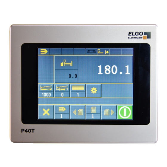
SERIES P40T-002
Programmable controller for the application of metal shares
(Translation of the original document)
TFT-Display with touch operation
Manual function
Single set operation
Program memory
Digital outputs until 2A
Analog outputs
Material depending gap, angle and pressure calculation
Cut automat
Sheet support
Sheet return
Advertisement
Chapters
Table of Contents

Related Manuals for ELGO Electronic P40Touch


Summary of Contents for ELGO Electronic P40Touch
- Page 1 78800681 / Rev. 5 / 31.03.2014 Operation Manual SERIES P40T-002 Programmable controller for the application of metal shares (Translation of the original document) TFT-Display with touch operation Manual function Single set operation Program memory Digital outputs until 2A ...
- Page 2 +49 (0) 7731 9339 – 0 +49 (0) 7731 2 13 11 info@elgo.de Document- No. 78800681 Document- Name P40T-002-E_14-14 Document- Revision Rev. 5 Issue Date 31.03.2014 Copyright © 2014, ELGO Electronic GmbH & Co. KG - 2 -...
-
Page 3: Table Of Contents
Content 1 Content Content ....................3 General ....................6 Information Operating Manual ................6 Terms and Abbreviations ..................6 Explanation of Symbols ..................7 Statement of Warranties ..................8 Demounting and Disposal ..................8 Safety ....................9 General Causes of Risk ..................9 Personal Protective Equipment ................ - Page 4 Content Content Service ................30 Service Mode / Parameter Level ............. 32 13.1 Service Menu ....................32 13.2 Password Login....................32 13.3 Sub Menu Axis ....................33 13.4 Axis General ....................34 13.5 Distances Axis ....................40 13.6 Time Axis ......................46 13.7 Analog Axis ......................
- Page 5 Content Appendix ..................92 Index ....................100 Content of Figures ................102 Content of Tables ................103 - 5 -...
-
Page 6: General
General 2 General Information Operating Manual This manual contains important information regarding the handling of the device. For your own safety and operational safety, please observe all safety warnings and instructions. Precondition for safe operation is the compliance with the specified safety and handling instructions. Moreover, the existing local accident prevention regulations and the general safety rules at the site of operation have to be observed. -
Page 7: Explanation Of Symbols
General Explanation of Symbols Special notes in this manual are characterized by symbols. The notes are introduced by signal words which express the magnitude of danger. Please follow this advice and act carefully in order to avoid accidents and damage and injuries. Warning notes: DANGER! This symbol in connection with the signal word “Danger”... -
Page 8: Statement Of Warranties
General Statement of Warranties The statement of warranties is enclosed separately in the sales documents. Guarantee The producer guarantees the functional capability of the process engineering and the selected parameters. The period of warranty is one year and begins with the date of delivery. Demounting and Disposal Unless acceptance and disposal of returned goods are agreed upon, demount the device considering the safety instructions of this manual and dispose it with respect to the environment. -
Page 9: Safety
Safety 3 Safety CAUTION! Please read the operating manual carefully, before using the device! Observe the installation instructions! Only start up the device if you have understood the operating manual. The operating company is obliged to take appropriate safety measure. The initial operation may only be performed by qualified and trained staff. -
Page 10: Conventional Use
Safety Conventional Use The ELGO-programmable controller is only conceived for the conventional use described in this manual. The device type P40T- ELGO- Programmable controller only serves positioning and cut automation. CAUTION! Danger through non-conventional use! An ELGP-Positioning Controller of the series P40T is no safe controller in terms of EN 61508. -
Page 11: Transport And Storage
Transport and Storage 4 Transport and Storage Safety Instructions for Transport, Unpacking and Loading CAUTION! Transport the package (box, palette etc.) professionally. Do not throw, hit or fold it. Handling of Packaging Material Notes for proper disposal: 2.3 Inspection of Transport Check the delivery immediately after the receipt for completeness and transport damage. -
Page 12: Product Features
Product Features 5 Product Features Overview of features: 16 free programmable digital in-/outputs. Analog or digital outputs for 1 - 3 speed operation. Program memory (1000 sets). Angle control / gap control / backgauge. Cut length and cut offset calculation by angle measurement system or time. ... -
Page 13: Technical Data
Technical Data 6 Technical Data Identification The type label serves for the identification of the unit. It is located on the housing of the positioning controller and gives the exact type designation. When corresponding with ELGO always indicate this data. Device Designation P40TW-002-024-xx-xx-CXXX xxxxxxx... -
Page 14: Dimensions
Technical Data Dimensions ELGO Ele c troni c P40T - 14 -... -
Page 15: Technical Data Positioning Controller
Technical Data Technical Data Positioning controller Table 2 Technical Data P40T – Elgo-Positioning controller Input supply voltage 24 VDC+10/-20% 24 VDC; max. 200 mA (no-load condition), tolerated total current 1A Power input (without digital outputs) Rotary encoder supply unit 24 VDC or 5VDC ; max. 130 mA Analog input 12 Bit resolution ;... -
Page 16: Typ Designation
Typ Designation 7 Typ Designation CXXX P40T Example: Positioning controller Serial P40T Construction 000 = Standard 001 = Special Version Supply voltage 024 = 24VDC(+10/-20%) Encoder inputs X = Not equipped 1 = A, B, Z (PNP) 24V supply voltage for encoders / 24V-100KHz 2 = A , A´, B , B´, Z , Z´... -
Page 17: Functional Differences C8Xx / Cxxx
Typ Designation Functional Differences C8XX / CXXX Table 3 Functional Differences C8XX / CXXX Order Reference Description P40TW-002-024-xx-xx-C8XX 8 digital inputs and outputs 2 analoge measuring system inputs 2 positioning axis (backgauge and and optional gap or angle) 2 analoge inputs selection optional angle axis... -
Page 18: Installation And First Start-Up
Installation and First Start-Up 8 Installation and First Start-Up CAUTION Please read the operating manual carefully before using the device! Strictly observe the Installation instructions! In case of damage caused by failure to observe this operating manual, the warranty expires. ELGO is not liable for any secondary damage and for damage to per- sons, property or assets. -
Page 19: Operating Area
Installation and First Start-Up Operating Area WARNING! Do not use the device in explosive or corrosive environments! The device must not be installed close to sources of strong inductive or capacitive interference or strong electrostatic fields! CAUTION! The electrical connections must be made by suitably qualified person- nel in accordance with local regulations. -
Page 20: Mounting / Installing Of The Postioning Controller
Installation and First Start-Up Mounting / installing of the Postioning controller For the installation of the device an opening according the disruption degree ( 6.3), must be cut in the ma- chine chassis. The device is tensed up by two studs and two swiveling flaps, screwed on in the case, with the machine chassis (included in delivery). -
Page 21: Design Und Function
Design und Function 9 Design und Function The positioning controller is operated by Touch Screen. The options become activated by touching. Menu Structure Main menu Manual Single Program Service (Parameter) Language Cleaning Operation Modes Figure 4 Menu Structure NOTE! The service mode / parameter level is saved by password. After login the parameters can be set. -
Page 22: Main Menu
Main menu 10 Main menu Note! The Start-Screen opens after activating of the controler automatically. The single mode is active. Leave the single mode to switch to main menu. The main menu offers the options for operation mode selection, language selection, parameter setting by ser- vice mode (password required) and the cleaning function. -
Page 23: Operation Modes
Operation Modes 11 Operation Modes 11.1 Single Mode With the single mode, it is possible to process a single unit. Each input target position must be confirmed with the OK key. In single operation it is also possible to set position for the axis angle and crevice of a material table to load out. - Page 24 Operation Modes Consecutive Material Number Short Designation Scrollen Clear Text for Material Designation Scrollen Leave Material List Figure 8 Select Material out of Material List - 24 -...
-
Page 25: Manual Mode
Operation Modes 11.2 Manual Mode In the manual mode the axis can be moved manually. Activate corresponding axes and change the position with the “+” and “-“field. The active axis is displayed color-coded. Manual Mode Backgauge Gap 2 (right) Gap 1 (left) Move Blade Guid Angle Escape / one level... -
Page 26: Program Mode
Operation Modes 11.3 Program Mode With the program mode - programs can be created, saved and worked off. Active Soft Key Program Mode Select Material Backgauge Material Thickness Angle Pressure Park Positon Gap Cut Length Soft Key Cut Offset Quantity Start Escape / one level back... - Page 27 Operation Modes Escape / one level Clear Input back Select leading sign Enter Select big or small Clear last sign letter Enter Escape / one level back Clear Input Figure 11 Numerical Inputfield - 27 -...
-
Page 28: Arrange A Program
Operation Modes 11.4 Arrange a Program Following parameters and values are valid for the total program (i.e. they are similar for all progam sets): Kind of material Material thickness Pressure Angle 1. Select a free program from the program list ( Chapter Program Mode). (Possibly clear a program). Now the current data set should be 1. -
Page 29: Reference Axis
Operation Modes 11.5 Reference Axis The following parameter settings can be selected in the menu Sub Menu Axis -> General Axis General -> Mode reference ( Chapter Modus Reference): 1. Mode 1: "parameters": If this is selected and the external reference input is active or Reference - button will be pressed for more than 3 seconds, then the stored value from the menu Sub Menu Axis ->Distance Axis->Reference value will be brought in the actual value window for this axis. -
Page 30: Content Service
Content Service 12 Content Service Service Mode / Parameter Level ............. 32 13.1 Service Menu ....................32 13.2 Password Login....................32 13.3 Sub Menu Axis ....................33 13.4 Axis General ....................34 13.4.1 Axis Type IN / OUT ......................35 13.4.2 Reference Mode ...................... - Page 31 Content Service 13.8.1 Calibration with angle axis ....................52 13.8.2 Calibration without angle axis ................... 53 13.9 Sub Menu Cutting ..................... 54 13.9.1 Cut Time ........................54 13.9.1 Offset Cut Time ......................54 13.9.2 Mode cutlength ......................55 13.9.3 Pressure Blade up ......................55 13.9.4 Time Down Holder ......................
-
Page 32: Service Mode / Parameter Level
Service Mode / Parameter Level 13 Service Mode / Parameter Level Parameters are set in the service mode. Get an overview about all parameters in chapter Parameter tables. 13.1 Service Menu You can open the service Menu after successful login (Chapter Password login). Sub Menu Sub Menu Axes... -
Page 33: Sub Menu Axis
Service Mode / Parameter Level 13.3 Sub Menu Axis With this menu all axis parameter can be selected and edited. Figure 15 Sub Menu Axis - 33 -... -
Page 34: Axis General
Service Mode / Parameter Level 13.4 Axis General With this menu the general relevant parameters for the before selected axes can be edited. Escape / one level back Select: Backgauge / Gap / Angle Figure 16 Axis General - 34 -... -
Page 35: Axis Type In / Out
Service Mode / Parameter Level 13.4.1 Axis Type IN / OUT Table 4 Define Type of Axes Parameter for backgauge Parameter for gap and angle Encoder – Analog+Dig Disable Analog – Analog+Dig Encoder – Analog+Dig Encoder – Digital Analog – Analog+Dig Encoder –... -
Page 36: Drive Signal Configuration
Service Mode / Parameter Level 13.4.5 Drive Signal Configuration With configuration of the motor signals different starting combinations for the different speeds can be set. Drive signals = Mode 1 3 speeds Speed = output signals 1-3 ascending Output 4 sets direction reverse Table 5 Drive Signal Configuration Mode 1 Output signals Creep speed forward... - Page 37 Configuration and Functions Service Mode / Parameter Level Drive signals = Mode 3 2 speeds speed = output signals 2 + 3 output 4 set direction reverse Table 7 Drive Signal Configuration Mode 3 Output signals Creep speed forward Slow speed forward Fast speed forward Creep speed backward...
- Page 38 Configuration and Functions Service Mode / Parameter Level Drive signals = Mode 6 3 speeds Binary coded output 1 = forward output 4 = backward outputs 2+3 = speed Table 10 Drive Signal Configuration Mode 6 Output signals Creep speed forward Slow speed forward Fast speed forward Creep speed backward...
-
Page 39: Spindel Compensation Mode
Service Mode / Parameter Level 13.4.6 Spindel Compensation Mode The different types of backlash compensation (loop) are defined in this parameter. Without = No spindle compensation With spindel - = Negative spindle compensation With spindel -+ = Positive spindle compensation ... -
Page 40: Distances Axis
Service Mode / Parameter Level 13.5 Distances Axis Relevant distance parameters can be set in this menu for the selected axes. Escape / one level back Select: Backgauge / Gap / Angle Figure 17 Axis Distances - 40 -... -
Page 41: Creep Speed / Correction
Service Mode / Parameter Level 13.5.1 Creep speed / Correction Creep speed = slow speed Distance to the demand position at which the controller switches from slow speed to creep speed. The output slow speed will be switched off. Correction/correction (r) The overrun distance can be programmed to compensate for distance from the switch-off point of the motor to standstill. - Page 42 Configuration and Functions Service Mode / Parameter Level Positioning with two speeds Slow speed = Creep speed > Correction stop Slow speed/Slow speed (r) = 10.0 Creep speed/Creep speed (r) = 10.0 Correction/Correction (r) = 1.0 Position reached Fast Slow speed/Creep speed 100,0 Correction stop Slow...
-
Page 43: Tolerance Window
Service Mode / Parameter Level 13.5.1 Tolerance window If the current actual position of the target position corresponds + / - to the value of "tolerance window", the corresponding output "tolerance zone" (see the main configuration) is set. 13.5.2 Manipulation It is possible to adjust the indicator of the actual value of the corresponding axis to the target value within the entered tolerance window. -
Page 44: Spindel Compensation
Service Mode / Parameter Level 13.5.3 Spindel Compensation In order to adjust spindle tolerances the demand position must be approached always from the same direction that means that in one direction the demand position will be overrun by the entered value. After expiration of the backlash well time that was entered (menu/times/backlash peak) the demand position will be reached again. -
Page 45: Factor
Service Mode / Parameter Level 13.5.8 Factor A factor (0.00001 to 9.9999) can be entered in this Register. The incoming pulses will be multiplied by this factor, to manipulate the display to required dimensions. If no multiplication is required, this Register must be set to 1.00000. -
Page 46: Time Axis
Service Mode / Parameter Level 13.6 Time Axis Relevant time parameters can be set in this menu for the selected axes. Escape / one level back Select: Backgauge / Gap / Angle Figure 21 Axis Times - 46 -... -
Page 47: Position Reached
Service Mode / Parameter Level 13.6.1 Position Reached The signal is based on a variable time during input of a time value or statically/maintained (axis in position) if the value is set to 0. The appropriate output signal becomes active if the positioning of the correspondent axes is finished. 13.6.2 Spindle Compensation In the peak of the loop drive, the drive signals drop-out. -
Page 48: Analog Axis
Service Mode / Parameter Level 13.7 Analog Axis Relevant analog parameters can be set in this menu for the before selected axes. Escape / one level back Select: Backgauge / Gap / Angle Figure 22 Axis Analog - 48 -... -
Page 49: Velocity
Service Mode / Parameter Level 13.7.1 Velocity The maximum speed is set in this register, in rpm. The speed is monitored by the encoder speed (0 – 10000 rpm). Should there be gearing between the motor and the encoder this has to be considered in the calculations. -
Page 50: I Portion /I- Limit
Service Mode / Parameter Level 13.7.5 I Portion /I- Limit Integral step: setting 1….1000 General: An I-controller (integrating controller) provides the control value through timed integration of the offset taking the reset time into account. A continuing offset leads to further increase of the analog output. The reset time determines how big the temporal influence is. -
Page 51: U<<< / U
Service Mode / Parameter Level 13.7.2 U<<< / U>>> Voltage during quick motion backwards / forwards. 13.7.1 U<< / U>> Voltage during slow speed backwards / forwards. 13.7.2 U< / U> Voltage during creep speed backwards / forwards. 13.7.3 Stop Mode For the different possibilities to stop the system the P40T comes with this special register. -
Page 52: Calibrate
Service Mode / Parameter Level 13.8 Calibrate 13.8.1 Calibration with angle axis 1. Input of min. and max. values to be calibrated. 2. Activate axis. 3. Move axis accordingly (measure min/max manually). 4. Set Increment value (inc) by „teach“ field. 5. -
Page 53: Calibration Without Angle Axis
Service Mode / Parameter Level 13.8.2 Calibration without angle axis 1. Input of min. and max. values to be calibrated. 2. Activate axis. 3. Move axis accordingly (measure min/max manually). 4. Set Increment value by „teach“ field. 5. With deactivated axis the according inc values can be readjusted. Following machine values are set directly: ... -
Page 54: Sub Menu Cutting
Service Mode / Parameter Level 13.9 Sub Menu Cutting Figure 25 Sub Menu Cutting 13.9.1 Cut Time Time from start of cutting until end of cutting. 13.9.1 Offset Cut Time Time to dip the blade from rest position until start of cutting. - 54 -... -
Page 55: Mode Cutlength
Service Mode / Parameter Level 13.9.2 Mode cutlength OFF over axis angle over time 13.9.3 Pressure Blade up The pressure to lift blade into rest position in % 13.9.4 Time Down Holder Runtime until downholder is active. 13.9.5 Blade Up Delay Runtime after finished cut until the blade is lifted into rest position. -
Page 56: Sub Menu Setting System
Service Mode / Parameter Level 13.10 Sub Menu Setting System In this sub menu system parameter can be set. Additional the setting Tension at 100% pressure can be activated and tested by the push bottom Activates pressure for testing. Push button: Activates pressure for testing. Figure 26 System General 13.10.1 Pressure Control... -
Page 57: Pressure Adjust Angle
Service Mode / Parameter Level 13.10.3 Pressure Adjust Angle Pressure in percent to adjust the angle. 13.10.4 Pressure Adjust Gap Pressure in percent to adjust the gap. 13.10.5 Gap / Angle / Pressure locked unlocked hidden 13.10.6 Next set stepping For the program mode, you can select the following for the next set stepping: ... -
Page 58: Sub Menu Time System
Service Mode / Parameter Level 13.11 Sub Menu Time System Figure 27 System Times - 58 -... -
Page 59: Necessary Preparations For Activating Sheet Support
Service Mode / Parameter Level 13.11.1 Necessary preparations for activating sheet support 1. Please check whether the installed software is V2.13 or higher 2. You have to assign the Inputs and Outputs (see also in manual “Function and logical assignation of Input- / Output Functions”) Input: Sheet Support may have 2 or 3 positions: if you assign the Input "support is up"... - Page 60 Service Mode / Parameter Level P40T waits for Input "support is up” output “support up” is cleared - 60 -...
-
Page 61: Support Delay
Service Mode / Parameter Level 13.11.4 Support Delay Runtime until support is active. 13.11.5 Support Time Runtime for total support - 61 -... -
Page 62: Support Holding Time
Service Mode / Parameter Level 13.11.6 Support Holding Time Time while support is active. 13.11.7 Delay Next Set Time before the next step will be loaded and started. - 62 -... -
Page 63: Additional Function
Service Mode / Parameter Level 13.12 Additional Function Figure 28 Additional Functions 13.12.1 Min Sheet Length RTO Min sheet length for the function RTO-> push sheet to operator-> Return To Operator. 13.12.2 Max Sheet Length RTO Max sheet length for the function RTO-> push sheet to operator-> Return To Operator. - 63 -... -
Page 64: Min Sheet Thickness Rto
Service Mode / Parameter Level 13.12.3 Min Sheet Thickness RTO Min sheet thickness for the function RTO-> push sheet to operator-> Return To Operator. 13.12.4 Max Sheet Thickness RTO Max sheet thickness for the function RTO-> push sheet to operator-> Return To Operator. - 64 -... -
Page 65: Calibrate (Touch Screen)
Service Mode / Parameter Level 13.13 Calibrate (Touch Screen) In this manual the Screen of the Touch Panel can be calibrated. Figure 29 Calibration Touch Screen 1. Activate calibration field. 2. Follow the displayed demand „Touch Corner and Hold“in the respective corner. 3. -
Page 66: Soft Keys
Service Mode / Parameter Level 13.14 Soft Keys In this menu the soft keys can be set. The table below shows the possible selections. Figure 30 Soft Keys Table 14 Soft Keys on = active / off = not active Conveyor belt Autocut (function for operation with pedal) Park Backgauge... - Page 67 Service Mode / Parameter Level Set value Park Position backgauge - 67 -...
-
Page 68: Material Table
Service Mode / Parameter Level 13.15 Material Table In this table the material specific experienced values for cut angle, cut gap and cut pressure can be entered. By operating one set or more sets the only values that have to be entered are the kind of material (material no.) and the metal sheet thickness. -
Page 69: Explanation Of The Interplation
Service Mode / Parameter Level 13.15.1 Explanation of the Interplation Because of that it is possible to deposit only limited amount of values in 0.1mm sequences, the values between this sequences will be interpolated. The calculation of the intermediate steps take as a basis of two sequenced material thicknesses for the action of the values of gap and angle. -
Page 70: Functional And Logical Assignation Of Input- / Output Functions
Service Mode / Parameter Level 13.16 Functional and Logical assignation of Input- / Output Functions The input and outputs of the controller are set with functions ( Chapter Pin Assignment). You can use this menu to define whether the corresponding input/output function to a logical "High" - level or at a logical "low". Addition you have the possibility to test the output function by activating the switch “Switch for active output test”. -
Page 71: Lode And Save Oem Data
Service Mode / Parameter Level 13.17 Lode and Save OEM Data The loading and saving of OEM data must be acknowledged with new password login. Loade OEM Data Save OEM Data Figure 33 Lode OEM Data 13.18 Reset to Factory Defaults The reset to factory defaults parameters must be acknowledged with new password login.. -
Page 72: Touch-Panel-Design, Program Version, Backup Id
Service Mode / Parameter Level 13.19 Touch-Panel-Design, Program Version, Backup ID In this menu it is possible to set the colors of system background, Icon background, text foreground and text background. Additional it shows the program version and Backup ID (important for loading / saving by the PC software “Backup-Tool”). -
Page 73: Assignment And Interfaces
Service Mode / Parameter Level 13.21 Assignment and Interfaces Following chapters give information about assignments and interfaces 13.21.1 Power Supply 24 VDC 13.21.2 Connection pin assignment 16 IO S 16 MCC 1 MCC 2 Figure 37 Pin Assignment 16 IO Measuring system connection Measuring system connection (analogue inputs) ST3/ST4 digital inputs... - Page 74 Service Mode / Parameter Level Table 16 Assignment 16 IO ST1 Measuring system incremental ST2 Measuring system analogue GND (0V) GND (0V) Output 24VDC (optional 5VDC) output 3,3 VDC reference voltage channel A Analogue input “gap1” channel B do not connect Earth earth (channel /A)
- Page 75 Service Mode / Parameter Level Connection examples, see Appendix of operation manual. - 75 -...
- Page 76 Service Mode / Parameter Level 13.21.3 Connection pin assignment 8 IO S 16 MCC 1 MCC 2 Figure 38 Pin Assignment 8 IO Measuring system connection Measuring system connection (analogue inputs) Digital inputs Digital outputs Analogues output (optional PID) Analogue output (pressure control) Power supply PC-Interface - 76 -...
- Page 77 Service Mode / Parameter Level Table 17 Assignment 8 IO ST1 Measuring system incremental ST2 Measuring system analogue GND (0V) GND (0V) Output 24 VDC (optional 5VDC) output 3.3VDC reference voltage channel A Analogue input “gap1” channel B do not connect Earth earth (channel /A)
- Page 78 Service Mode / Parameter Level Connection examples, see Appendix of operation manual. - 78 -...
-
Page 79: Parameter Tables
Parameter tables 14 Parameter tables 14.1 Parameter Setting System Table 18 Parameter Setting System Function Setting range Factory setting Customer setting Pressure Control on/off Pressure adjust angle 0 - 100 Pressure adjust gap 0 - 100 U at 100% pressure -10 –... -
Page 80: Parameter Sub Menu Axes
Parameter tables 14.3 Parameter Sub Menu Axes Table 20 Parameter Setting axis backgauge Function Setting range Factory setting Customer setting Encoder –Digital Encoder –Digital Encoder – PID+Digital IN axis type OUT Analog –Digital Encoder – Analog+digital Encoder – Analog+digital Reference mode Mode 1/Mode 2/Mode 3 Mode 3 Software endposition... - Page 81 Parameter tables Table 22 Parameter Setting angle Function Setting range Factory setting Customer setting Disabled Disabled Encoder –Digital IN Achsentyp OUT Encoder – PID+Digital Analog –Digital Encoder – Analog+digital Reference mode Mode 1/Mode 2/Mode 3 Mode 1 Software endposition both enabled both enabled negative disabled positive disabled...
- Page 82 Parameter tables Table 24 Parameter Distance axis gap Function Setting range Factory setting Customer setting Creep speed 0.0…1000.0 5.00 Tolerance window 0.0…100.0 0.02 Spindel compensation 0.0…1000.0 0.10 Reference value -10000.0…100000.0 00.0 Endposition min 0.05…99999.0 0.05 Endposition max 0.05…99999.0 5.00 Correction stop forwards 0.0…1000.0 0.02 Manipulation...
- Page 83 Parameter tables Table 27 Parameter Time axis gap Function Setting range Factory setting Customer setting Position reached 0.0…10.0 Manual change 0.0…10.0 Delay contr. start 0.0…10.0 Delay contr. inpos. 0.0…10.0 Startdelay 0.0…10.0 Retract time 0.0…10.0 Spindel compensation 0.0…10.0 Monitoring 0.0…10.0 Shutdown control 0.0…10.0 Reference time 0.0…10.0...
-
Page 84: Parameter Sub Menu Cutting
Parameter tables Table 29 Parameter Analog axis Function Setting range Factory setting Customer setting Velocity 0…10000 2000 Acceleration 0…1000 Pulses encoder 0…10000 P portion 0…100 I portion 0…100 D portion l 0…100 I Limit 0…100 Manual fast 0…10000 1500 Manual slow 0…10000 Velocity reference mode 1 0.0…10.0... -
Page 85: Parameter Sub Menu Additional Functions
Parameter tables 14.5 Parameter Sub Menu Additional Functions Table 31 Parameter Sub Menu Additional Functions Function Setting range Factory setting Customer setting Min sheet length RTO 3.0… 300.0 backgauge-distance-> end.psoition max. Max sheet length RTO 3.0… 900.0 backgauge-distance-> end.psoition max Min sheet thickness RTO 0.1…30.0 Max sheet thickness RTO... -
Page 86: Parameter Digitale In-/Output
Parameter tables 14.8 Parameter Digitale In-/Output Table 34 Parameter Digital Inputs at ST3 Function Setting range Factory setting Customer setting P3 Switch endpos. gauge-min HIGH/LOW P4 Switch endpos. gauge-max HIGH/LOW P5NC HIGH/LOW P6 Reference start gauge HIGH/LOW P7 NC HIGH/LOW P8 NC HIGH/LOW P9 extern start... -
Page 87: Accessories
Accessories 15 Accessories Table 38 Accessories Order designation Description P40(T) interface cable Connection cable to connect P40T with PC over RS232. Art-Nr: 820137012 For update of P40T software and data exchange with backup tool software. - 87 -... -
Page 88: Disturbances
Disturbances 16 Disturbances This chapter describes possible causes for disturbances and measures for their removal. In case of increased disturbances, please follow the measures for fault clearance in chapter 16.1. In case of disturbances that cannot be eliminated by following the advice and the fault clearance measures giv- en here, please contact the manufacturer (see second page of this document). -
Page 89: Possible Errors And Their Clearance
Disturbances 16.2 Possible Errors and their Clearance The following table shows possible interferences and their clearance. Table 39 Possible Errors and their Clearance Message Necessary action hardware end switch minimum gauge active! Check signal/connection of the input. Deactivate the function if necessary hardware end switch minimum gap1 active! Check signal/connection of the input. -
Page 90: Re-Start After Fault Clearance
Disturbances 16.3 Re-Start after Fault Clearance After the fault clearance: 1. Reset the emergency stop mechanism if necessary 2. Reset the error report at the super-ordinate system if necessary. 3. Ensure that there are no persons in the danger area. WARNING! Danger of injury through non-conventional fault clearance! Non-conventional fault clearance can lead to severe injuries and dam-... -
Page 91: Maintenance
Maintenance 17 Maintenance The device is maintenance-free. WARNING! Danger through non-conventional maintenance! Non-conventional maintenance can lead to severe injuries and dam- age of property. Therefore: Maintenance works may only be completed by staff that has been au- thorized and trained by the operator. 18 Cleaning WARNING! The device can only be cleaned with a damp cloth, do not use aggres-... -
Page 92: Appendix
Appendix 19 Appendix Connection examples: backward forward GND (0V) 24 VDC Earth I/O EA GND (0V) I/O EA-24VDC Switch endposition „gab-min.“ Switch endposition „gab-max.“ Start cut (food pedal) Top dead center Bottom dead center Piece counter Support is up Support is down GND (0V) Earth GND (0V) - Page 93 Appendix backward forward GND (0V) 24 VDC Earth I/O EA GND (0V) I/O EA-24VDC Switch endposition „gab-min.“ Switch endposition „gab-max.“ Start cut (food pedal) Top dead center Bottom dead center Piece counter Support is up Support is down GND (0V) Earth GND (0V) Earth...
- Page 94 Appendix GND (0V) 24 VDC Earth I/O EA GND (0V) I/O EA-24VDC Switch endposition „gab-min.“ Switch endposition „gab-max.“ Reference start „Gauge“ Start extern Stop extern I/O EA GND (0V) I/O EA-24VDC Piece counter Top dead center Bottom dead center Support is up Support is down Start cup ( foot pedal) GND (0V)
- Page 95 Appendix fast backward forward GND (0V) 24 VDC Earth I/O EA GND (0V) I/O EA-24VDC Switch endposition „gab-min.“ Switch endposition „gab-max.“ Reference start „Gauge“ Start extern Stop extern I/O EA GND (0V) I/O EA-24VDC Piece counter Top dead center Bottom dead center Support is up Support is down Start cup ( foot pedal)
- Page 96 Appendix 0...10V 0V-GND Schild GND (0V) 24 VDC Earth Ein/(Aus)gang EA GND (0V) Ein/(Aus)gang EA-24VDC Endschalter „Anschlag-min.“ Endschalter „Anschlag-max.“ Referenz Start „Referenz“ Start extern Stop extern Ein/(Aus)gang EA GND (0V) Ein/(Aus)gang EA-24VDC Stückzähler Oberer Totpunkt Unterer Totpunkt Support ist oben Support ist unten Schitt starten Fußbedal GND (0V)
- Page 97 Notes: - 97 -...
- Page 98 Notes: - 98 -...
- Page 99 Notes: - 99 -...
-
Page 100: Index
Index 20 Index Abbreviation ............6 Menu structure ..........21 Abbreviations ............ 6 Mode Cutlength ..........55 Acceleration ............ 49 Monitoring ............47 Accessories ............. 87 Offset Cut Time..........54 Accident prevention regulations......6 Operating area ..........19 Additional Function .......... 63 operation mode .......... - Page 101 Index Sub Menu Cutting ..........54 Touch-Panel-Design, Program Version, Backup ID Sub Menu Setting System ........56 ..............72 Sub Menu Time System ........58 Transport ............11 Support Delay ..........61 Transport damage ........... 11 Support Holding Time ........ 61, 62 Type designation ........
-
Page 102: Content Of Figures
Content of Figures 21 Content of Figures Figure 1 Touch Panel ..........................12 Figure 2 Identification ..........................13 Figure 3 Type Designation ........................16 Figure 4 Menu Structure .......................... 21 Figure 6 Main Menu ..........................22 Figure 6 Single Mode ..........................23 Figure 7 Numerical Inputfield axis parameter .................... -
Page 103: Content Of Tables
Content of Tables 22 Content of Tables Table 1 Abbreviation ..........................6 Table 2 Technical Data ........................... 15 Table 3 Functional Differences C8XX / CXXX ..................... 17 Table 4 Define Type of Axes ........................35 Table 5 Drive Signal Configuration Mode 1 ....................36 Table 6 Drive Signal Configuration Mode 2 .................... - Page 104 Dokumenten- Nr.: 78800681 / Rev. 5 Dokumenten- Name: P40T-002-E_14-14 Änderungen vorbehalten - © 2014 ELGO Electronic GmbH & Co. KG - 104 -...
Need help?
Do you have a question about the P40Touch and is the answer not in the manual?
Questions and answers