Advertisement
Quick Links
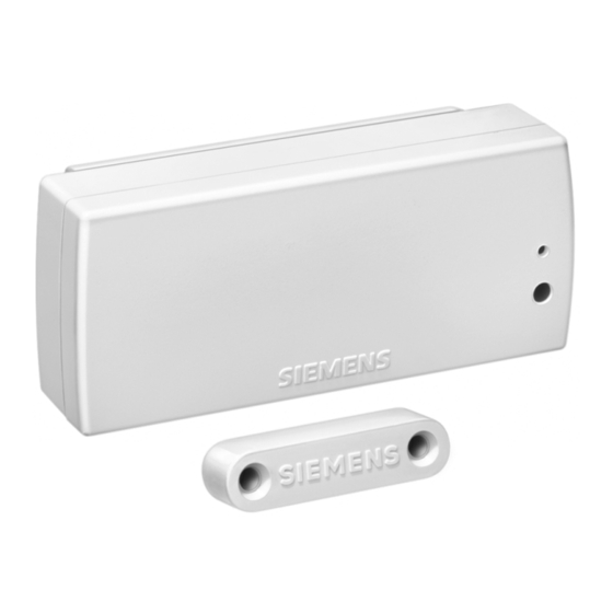
Binary Input wave AP 261
Product and Applications Description
The binary input wave AP 261 (Diagram A) is a surface-
mounted radio-controlled sensor. Besides the integrated
reed contact it is also possible to connect and monitor an
external contact. The difference between the binary input
wave AP 261 and the door/window contact wave AP 260
is that the binary input transmits ON/OFF switching
commands instead of Door/Window Open/Closed mes-
sages as the door/window contact does. With these
switching commands all switchable radio-controlled ac-
tuators can be controlled such as switch inserts sys or
universal dimmer inserts sys in connection with push
buttons wave UP 210 as well as the transmitter actuator
230V wave UP 560. Thus the opening and closing of a
door can be used e.g. for lighting control.
The binary input sends a switching command OFF when
the internal or external contact becomes closed and a
switching command ON when the contacts become
opened. The internal contact is closed if the distance be-
tween the sensor (A3) and the magnet (A4) is < 10 mm.
Diagram A
The binary input is supplied with power from a lithium
battery (1/2 AA 3.6V) which is provided with the device.
This battery is rated so that it is only necessary to replace
it approx. every 5 years, even with up to 50 changes in
the switching state per day. If the battery has to be re-
placed, this is indicated by the LED (A1) flashing every
10 s. The battery must then be replaced within a month.
Siemens AG
Automation and Drives Group
Electrical Installation Technology
P.O. Box 10 09 53, D-93009 Regensburg
The commissioning of the binary input is carried out
without any additional tools via a push button located at
the front of the device (A2).
The binary input wave AP 261 has two different opera-
tion modes:
Normal function
• Transmitting switching commands via radio
• Reporting the battery status every 24 hours
Special function
• Establishing connections with other radio- controlled
components
• Deleting connections with other radio
nents
Operation
Once the binary input wave has been installed and
commissioned, a switching telegram is sent each time
the integrated contact or a connected external contact is
opened and closed. Each switching telegram is sent
twice with an interval of one second in order to increase
the reliability of the transmission. To indicate the sending
of a radio telegram, the LED (A1) lights up briefly.
Technical Specifications
Frequency band
868 MHz (transmission is not susceptible to interference;
frequency band reserved for system and security appli-
cations)
A1
Range of radio control
approx. 100 m (In free field applications)
A2
Power supply
lithium battery 1/2 AA 3.6V (e.g. Sonnenschein, type SL-
750), battery operation time approx. 5 years
A3
Connections
A4
4 plug-in terminals for wire ranges between 0.14 and 0.5
2
mm
, single-core or finely-stranded; for setting whether
an external contact is to be connected as well as for the
connection of an external contact.
Mechanical specifications
• Housing: plastic
• Dimensions (L x W x H): sensor: 87x36x27 mm
• Weight of sensor: approx. 65g (with battery)
• Fire load: approx. 800kJ
• Mounting: fixed with adhesive or screws
wave AP 261, 4 pages
Siemens AG 2005
Subject to change without prior notice
instabus rf
Technical Product Information
January 2005
5WG3 261-3AB11
controlled compo-
-
magnet: 40x10x10 mm
Technical Manual
Update: http://www.siemens.de/gamma
2.20.3.2/1
Advertisement

Related Manuals for Siemens AP261


Summary of Contents for Siemens AP261
- Page 1 10 s. The battery must then be replaced within a month. Siemens AG wave AP 261, 4 pages Technical Manual Automation and Drives Group Siemens AG 2005 Electrical Installation Technology Update: http://www.siemens.de/gamma P.O. Box 10 09 53, D-93009 Regensburg Subject to change without prior notice...
- Page 2 It should be ensured that the • Climatic conditions: EN 50090-2-2 SIEMENS markings on the mounting plate and magnet lie on top of each other as much as possible (Diagram B) • Ambient operating temperature: - 5 ... + 45°C and that the distance (gap) between the mounting plate •...
- Page 3 3 and 4 that only the internal contact is used. Siemens AG wave AP 261, 4 pages Technical Manual Automation and Drives Group Siemens AG 2005 Electrical Installation Technology Update: http://www.siemens.de/gamma P.O. Box 10 09 53, D-93009 Regensburg Subject to change without prior notice 2.20.3.2/3...
- Page 4 (G5). Technical Manual wave AP 261, 4 pages Siemens AG Automation and Drives Group Siemens AG 2005 Update: http://www.siemens.de/gamma Electrical Installation Technology Subject to change without prior notice P.O. Box 10 09 53, D-93009 Regensburg...