Advertisement
Quick Links
Service Box
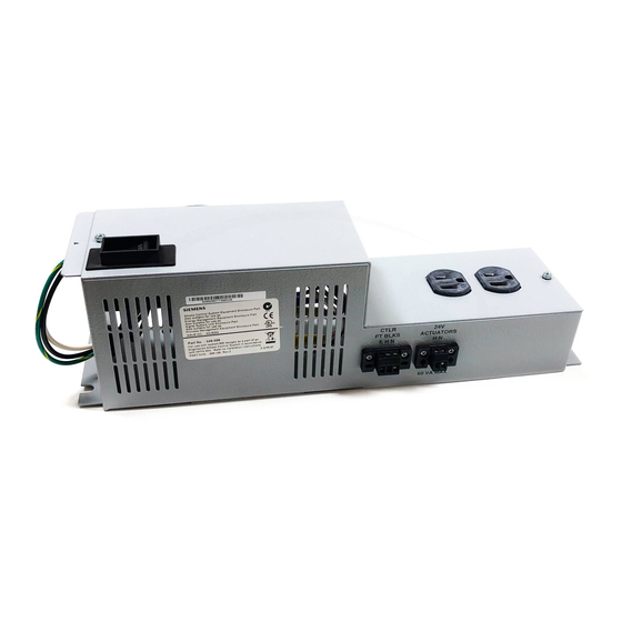
Product Description
The Service Box kit includes all the assembled parts
necessary to install in an enclosure. The kit consists of
a service box, a 115 Vac or 230 Vac to 24 Vac
transformer, a power switch, a 115 Vac or 230 Vac
mounting plate, a service box cover, and a wire cover.
Product Numbers
549-506
Service Box with two 24V connections,
115V
549-507
Service Box with two 24V connections,
230V
Required Tools and Material
•
Medium Phillips screwdriver
•
11/32-inch nutdriver
•
7/16-inch nutdriver
Expected Installation Time
25 Minutes
Warning/Caution Notations
WARNING:
CAUTION:
WARNING:
This installation should only be done by
a qualified electrician.
Item Number 586-135(CA)
Personal injury/loss of life may
occur if a procedure is not
performed as specified.
Equipment damage, or loss of
data may occur if the user
does not follow procedure as
specified.
Installation Instructions
WARNING:
Turn off AC power to the Enclosure at
a circuit breaker panel.
Instructions
NOTE: Where applicable, the numbers in Figures 1, 2,
and 3 correspond to the numbered instructions.
1.
Be sure the AC power to the Enclosure at the
circuit breaker panel is OFF.
2.
Place the service box in the right side of the
enclosure.
3.
Fasten the service box inside the enclosure with
the three locknuts (two on top and one on the
bottom).
4.
Connect the ground wires and fasten the locknut
inside the service box, sandwiching the wires
between washers.
NOTE: For installations requiring CE Compliance,
place an included IEC Ground Symbol
label near the ground wire connection.
5.
Connect the ground wire at the top of the service
box with a locknut.
NOTE: For installations requiring CE Compliance,
place an included IEC Ground Symbol
label near the ground wire connection.
6.
Connect the AC hot and AC neutral (black and
white) wires with wire nuts.
7.
Place the service box cover on the service box
and fasten the three screws.
8.
Fasten the wire cover to the top of the service box.
9.
Restore power to the enclosure at the circuit
breaker panel.
The installation is now complete.
Document No. 586-135
August 1, 2008
Page 1 of 2
Advertisement

Summary of Contents for Siemens 549-506
- Page 1 3 correspond to the numbered instructions. Product Numbers Be sure the AC power to the Enclosure at the circuit breaker panel is OFF. 549-506 Service Box with two 24V connections, 115V Place the service box in the right side of the enclosure.
- Page 2 Information in this publication is based on current specifications. The company reserves the right to make changes in specifications and models as design improvements are introduced. Other product or company names mentioned herein may be the trademarks of their respective owners. © 2008 Siemens Building Technologies, Inc. Your feedback is important to us. If you have Document No.