
Summary of Contents for MINDS-I UAV Mini
- Page 1 CKE-M305-001 Mini MultiRotor nmanned erial ehicle Helpful instructional videos available at: mindsieducation.com...
- Page 3 MINDS-i® PRODUCT SAFETY INFORMATION When safety precautions are followed, your MINDS-i® system will provide years of enjoyment. Use care and good sense at all times when operating this product. Failure to use your system in a safe, sensible manner can result in injury or damage to property. You and you alone must insure that the instructions are carefully followed and all safety precautions are obeyed.
- Page 4 Washington State address, MINDS-i® will calculate the sales tax when the order is processed and call or email the customer with the new amount. All prices, materials, design, color, contents included with a product and product specifications are subject to change without notice.
- Page 5 CONNECTOR ASSEMBLY AND USAGE HELPFUL INSTRUCTIONAL VIDEOS AVAILABLE AT: www.mindsieducation.com 1.5-LOCK 2-LOCK 3-LOCK PANEL-LOCK 2-ROTATE 3-ROTATE...
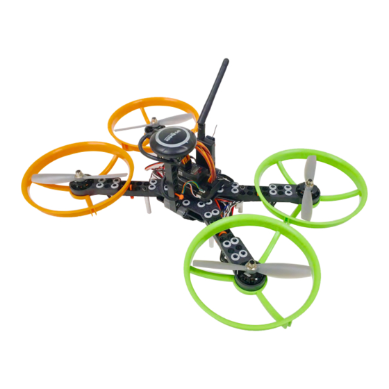
- Page 9 UAV Mini...
- Page 10 CLOCKWISE (CW) 5” DUCT 2205 MOTOR MOUNT M3x8mm SCREW #4 WASHER CLOCKWISE MOTOR AND ESC COUNTERCLOCKWISE (CCW) 5” DUCT 2205 MOTOR MOUNT M3x8mm SCREW #4 WASHER COUNTERCLOCKWISE MOTOR AND ESC...
- Page 11 CLOCKWISE (CW) 5” DUCT 2205 MOTOR MOUNT M3x8mm SCREW #4 WASHER CLOCKWISE MOTOR AND ESC COUNTERCLOCKWISE (CCW) 5” DUCT 2205 MOTOR MOUNT M3x8mm SCREW #4 WASHER COUNTERCLOCKWISE MOTOR AND ESC...
- Page 12 CHOOSE YOUR X TOP PLATE X-15 15-BEAM Diagonal size of 405 mm. Will have a softer flight characteristic. Having the longest arms requires the most thrust to change angle in the air. Being an X frame it will respond with the same movement forward-backward as it will left- right.
-
Page 13: Frame & Size
FRAME & SIZE STRETCH X TOP PLATE 15-BEAM Center to center size of 350 mm x 205 mm. STRETCH-15 Will have a softer flight characteristic. Having the longest arms requires the most thrust to change angle in the air. Being a stretch X frame it will be more responsive when steering left-right than forward- backward, ideal for racing. - Page 14 PANEL-LOCK GREEN FORWARD NOTE: SLOTS SHOULD FACE FRONT TO BACK...
- Page 15 #4-40 x 5/8” SCREW #4 WASHER CLEARANCE THREAD ADAPTER INTERFERENCE THREAD ADAPTER SHROUD STUD 1/4” SILICONE CAP...
- Page 16 WITH THE ESC’S WIRE TIED TO THE ARMS OF THE FRAME, ROUT THE WIRING AS SHOWN BELOW. BE SURE TO NOTE THE POLARITY OF THE ESC’S WHEN CONNECTING TO THE POWER MODULE (RED TO RED AND BLACK TO BLACK). MARK THE MALE END OF THE SERVO EXTENSIONS WITH THE CORRESPONDING ESC/MOTOR NUMBER AND TUCK THE CONNECTION IN- BETWEEN THE FRAME PLATES WITH THE POWER MODULE.
- Page 17 VELCRO STRAP X BOTTOM PLATE STRETCH X BOTTOM PLATE PANEL-LOCK...
- Page 18 FOR USE WITH THE GPS UNIT (NOT INCLUDED IN UAV MINI COMPETITION KIT) 10-BEAM 7-BEAM 3-BEAM TRANSITION 3-LOCK 2-LOCK PANEL-LOCK...
- Page 19 PANEL-LOCK ATTACH THE PROVIDED VELCRO (LOOP SIDE) TO THE PLACES SHOWN IN BLUE. THEY WILL BE USED TO SECURE THE ELECTRONICS. VELCRO LOOP...
- Page 20 ATTACH THE PROVIDED VELCRO (LOOP SIDE) TO THE PLACE SHOWN IN BLUE. IT WILL BE USED TO SECURE THE RADIO RECEIVER. REFER TO THESE IMAGES AND THE WIRING DIAGRAM ON THE NEXT PAGE TO PROPERLY ATTACH AND CONNECT THE ELECTRONICS.
- Page 22 UAV MINI COMPETITION KIT THE FOLLOWING IS FOR THE UAV MINI COMPETITION KIT ONLY. WITH THE FLIGHT CONTROLLER ORIENTATED AS SHOWN ABOVE. INSERT THE INCLUDED JUMPER INTO THE BOTTOM PAIR OF PINS AS INDICATED. FOR MODELS NOT USING THE GPS/ COMPASS MODULE THIS ALLOWS THE USE OF...
-
Page 23: Dashboard Setup
Dashboard Setup Warning! Before continuing further, please ensure that you have NOT mounted the propellers on the MultiRotor. If you would prefer to use the Mission Planner software for autonomous flight, instructions can be found here: http://mindsieducation.com/files/pdf/mission-planner.pdf... - Page 25 Flight Systems Setup Checklist #1 Calibrate Sensors #2 Calibrate ESC’s #3 Upload UAV Mini Code #4 PID Test Rack #5 Connecting to the Dashboard...
-
Page 26: Step #1 Calibrate Sensors
Step #1 Calibrate Sensors: Open Arduino> click open> libraries> MINDS-i-Drone> CalibrateSensors.ino. Make sure you have the correct board (MEGA 2560) and port selected (whatever port says MEGA 2560). A: Click the upload button. B: Once the upload is complete open the serial monitor. - Page 27 With the serial monitor open follow the instructions as prompted. Move the MultiRotor and hold on each face until the column displays an “ok”. Once all of the columns say “ok” you will type a “y” into the top bar and press enter. You have successfully calibrated the accelerometer and compass.
- Page 28 Step #2 Calibrate ESC’s: Open Arduino> click open> libraries> MINDS-i-Drone> CalibrateEMaxESCs.ino. Make sure you have the correct board (MEGA 2560) and port selected (whatever port says MEGA 2560). Click the upload button. Once the upload is complete disconnect the MultiRotor from the computer.
- Page 29 Step #3 Upload Quadcopter Code: Open Arduino> click open> libraries> MINDS-i-Drone> quadcopter.ino. Make sure you have the correct board (MEGA 2560) and port selected (whatever port says MEGA 2560). Click the upload button. Once the upload is complete disconnect the MultoRotor from the computer.
- Page 30 Step #4 PID Test Rack: Set up your PID Test Rack as shown below. Mount the MultiRotor to the rack using the provided parachute cord. Loop the cord through the open hole in the transitions on the antenna mount and the GPS stand.
- Page 31 While one student holds the MultiRotor centered feed one side of the cord through the hole in stand an loop it through a MINDS-i Beam as shown. Tie the chord off and repeat on the other side. Make sure to pull the chord tight, a slight bowing of the test stand is desirable.
- Page 32 56700 baud, but after configuration they will connect at 9600 baud • Make the changes you want, or press “Import defaults” to automatically configure it for use with MINDS-i drones • Press “Save Changes”, disconnect, and power cycle the telemetry radio •...
-
Page 33: Transmitter And Receiver Binding
Servo Reversing (DXe) To enable servo reversing, hold the left and right gimbal sticks in the upper-inside position as shown while powering on the transmitter. Left Gimbal Right Gimbal After the Transmitter is powered on, release the sticks and return to center. Use the right gimbal to select the channel or reverse the selected channel. - Page 35 M I N D S - i D a s h b o a r d...
- Page 37 Dashboard Features & Functions Waypoint Panel Connection Panel Data Panel Terminal...
- Page 38 Waypoint Panel: Configuration: Opens a pop up window with the Telemetry Radio Configuration tool. View Button: This button switches the map between satellite and elevation views. Navigation: Zoom in and out. Telemetry: Opens a window allowing you to select the information that will be recorded in the log as well as all of the adjustable settings for the vehicle.
- Page 39 Configuration: Toggle ground/air mode: Switches between ground and air mode. Driver Installer: Launches the installer for the radio driver. Refresh: Refreshes the serial port list. Com Port List: Shows the open com ports. Baud Rate: Used to set the communication speed. Connect: Connects to the telemetry radio to adjust the settings.
- Page 40 Telemetry: Data Log Window: The data log opens in a new window. ID Column: Lists the names of the preset data to be logged as well as the open slots. Value Column: Includes the value for each row of data. Data Log Interval: Period of time between saving data.
- Page 41 Graph: Configure: Opens Graph Configuration. Anti Alias: Used to smooth jagged edges on curved lines and diagonals. Scaling: Adjusts the scale of the graph. Data Name Check Box: User input for the data to be graphed. Color Settings: User selected color for each row of data selected. Select the check box in the row of the data desired to be graphed then select the color you would like the line to be on the graph, repeat for each row of data.
-
Page 42: Event Log
Event Log: Event Log: Lists all attempts of communication between the vehicle and the Dashboard software (successful or not). -
Page 43: Data Panel
Data Panel: Data from the robot will populate this panel when connected. A lack of data when connected could indicate a failing connection to the robot, possibly from distance or obstacles blocking the signal. Altitude (Above Ground), Altitude (Sea Level), Speed (MPH), Battery Voltage (Vcc). Vehicle Direction (compass heading) Vehicle Pitch &... -
Page 44: Connection Panel
Connection Panel: The refresh button will repopulate the drop down menu with the currently available serial ports To connect, select the appropriate serial port in the drop down and press connect. When a connection has been established, the “Connect” button will change to say “Disconnect”... -
Page 45: Map View
Map View: • The rover will automatically be placed on the map where the GPS indicates it is located • Click and drag on the map to pan your view • Scroll on the map to zoom • Click on any empty part of the map to add a waypoint to the end of the current path •... -
Page 46: Radio Configuration
Connecting to your Drone First time only: • Follow the setup instructions in the MINDS-i Drone Library repository for your drone • Make sure appropriate drivers are available for your telemetry radios • If you are running windows, a driver installation button is available in the configuration menu. -
Page 47: Artificial Horizon
Switching Between Ground and Air Mode To switch the dashboard between ground drone and air drone mode, Open the configuration window, press “Toggle ground/air mode”, and then restart the dashboard Artificial Horizon When in air mode, the artificial horizon widget can be clicked on to open a full size window with altitude and heading overlaid on the right and top edge respectively. - Page 48 ATTACH THE PROVIDED VELCRO (LOOP SIDE) TO THE PLACES SHOWN IN BLUE. THEY WILL BE USED TO SECURE THE BATTERY. VELCRO LOOP ATTACH THE MATING VELCRO (HOOK SIDE) TO THE BATTERY. THE BATTERY SHOULD BE CENTERED ON THE FRAME THEN STRAPPED IN.
- Page 49 USING THE SPANNER WRENCH TO HOLD THE MOTORS WHILE TIGHTENING THE NYLON LOCK NUTS DOWN. PAY CAREFUL ATTENTION TO THE DIRECTION OF ROTATION FOR THE PROPELLERS. 5045 BULLNOSE PROPELLER CCW 5045R BULLNOSE PROPELLER CW 8mm FLANGE NUT...
- Page 50 On Rack Pre-Flight Check • With UAV in the test rack, point the front facing away from you. • Turn the transmitter on. • Plug in the LiPo battery. • Wait for the UAV to steady itself (it will not arm if it is swinging at all). •...
- Page 51 Preflight 1. Always wear safety glasses. 2. NEVER operate without the safety 3. Left stick fully down ducts. 4. Set flight mode 5. Power on transmitter 6. Connect charged battery 7. Place at Launch point 8. Check for solid blue LED GPS Lock, 9.
- Page 52 For the latest from MINDS-i visit: mindsieducation.com For technical questions with programming email: code@mymindsi.com Patents US 7,517,270; US 7,410,225; US 7,736,211; US 7,841,923; MX 288,350; Additional Patents Pending. Trademarks 3,420,137 and 3,487,694 Copyright © 2012 MINDS-i Inc. All rights reserved.
Need help?
Do you have a question about the UAV Mini and is the answer not in the manual?
Questions and answers