
Related Manuals for Nikon DS-2MBW


Summary of Contents for Nikon DS-2MBW
- Page 1 M306E 05.04.CF.7 (1/2) DS Camera Control Unit DS-L1 DS Camera Head DS-5M/DS-2Mv/DS-2MBW DS Cooled Camera Head DS-5Mc/DS-2MBWc < Instructions > (Ver. 3.0)
- Page 3 Thank you for purchasing the Nikon products. This instruction manual has been prepared for users of the DS Camera Control Unit DS-L1, DS Camera Head DS-5M/DS-2Mv/DS-2MBW, and DS Cooled Camera Head DS-5Mc/DS-2MBWc. To ensure correct use, please read this manual carefully before using these products.
-
Page 4: Power Cord
Never attempt to disassemble any part of the equipment unless instructed to do so in this manual. If you notice any problems with the equipment, turn off the power and contact your nearest Nikon representative. -
Page 5: Installation Environment
1. Installation environment • Do not use this equipment in locations subject to high temperatures, high humidity, vibration, or excessive amounts of dust. Doing so may result in fire or malfunction. • When used for an extended period of time, the DS-L1 may become hot. Do not place the DS-L1 on a surface that cannot withstand heat (such as vinyl or plastic). -
Page 6: Table Of Contents
CONTENTS Before Use ... 1 1 Types of DS Camera Head ... 1 2 Components ... 2 Peripheral Equipment ... 3 Names of Parts and Their Functions ... 6 1 DS Camera Control Unit DS-L1... 6 2 DS Camera Head... 9 3 DS Remote Controller DS-RC (Optional) ... - Page 7 2.2 Using a CF Card...58 2.2.1 Saving an Image to a CF Card—REC Menu ...58 2.2.2 Reproducing Images from a CF Card—VIEW Menu...61 2.2.3 Using Dual-Window Display to Compare with the Reference Image ...62 2.3 Outputting Images Directly to a Printer ...63 2.3.1 Printing an Image...63 2.3.2 Various Print Related Settings ...63 3 Measuring Two-point Distance or Entering Information—TOOL Menu...
- Page 8 4.6.3(1) Using the CAPTURE Button to Save Image Files ... 112 4.6.3(2) Using the CAM Menu to Save Image Files ... 113 5 Using the DS-L1 when Connected to a PC by a USB Cable ... 115 5.1 Recommended Operating Environment ... 115 5.2 Connecting the DS-L1 and a PC ...
- Page 9 CONTENTS 3 DS Remote Controller DS-RC ... 169 4 DS AC adapter ... 170 5 Overall Specifications... 170 - vii -...
-
Page 11: Before Use
Indication of DS camera head model name In this manual, the product names, "DS Camera Head DS-5M," "DS Camera Head DS-2Mv," "DS Camera Head DS-2MBW," "DS Cooled Camera Head DS-5Mc," and "DS Cooled Camera Head DS-2MBWc" are abbreviated "DS-5M," "DS-2Mv," "DS-2MBW,"... -
Page 12: Components
Components Check to see that all the items listed below are provided in the package. If any items are missing, contact your nearest Nikon representative immediately. DS Camera Control Unit DS-L1 Instruction manual DS AC adapter Power cord I Before Use... -
Page 13: Peripheral Equipment
TOOL functions such as length measurement or the pen drawing function, or histograms). The mouse can also be used for various menu settings and operations. Be sure to use a USB mouse recommended by Nikon. (Not every USB mouse is compatible with the DS-L1.) -
Page 14: Usb Printer
• • The image circle is 2/3" for the DS-5M and DS-5Mc and 1/1.8" for the DS-2Mv, DS-2MBW, and DS-2MBWc. Use a lens for 2/3" or larger (e.g., 1”). When using diaphragm settings brighter than F2.8, you may observe slight light falloff •... -
Page 15: Personal Computer (Pc)
(11) Nikon 80i/90i Microscope / LV150A Industrial Microscope If you have a Nikon 80i/90i microscopes equipped with a digital imaging head, you can purchase a license to control the microscope or display its status using the menus on DS-L1. To connect your Nikon 80i/90i microscope to the DS-L1, use the USB cable provided with the microscope. -
Page 16: Names Of Parts And Their Functions
Names of Parts and Their Functions DS Camera Control Unit DS-L1 Front of the DS-L1 POWER switch This is a push switch. Press it to turn on the power. Press again to release it and turn off the power. When the power is on, the LED indicator lights and remains on. - Page 17 Or connect a PictBridge-supporting printer to perform the direct print. USB host port Use this port to connect a USB mouse, USB keyboard, USB printer (CP900D), or Nikon microscope. Network Tx indicator Lights when sending data to a LAN. Network Rx indicator Lights when receiving data from a LAN.
- Page 18 III Names of Parts and Their Functions Rear of the DS-L1 RGB connector Use this connector to connect an external monitor. External interface output Connect a stroboscope or other external device here. This output generates a synchronizing signal when capturing an image, enabling the strobe light to be turned on synchronously.
-
Page 19: Ds Camera Head
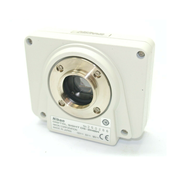
III Names of Parts and Their Functions DS Camera Head C mount cap Protects the C mount from dust. DS Remote Controller DS-RC (Optional) FREEZE button Freezes the current image as a still picture. To release the frozen image, press the button again. -
Page 20: Connecting And Installing The Equipment
Connecting and Installing the Equipment Connection Diagrams Schematic diagram DS-L1 PC or a PictBridge- USB cable supporting printer USB equipment, mouse, keyboard, printer, and Nikon misroscope LAN cable CF card DS AC adapter DS-RC DS camera head - 10 -... - Page 21 Connectors · DS-L1 Left side PC or a PictBridge- supporting USB mouse printer USB keyboard Printer Microscope DS AC adapter · DS-L1 Rear IV Connecting and Installing the Equipment 1 Connection Diagrams USB cable ← USB equipment LAN cable LAN ← RGB cable Remote cable ↓...
-
Page 22: Installing The Ds-L1
IV Connecting and Installing the Equipment Installing the DS-L1 When installing the DS-L1 on a flat surface such as a desktop by using the stand arm Extract the stand arm from the DS-L1 and place it at an angle of 5 to 10 degrees, as shown below. -
Page 23: Connection Methods
You can also attach a relay lens. We recommend the x0.7 relay lens for the DS-5M and DS-5Mc. We recommend the x0.55 relay lens for the DS-2Mv, DS-2MBW, and DS-2MBWc. When you have mounted the DS camera head on a microscope, be sure to read "Chapter V Microscope Adjustment"... -
Page 24: Connecting To A Network
Be sure to turn off the power for the DS-L1 before making any connections. When using a USB mouse, USB keyboard, USB printer (Mitsubishi CP900D), or Nikon 80i/90i microscope independently, connect the device directly to the USB-H connector on the DS-L1. - Page 25 IV Connecting and Installing the Equipment Connecting to a PC without going through a LAN Left side of the DS-L1 (7) Connecting External I/O Devices Be sure to turn off the power to the DS-L1 and any equipment to be connected before making connections.
-
Page 26: Connecting To A Power Supply
This product belongs to electric shock protection class I and must be connected to a power outlet with a protective ground terminal. If you misplace or damage the DS AC adapter power cord, please contact your nearest Nikon representative. 3 Connection Methods E≤24V... -
Page 27: Microscope Adjustment
(GIF) or a monochrome interference filter (IF). We recommend simultaneous use of an NCB filter and a green interference filter (GIF) for the DS-2MBW and DS-2MBWc. Some microscopes may require a heat-wave absorption filter. Terms... -
Page 28: Adjusting The Focus
(2) Adjusting the Field Diaphragm Adjust the field diaphragm so that it circumscribes the viewfield. The field diaphragm has a significant impact on contrast, especially for fluorescent specimens against dark backgrounds. Make sure you adjust the field diaphragm correctly. For details on adjustment, refer to your microscope’s instruction manual. -
Page 29: Adjusting The Exposure Time
(6) Adjusting the Exposure Time Use an ND filter to adjust the illumination for the microscope to a level that yields a suitable exposure time (generally 1/15 to 1/250 s). You can also adjust the camera sensitivity. Terms What is an ND filter? An ND filter is a filter that affects only the amount of light passed, not the color balance of the light. -
Page 30: Basic Operations
2-megapixel CCD / color / non-cooled 2-megapixel CCD / monochrome / non-cooled 2-megapixel CCD / monochrome / cooled -> DS-5M and DS-5Mc -> DS-2Mv, DS-2MBW, and DS-2MBWc -> DS-5Mc and DS-2MBWc -> DS-5M, DS-2Mv, and DS-2MBW -> DS-2MBW and DS-2MBWc... -
Page 31: Preparations Before Photographing
Preparations Before Photographing Using Various Input Devices 1.1.1 Using the DS-L1 Panel Switches ZOOM button MENU button (menu/enter button) Pressing the MENU button brings up the CAM Easy menu. While the menu is displayed, use this button as the ENTER button to confirm your selection. VI Basic Operations 1 Preparations Before Photographing FREEZE button... -
Page 32: Cursor Buttons
.SETUP. Cursor buttons Use these buttons to select an icon in a menu or to increment or decrement a set value. For an icon to increment or decrement a value such as the Gain icon on the CAM • menu Position the cursor over the icon and press the MENU button to select the icon. -
Page 33: Using A Mouse
1.1.3 Using a Mouse You can use a USB mouse with the DS-L1. Be sure to use a recommended mouse. Not every USB mouse is compatible with the DS-L1. While most normal operations involve left-clicking the mouse, some may require right-clicking. For icons to set a value or select a mode, left- or right-clicking the mouse button allows you to increment or decrement a value or select items in the forward or reverse direction. -
Page 34: Using A Keyboard
.SETUP. 1.1.4 Using a Keyboard You can use a USB keyboard with the DS-L1. For frequent text or character entry, you'll find using a keyboard most convenient. Be sure to use a recommended type of keyboard. Not all USB keyboards are compatible with the DS-L1. Alphanumeric characters in upper- or lowercase can be used with the DS-L1. -
Page 35: Notes On Using A Cf Card
Notes on Using a CF Card Images can be saved to or reproduced from a CF card. Pay attention to the following when using a CF card: Use a Type-I or Type II-compliant CF card or microdrive. • Carefully read the user's manual provided with your CF card before using the card. •... -
Page 36: Menu Configuration And Method Of Displaying A Menu
.SETUP. Menu Configuration and Method of Displaying a Menu 1.3.1 Menu Configuration The menus available with the DS-L1 are listed below. Shortcut menus CAM (Easy / Advn. / Reg.) VIEW TOOL SETUP Power ON Settings Network Settings File Settings Additional Settings Shortcut MIC INFO Common icons on CAM, VIEW, REC, TOOL and MIC menus... -
Page 37: Method Of Displaying A Menu
1.3.2 Method of Displaying a Menu Follow the procedure described below to show or hide a menu or to switch between menus. Using the MENU button on the main unit front panel Press the MENU button to display the CAM Easy menu. To change menus, select your desired tag with one of the cursor buttons and press the MENU button (which functions as the enter button) to confirm. -
Page 38: Initial Settings
.SETUP. Initial Settings When using the DS-L1 for the first time after purchasing, you must make the following environment settings before photographing any image. (1) Date and power-save settings Set the unit clock and power-save timer. (2) Image file-save related settings Set an image file format and compression rate, the folder and file names in which to save the file, and the source (photographing mode). - Page 39 VI Basic Operations 1 Preparations Before Photographing Date:, Time: Enter a date and time. NOTE: If the DS-L1 remains turned off for extended periods, its internal timer may slow down or stop. When the DS-L1 starts up, it displays the date and time set in its timer (flashes for about 8 seconds).
-
Page 40: Image File Settings-File Settings
.SETUP. 1.4.2 Image File Settings—File Settings Display a menu and select the [SETUP] tag on it to enter the SETUP menu. Select from the SETUP menu to display the File Settings screen shown below. When you have finished setting each item, press press Default to restore data to default values. - Page 41 You can write up to 100 characters to a log when saving an image to a card or server, or up to 32 characters when outputting to a printer. Photographed data (including Nikon 80i/90i microscope data during photography) is also contained in a log.
- Page 42 .SETUP. Fine: Draft: NOTE: You can also select the file format when saving an image from the REC menu. The following table gives the resulting file sizes for various image file settings. Since actual file sizes of JPEG images can vary widely from image to image, the JPEG values given here are intended to serve only as a guide.
- Page 43 1 Preparations Before Photographing Display mode (CAM menu) 3.75 cameras 1.3Mi 6.75 1.3Mp C.Scan 2Mfull cameras 800*6 800*5 C.Scan Features of display modes The various display modes offer different advantages, as described below. 5M cameras (Cameras suitable for high-resolution applications) An image area of 2560*1920 pixels is reduced for display at the monitor resolution (1280*960/SXGA or 1024*768/XGA).
- Page 44 .SETUP. 2M cameras (Cameras suitable for applications requiring a high frame rate and good motion performance) 2Mfull 800*6 800*5 C.Scan VI Basic Operations 1 Preparations Before Photographing This display mode is useful when good performance with moving subjects is required. Regardless of the source setting, the CCD mode switches to match the shutter speed, resulting in delays during image acquisition.
- Page 45 1 Preparations Before Photographing Auto change CCD mode Select "Auto change CCD mode" for automatic adjustment of the CCD mode to match the camera shutter speed when the source is set to maximum resolution ("s5M" for 5M cameras or "s2M" for 2M cameras). This mode lets you observe bright subjects at high speed or dark subjects at high resolution without manually adjusting the display mode.
-
Page 46: Startup Condition Settings-Power On Settings
.SETUP. 1.4.3 Startup Condition Settings—Power On Settings Display a menu and select the [SETUP] tag on it to enter the SETUP menu. Select Power On Settings below. The following items can be set in the Power On Settings screen. When you have finished setting each item, press press Default to restore data to default values. -
Page 47: Adjusting Monitor Output For An External Monitor
SXGA/XGA,LCD Select a monitor output state from those listed below. XGA (LCD ON) LCD Color: SXGA (LCD OFF): XGA (LCD OFF): XGA (LCD ON): LCD Back Light Adjust the brightness of the internal monitor. Display(VGA, LCD) Color Adjustment Adjust the color balance of the internal monitor. Use R_GAIN, G_GAIN and B_GAIN to adjust each of the R, G, and B colors. -
Page 48: Settings For Direct Print
Settings for Direct Print Before images can be output directly to a printer, you must enter a direct print license first. NOTE: Contact your nearest Nikon representative for information on how to purchase a direct print license. Follow the procedure described below to set a direct print license. -
Page 49: Settings For Connecting A Microscope
* PictBridge Standard PictBridge is the standard which allows to print the images photographed by a digital camera directly, without a PC, and the interconnection between a digital camera and a printer is supported by manufacturers of respective products. For details, refer to the PictBridge official website: http://www.cipa.jp/pictbridge/ 1.4.6... -
Page 50: Photographing Images
.CAMERA. Photographing Images Adjusting Camera Operation and Exposure for Better Picture Quality—CAM Menu The CAM menu is displayed immediately after you display any menu or when you select the CAM tag. The CAM menu has the following functions for setting photographing conditions. Four display modes are provided that are classified by resolution, sensitivity, live speed, •... -
Page 51: Correct Exposure
Photographing procedure To photograph an image from the Easy menu, follow the procedure described below. (1) Choose scene mode and custom mode. Choose these modes according to the subject and the method of observation. (2) Adjust the white balance. Prepare an evenly white subject and adjust the white balance with (3) Adjust the focus. - Page 52 .CAMERA. (1) Choosing scene mode and custom mode Choose a scene mode that suits the subject and the method of observation. Scene mode To change the scene mode for industrial or biological specimens, use Cam OSD on Power On Settings as selected from the SETUP menu. •...
-
Page 53: Adjusting The White Balance
Custom modes Custom mode is the mode in which the set values for individual subjects and objectives and those of scene modes are saved. Pressing one of the buttons up the saved content of the selected custom mode. You also can confirm the information in the Info box. -
Page 54: Saving The Image
.CAMERA. (6) Saving the image (Capt. button) or the CAPTURE button on the DS-L1 to save the image. (Capt. button) and the CAPTURE button on the DS-L1 are functionally the same. The image is saved to the destination that has been assigned to the button. You can also use these buttons to print the image. - Page 55 To get out of the DF/FL scene mode, select another scene mode or the custom mode. NOTE: When connecting DS-L1 with the Nikon 80i microscope equipped with DIH-E or Nikon 90i microscope via USB, the shutter for the episcopic illumination will automatically open or close, corresponding to the DF/DL scene mode operation.
-
Page 56: Fine Adjustment Before Photographing-Advn. Menu
.CAMERA. 2.1.3 Fine Adjustment before Photographing—Advn. Menu Select the [Advn.] tab on the CAM menu, and the Advn. menu will be displayed. In the Advn. menu you can make various settings of the camera individually to obtain an optimum combination of settings for the intended subject. Configuration of the Advn. - Page 57 Monochrome cameras (No color settings are displayed.) Photographing procedure Follow the procedure described below for general photography. By referring to the procedure below, find a method that is most suitable for the purpose of observation or the intended subject as you photograph an image. (1) Choose display mode.
- Page 58 .CAMERA. (1) Choosing display mode Display mode here refers to one that is used to determine how an image is displayed on the screen. Feeling or features of camera operation vary with a combination of display mode and the source you use during photographing.
- Page 59 VI Basic Operations 2 Photographing Images If fluctuations in exposure caused by movement of the subject presents a problem, use • AE_L to temporarily hold the exposure value. During that time, red. • Recommended example: General photography of a relatively bright subject S_AE: Choose “S_AE”...
- Page 60 .CAMERA. NOTE: Adjusting the focus of a dark subject can also be performed by pressing the increased to adjust the exposure automatically so that the exposure time will not be too long. Then, the live image is displayed while keeping the exposure status.
- Page 61 To suppress unevenness in bright parts while photographing an image with clearly • distinguishable dark and bright areas → TONE6 Recommended example: Metal tissue or ceramics and other materials, photographing documents with a lens, etc. To enhance contrast for easy recognition → TONE7 •...
-
Page 62: Adjusting The Picture Quality
.CAMERA. Next, adjust the exposure. It would be ideal if the amount of incident light can be adjusted in such a way that the shutter speed falls within a range of about 1/7.5 to 1/250 seconds. To adjust the amount of incident light, adjust the luminous energy of the light source or the iris diaphragm or use an ND filter. -
Page 63: Shading Correction
Watch the image while you make adjustments. Also, be careful not to forget to reverse previous settings. Effects COLOR / B&W / NEGA / BlueB / Sepia You can choose color effects on an image from the following five choices: •... - Page 64 .CAMERA. If a red or sky blue bar is displayed during automatic exposure (AE), you are outside the exposure controllable range. Therefore, adjust the amount of incident light by adjusting the luminous energy of the light source or the iris diaphragm or by using an ND filter. Confirm the effective level of the photographed image from image distribution (with a histogram).
- Page 65 NOTE: The CAPTURE button can be assigned any desired function by the Capture Function on Additional Settings, whether it be saving to a CF card, saving to an FTP server, or outputting directly to a printer. Refer to “1.4.1 Date and Power-save Settings-Additional Settings”...
-
Page 66: Special Photography On Advn. Menu -Fluorescent Photographing Or Dark Subject Photographing
.CAMERA. 2.1.4 Special Photography on Advn. Menu —Fluorescent Photographing or Dark Subject Photographing The following settings are recommended for fluorescent photography or dark subject photography. Settings on the CAM Advn. menu Displayed only when the cooled camera is connected. Cooled Example screen for DS-5MC Display shown at end of exposure (only when the cooled camera is... -
Page 67: Special Photography On Advn. Menu - Stroboscope Photographing
Other settings required In File Settings of the SETUP menu, set the source to “s5M” or “s2M” (high picture • quality). In Additional Settings of the SETUP menu, set External Out to “OFF” (without shutter • delay). Check the screen for any abnormality. If no problems are found, save the image. NOTE: If you are photographing a dark subject that requires a long exposure time, use the camera head in a cool place to allow for its temperature to decrease. -
Page 68: Using A Cf Card
.CAMERA. Using a CF Card The DS-L1 allows you to save a photographed image to a CF card. You also can reproduce a saved image on the screen from the CF card. 2.2.1 Saving an Image to a CF Card—REC Menu Select the [REC] tag at the top of the CAM menu screen. - Page 69 VI Basic Operations 2 Photographing Images In the REC menu, you can specify the photographing source, file format, image size, and compression rate when saving an image. • Choose the source, either “s5M” for 5M cameras or “s2M” for 2M cameras to obtain high picture quality.
-
Page 70: Interval Photography
.CAMERA. Saving an image To save an image to a CF card from the REC menu, follow the procedure described below. Choose “1shot” if you want to save only one image sheet. Choose “Continue” to save multiple image sheets at given intervals. Change the destination or file name to or in which to save, as necessary. -
Page 71: Reproducing Images From A Cf Card-View Menu
2.2.2 Reproducing Images from a CF Card—VIEW Menu Display a menu and select the [VIEW] tag on it to enter the VIEW menu. In the VIEW menu, you can reproduce images on the screen from a CF card. You also can delete image files from the CF card or display a thumbnail. -
Page 72: Using Dual-Window Display To Compare With The Reference Image
.CAMERA. Using the formatting function If you insert a CF card formatted in NTFS, i.e., formats not supported by the DS-L1, the following message will be displayed on the VIEW menu. “Error !! Unacceptable CF Card Format (FAT16) ? Format Press the Format NOTE: CF cards formatted in other than NTFS may not be correctly formatted in... -
Page 73: Outputting Images Directly To A Printer
Outputting Images Directly to a Printer 2.3.1 Printing an Image When operating from a shortcut menu or the REC menu, use the print icon to print. When selecting CP900D printer or a PictBridge-supporting printer in the Additional Settings screen of the SETUP menu window, a print icon either When operating from the main unit panel switch or the DS Remote Controller DS-CR, you must choose Print for Capture Function in Additional Settings of the SETUP menu before you can print. - Page 74 .CAMERA. Selecting a source Use File Settings of the SETUP menu to select a source. Choose the “s5M” for 5M cameras or “s2M” for 2M cameras source to obtain satisfactory picture quality. The features of each source will be the same as when saving an image. Refer to “1.4.2 Image File Settings-File Settings”...
-
Page 75: Measuring Two-Point Distance Or Entering Information-Tool Menu
If the microscope connected to your system is the Nikon 80i/90i microscope with digital • imaging head, the content drawn with the TOOL menu displayed on the screen (pen, count... - Page 76 .TOOL. 3 Measuring Two-point Distance or Entering Information—TOOL Menu Configuration of the TOOL menu VI Basic Operations Clear All Erases overlay information Overlay ON/OFF Displays or hides overlay Pen function Marker Count marker function Text Text input function Measurement functions Calib.
-
Page 77: What Is An Overlay
3 Measuring Two-point Distance or Entering Information—TOOL Menu What is an Overlay? An overlay is something like a transparent sheet that is placed on top of a photographed image. Text, count markers, pen drawings, measurement lines, or superimposed images can be written on the overlay. -
Page 78: Entering A Comment On The Image
.TOOL. 3 Measuring Two-point Distance or Entering Information—TOOL Menu Entering a Comment on the Image You can enter a comment on the overlay of an image by using the pen drawing, count marking, or text function. An overlay can be placed on top of a live image. If you do not want the image and a comment to be mismatched, use the freeze button to freeze the image before entering a comment. -
Page 79: Using The Count Marker (To Count The Number Of Points)
3 Measuring Two-point Distance or Entering Information—TOOL Menu 3.3.2 Using the Count Marker (to Count the Number of Points) The count marker is a convenient function because it displays numbers in the order in which markers have been attached. Attach a marker to each point on the image, and you can count the number of points easily. -
Page 80: Entering Textual Comments
.TOOL. 3 Measuring Two-point Distance or Entering Information—TOOL Menu 3.3.3 Entering Textual Comments The text function allows you to enter a textual comment in the image. NOTE: Although text can be entered from a keyboard, you need a mouse to perform other operations. -
Page 81: Measuring On The Screen
Calib. <When using a subject of known length> NOTE: If the microscope connected to your system is the Nikon 80i/90i microscope, set the magnification of the digital imaging head optical zoom to x1.0 before calibrating. Select the number in which you want to save the calibration value (from s7 ). - Page 82 Drag the mouse pointer over one of numbers information for that number will be displayed in the Info area for your confirmation. NOTE: If the microscope connected to your system is the Nikon 80i/90i microscope with motorized or intelligent nosepiece, note that each calibration value call number is linked to the hole number of the nosepiece.
-
Page 83: Calling The Calibration Value
Drag the mouse pointer over one of the numbers information for that number will be displayed in the Info area for your confirmation. NOTE: If the microscope connected to your system is the Nikon 80i/90i microscope with motorized or intelligent nosepiece, note that each calibration value call number is linked to the hole number of the nosepiece. - Page 84 "mil," and an "E" is indicated, representing inch conversion. If the microscope connected to your system is the Nikon 80i/90i microscope with motorized or intelligent nosepiece, note that each calibration value call number is linked to the hole number of the nosepiece. This means you...
-
Page 85: Measuring Perpendicular Distance
"mil," and an "E" is indicated, representing inch conversion. If the microscope connected to your system is the Nikon 80i/90i microscope with motorized or intelligent nosepiece, note that each calibration value call number is linked to the hole number of the nosepiece. This means you... -
Page 86: Measuring Angles
.TOOL. 3 Measuring Two-point Distance or Entering Information—TOOL Menu 3.4.5 Measuring angles You can measure an angle between two lines on the screen and save the measurement line (lines and angle) for this measurement as part of the overlay for the image. Press Measure Press a color icon (red, blue, green, black, white, or yellow) to set the color of the... -
Page 87: Measuring Circles
"mil," and an "E" is indicated, representing inch conversion. If the microscope connected to your system is the Nikon 80i/90i microscope with motorized or intelligent nosepiece, note that each calibration value call number is linked to the hole number of the nosepiece. This means you... -
Page 88: Adjusting The Subject Position And Comparing Sizes
.TOOL. 3 Measuring Two-point Distance or Entering Information—TOOL Menu Adjusting the Subject Position and Comparing Sizes 3.5.1 Using Crosshairs to Adjust the Subject Position You can display crosshairs on the screen and use it to adjust the center or the horizontal or vertical position of the subject. - Page 89 3 Measuring Two-point Distance or Entering Information—TOOL Menu “Center Cross” is an option that allows you to fill the center part of the crosshairs. Select the “Yes” check box to fill the center part of the crosshairs. If you select the “No” check box, the center part of the crosshairs will not be filled.
-
Page 90: Using A Scale To Measure The Subject Size
If you change the objective while using this function, and if the microscope connected to your system is the Nikon 80i/90i microscope using a motorized nosepiece or intelligent nosepiece, the screen display will change accordingly. -
Page 91: Using Xy Scales To Measure The Dimensions Of The Subject
If you change the objective while using this function, and if the microscope connected to your system is the Nikon 80i/90i microscope using a motorized nosepiece or intelligent nosepiece, the screen display will change accordingly. -
Page 92: Creating A Translucent Image And Comparing It To A Live Image
.TOOL. 3 Measuring Two-point Distance or Entering Information—TOOL Menu 3.5.4 Creating a Translucent Image and Comparing It to a Live Image You can create a translucent image from the displayed image on the screen and view it while being laid on top of the live image for comparison. This function may be used to create a translucent scale or inspect registration of shapes. -
Page 93: Measuring Vertical And Horizontal Distances
3 Measuring Two-point Distance or Entering Information—TOOL Menu 3.5.5 Measuring vertical and horizontal distances You can measure the horizontal distance (on the x-axis) and vertical distance (on the y-axis) between two cross hairs you display on the screen. Right-click on Cross Select the C.Msr. -
Page 94: Using The Ds-L1 Via A Network
.NETWORK. Using the DS-L1 via a Network Typical Method of Use You can connect the DS-L1 and a PC in a network and operate the DS-L1 from the PC or exchange image files between the DS-L1 and the PC. There are three methods for operating the DS-L1 from a PC: Use a WEB browser •... - Page 95 4 Using the DS-L1 via a Network Using FTP commands to operate the DS-L1 from a PC Get images from the DS-L1 • Send and save images to the DS-L1 • Advanced control of the DS-L1 • FTP commands may be used from a PC to receive, send, or save image files. Furthermore, advanced control of the DS-L1 is possible using the DS-L1’s FTP server function.
-
Page 96: Network Settings
.NETWORK. Network Settings 4.2.1 Items Needing Confirmation Items Needing Confirmation A LAN in some DS-L1 operating environments may have been set up in a way exclusive to that environment, so be sure to consult the network administrator in your organization before setting up a PC. -
Page 97: Setting Essential Items-Network Settings
4.2.2 Setting Essential Items—Network Settings In this instruction manual, explanation are given assuming that the IP address of the DS-L1 is 192.168.10.2, that of the server is 192.168.10.1, and that of the subnet mask is 255.255.0.0., while the gateway address is 192.168.128.1. Of course, you should use the IP address assigned to you by your network administrator. -
Page 98: Internal Server
.NETWORK. Internal Server Set the IP address, subnet mask, user ID, and password of the DS-L1. Refer to “Settings for improved security” described below for details on how to set a password. • When automatically acquiring an IP address D.H.C.P IP Address Subnet Mask Automatically set after restarting NOTE: The DS-L1 takes some time after it restarts before the addresses are... - Page 99 4 Using the DS-L1 via a Network Limiting connectable IPs If you want to limit the IP addresses connectable to the DS-L1, select the “IP Authority” check box. To register the IP addresses that are allowed to connect to the DS-L1, follow the procedure described below.
-
Page 100: Operating The Ds-L1 From A Web Browser
.NETWORK. Operating the DS-L1 from a WEB Browser 4.3.1 Setting the WEB Browser 4.3.1(1) When Using Internet Explorer Start the PC. Refer to your computer’s user manual for details. Launch Internet Explorer. Refer to your computer’s user manual or the Internet Explorer help function for details. 3)... - Page 101 VI Basic Operations 4 Using the DS-L1 via a Network Select [Advanced]. If [Advanced] is disabled and you cannot select it, left-click on [Use a Proxy Server] first. A check mark will be displayed, allowing you to select [Advanced]. In the [Exceptions] column, write the IP address of the DS-L1. (Refer to “4.2.2 Setting Essential Items”...
-
Page 102: When Using Netscape
.NETWORK. 4.3.1(2) When Using Netscape Start the PC. Refer to your computer’s user manual for details. Launch Netscape Refer to your computer’s user manual or the Netscape help function for details. Select [Edit] - [Preferences]. Select [Advanced] - [Proxies]. Lift-click [Advanced]. When a menu appears under [Advanced], left-click on [Proxies]. Left-click here. - Page 103 VI Basic Operations 4 Using the DS-L1 via a Network Select the check box labeled [Manual Proxy Configuration] and then left-click on [View]. Left-click here. In the [Exceptions] column, write the ID address of the DS-L1. (Refer to “4.2.2 Setting Essential Items”...
-
Page 104: Using Web Screens
.NETWORK. 4.3.2 Using WEB Screens Once a PC and the DS-L1 are connected through a network, it is possible to check or capture the image that is being shot by the camera head of the DS-L1 from a WEB browser. Even from a distance, you can check what image the DS-L1 is currently shooting. - Page 105 4 Using the DS-L1 via a Network Opening a WEB screen Launch either Internet Explorer or Netscape Communicator on your computer. Enter the IP address of the DS-L1 in the URL address field. (Example: http://192.168.10.2/) The Entrance screen of the DS-L1 will appear. Click either ROOM1 or ROOM2.
- Page 106 .NETWORK. Using ROOM1 ROOM1 allows you to observe the image that is being shot by the DS-L1 at specified intervals, while at the same time capturing images onto the PC or displaying a stream window. You also can control the DS-L1 main unit from this screen. (1) Tabs Entrance: Reload:...
-
Page 107: Control Pad
VI Basic Operations 4 Using the DS-L1 via a Network (3) Control Pad Displays a subwindow for controlling the DS-L1. From this window, you can save the latest image to an image file. You can also perform almost all operations that you would perform from the CAM Advn. menu. (Refer to “2.1.3 Fine Adjustment before Photographing—Advn. -
Page 108: Interval Timer
.NETWORK. NOTE: • Pickup JPEG Click the image size you want to download, and the latest image in that size will be displayed in a new window. When you click any image size to select [Save it to disk], a screen is displayed for you to select the folder in the PC that you wish to save to. -
Page 109: Preview Screen
VI Basic Operations 4 Using the DS-L1 via a Network (5) Quality Set the picture quality of the preview screen. The higher the picture quality, the slower the display speed of the preview screen will be. Select the quality according to your application. - Page 110 .NETWORK. Using ROOM2 ROOM2 displays a list of image files saved to a CF card. The image files can be downloaded from here to the PC. (1) Tabs Entrance: ROOM1: Reload: (2) Location The DS-L1 installation information, etc., that has been set by Telnet commands is displayed here.
-
Page 111: Using Ftp Commands To Operate The Ds-L1
Execute the Get command for one of the files, and the latest image that is in the DS-L1 at that point will be downloaded to the PC. A detailed command list is available from Nikon. If you wish to have one, please contact your nearest Nikon representative. -
Page 112: Using Telnet Commands To Operate On The Ds-L1
(Example: Telnet 192.168.10.2) Commands Specify the commands listed in this manual. A detailed command list is available from Nikon. If you wish to have one, please contact your nearest Nikon representative. VI Basic Operations 4 Using the DS-L1 via a Network... -
Page 113: Saving Images To An Ftp Server Pc From The Ds-L1
Saving Images to an FTP Server PC from the DS-L1 In this instruction manual, explanations are given assuming that the IP address of the DS-L1 is 192.168.10.2, that of the server is 192.168.10.1, and that of the subnet mask is 255.255.0.0., while the gateway address is 192.168.128.1. -
Page 114: Other Settings
.NETWORK. Settings Adding a user Create a new user account. From the [Start] menu, select [Programs] - [Administrative Tools] - [User Manager]. Enter a user ID and a password. To ensure that the same information has been set for External Server in the Network Settings of the DS-L1, enter the user ID and the password using ten alphanumeric characters in lower- or uppercase. -
Page 115: 2) When Using Windows 2000 Professional And Xp Professional
When specifying a directory for saving separate image files for multiple DS-L1s that have been connected Select a user in User Manager, and specify a local path for the home directory in [Profile]. (The specified path should be below the home directory, however.) Example: If the home directory is “C:\DSFTP,”... -
Page 116: Adding Components
.NETWORK. Adding components If Internet Information Service (IIS) does not have components added, you need to install them. Open [Control Panel] and select [Add/Remove Programs] - [Add/Remove Windows Components]. Select Internet Information Service (IIS) and click the [Advanced] button. 3) Examine whether the [FTP (File Transfer Protocol) Services] check box is selected. - Page 117 4 Using the DS-L1 via a Network Other settings When enabling logon as an “anonymous” user In order to discriminate the user by which image files are written to the FTP server, we in the above settings adopted a method to log in with a user ID and a password. However, it is possible to log in as an “anonymous”...
-
Page 118: 3) When Using Mac Os X
.NETWORK. 4.6.1(3) When Using Mac OS X Setup procedure (1) Setting up the FTP server Add FTP server functions. (2) Adding a user (entering the user ID and password) Set the DS-L1 as a log-in user. This setting must be made after logging-in with the user ID of the system administrator. Settings Setting the FTP server Select [Apple Logo] - [System Environment Settings]. - Page 119 4 Using the DS-L1 via a Network Other settings Network settings and confirmation Network settings and confirmation can also be accomplished by selecting [Macintosh HD] – [Applications] – [Utilities] – [Network Utility]. The [Info] tab: Shows the IP address and other information •...
-
Page 120: Setting External Servers Of The Ds-L1-Network Settings
.NETWORK. 4.6.2 Setting External Servers of the DS-L1—Network Settings Consult the network administrator in your organization for details on the FTP server. If you are going to connect the DS-L1 to a LAN, you need to enable it for network operation and set its own address. -
Page 121: Connection Test
4 Using the DS-L1 via a Network Connection test Ping test To test the connection state of the external server, execute Settings screen. This function is used to inspect whether the specified server exists in the LAN. This connection test is performed on the server that is shown in the “IP Address” column of External Server. -
Page 122: Saving Image Files In The Ftp Server
.NETWORK. 4.6.3 Saving Image Files in the FTP Server Image files can be saved in the FTP server by using either the CAPTURE button or the REC menu. 4.6.3(1) Using the CAPTURE Button to Save Image Files Saving image files in the FTP server The CAPTURE button on the DS-L1 main unit or the DS Remote Controller DS-RC may be used to save image files in the FTP server. -
Page 123: Using The Cam Menu To Save Image Files
4.6.3(2) Using the CAM Menu to Save Image Files Select the [REC] tag at the top of the CAM menu screen to display the REC menu. In the REC menu, you can specify a directory and a file name before saving an image. You can also choose interval photography, which lets you shoot an image repeatedly at given intervals. - Page 124 .NETWORK. Saving an image To save an image to the FTP server from the REC menu, follow the procedure described below. Choose “1shot” if you want to save only one sheet image. Choose “Continue” to save multiple sheets of images at given intervals. Change the destination or file name to or in which to save, as necessary.
-
Page 125: Using The Ds-L1 When Connected To A Pc By A Usb Cable
5 Using the DS-L1 when Connected to a PC by a USB Cable Using the DS-L1 when Connected to a PC by a USB Cable Recommended Operating Environment When the DS-L1 is connected to your PC by a USB cable, you can read or write to the recording media inserted in the DS-L1 or capture the live image being shot by the CCD camera onto the Supported PCs The DS-L1 can only be connected to a Windows-based. - Page 126 .USB. 5 Using the DS-L1 when Connected to a PC by a USB Cable USB interface boards and hubs The DS-L1 supports USB 2.0. If the DS-L1 and the USB interface board are connected in one of the following ways, data is transferred at a rate of 12 Mbps compliant with the USB 1.1 standard.
-
Page 127: Connecting The Ds-L1 And A Pc
5 Using the DS-L1 when Connected to a PC by a USB Cable USB host drivers Use the USB host drivers made by Microsoft Corporation, as the drivers included with your interface board may not operate properly. When using the USB 1.1 interface board: •... -
Page 128: Using The Ds-L1 In Windows 2000
.USB. VI Basic Operations 5 Using the DS-L1 when Connected to a PC by a USB Cable Using the DS-L1 in Windows 2000 5.3.1 Installing the Device Driver When the DS-L1 is connected to a PC for the first time, the PC automatically recognizes the DS-L1 and installs the device driver that comes standard with the OS. -
Page 129: Outline Of The Disk Drive
5 Using the DS-L1 when Connected to a PC by a USB Cable 5.3.2 Outline of the Disk Drive When the DS-L1 is connected to a PC, the disk drive for the CF card, etc., and the internal image drive of the DS- L1 are each recognized as one removable disk by the PC. When the DS-L1 is connected to a PC, two removable disks are displayed in [My Computer] on your PC’s desktop. - Page 130 .USB. VI Basic Operations 5 Using the DS-L1 when Connected to a PC by a USB Cable How to discriminate between the media drive and the CCD image drive Right-click any removable disk icon on the My Computer screen to display its [Properties] dialog box.
-
Page 131: Using The Media Drive
5 Using the DS-L1 when Connected to a PC by a USB Cable 5.3.3 Using the Media Drive Sending/receiving image files Insert media into the card slot of the DS-L1 and double-click the media drive (removable disk) icon on the My Computer screen to access the media. The image files on the media drive can be retrieved from the media or transferred from the PC to other media files in the same way as files are normally manipulated on a PC. -
Page 132: Using The Ccd Image Drive
.USB. 5 Using the DS-L1 when Connected to a PC by a USB Cable 5.3.4 Using the CCD Image Drive Receiving image files Double-click the CCD image drive (removable disk) icon on the My Computer screen to access the internal [DS-L1IMG] folder of the DS-L1. The latest image files shot by the DS-L1 are stored in the [DS-L1IMG] folder, and these files can be downloaded to the PC. - Page 133 VI Basic Operations 5 Using the DS-L1 when Connected to a PC by a USB Cable Confirming the updated date/time of image files Open My Computer and display image file icons. Then select [View] - [Refresh] to update the image file icons displayed. Right-click any image file icon of interest and select [Properties] from the ensuing menu.
-
Page 134: Removing The Ds-L1 From The Pc
.USB. 5 Using the DS-L1 when Connected to a PC by a USB Cable 5.3.5 Removing the DS-L1 from the PC Because the DS-L1 is connected via a USB interface, it can be removed from the PC even if the PC remains powered on. -
Page 135: Using The Ds-L1 In Windows Xp
VI Basic Operations 5 Using the DS-L1 when Connected to a PC by a USB Cable Using the DS-L1 in Windows XP 5.4.1 Installing the Device Driver When the DS-L1 is connected to a PC for the first time, the PC automatically recognizes the DS-L1 and installs the device driver that comes standard with the OS. -
Page 136: Outline Of The Disk Drive
.USB. 5 Using the DS-L1 when Connected to a PC by a USB Cable 5.4.2 Outline of the Disk Drive When the DS-L1 is connected to a PC, the disk drive for the CF card, etc., and the internal image drive of the DS-L1 are each recognized as one removable disk by the PC. -
Page 137: Using The Media Drive
5 Using the DS-L1 when Connected to a PC by a USB Cable 5.4.3 Using the Media Drive Sending/receiving image files Insert media into the card slot of the DS-L1 and display the Explorer screen from the confirmation screen described above. You can access media from this screen. Or you can double-click the media drive (removable disk) icon located below “Devices with Removable Storage”... -
Page 138: Using The Ccd Image Drive
.USB. 5 Using the DS-L1 when Connected to a PC by a USB Cable 5.4.4 Using the CCD Image Drive Double-click the CCD image drive (removable disk) icon on the My Computer screen to access the internal [DS-L1IMG] folder of the DS-L1. The latest image files that have been shot by the DS-L1 are stored in the [DS-L1IMG] folder, and these files can be downloaded to the PC. - Page 139 VI Basic Operations 5 Using the DS-L1 when Connected to a PC by a USB Cable Confirming the updated date/time of image files Open My Computer and display image file icons. Then select [View] - [Refresh] to update the image file icons displayed. Right-click any image file icon of interest and select [Properties] from the ensuing menu.
-
Page 140: Removing The Ds-L1 From The Pc
.USB. 5 Using the DS-L1 when Connected to a PC by a USB Cable 5.4.5 Removing the DS-L1 from the PC Because the DS-L1 is connected via a USB interface, it can be removed from the PC even while the PC remains powered on. However, to prevent data from being corrupted while removing the DS-L1 during a write operation, follow the procedure described below. -
Page 141: Using The Microscope Control
Using the Microscope Control Overview If the DS-L1 and the Nikon 80i/90i microscope are connected via USB, the microscope can be controlled using the DS-L1 menus. The microscope status can also be displayed on DS-L1 menus. The items for which the microscope can be controlled and its status can be displayed this way depends on the specific microscope in use. - Page 142 .MICROSCOPE. Change the filter • Control the lamp • <Microscope control menu 2> Change the condenser • Adjust the diascopic illumination aperture diaphragm • Adjust the diascopic illumination field diaphragm • Adjust the episcopic illumination field diaphragm • Adjust the transmission factor of the ND filter •...
- Page 143 VI Basic Operations 6 Using the Microscope Control When the Nikon 80i microscope incorporating DIH-M is connected Parts Focus (Z axis) Stage Nosepiece Intelligent nosepiece Manual nosepiece Optical zoom Optical path Shutter Filter cube Lamp Universal condenser Diascopic illumination aperture diaphragm...
- Page 144 .MICROSCOPE. When the Nikon 90i microscope without DIH is connected Focus (Z axis) Stage Nosepiece Optical zoom Optical path Shutter Filter cube Lamp Universal condenser Diascopic illumination aperture diaphragm Diascopic illumination field diaphragm Episcopic illumination field diaphragm ND filter Analyzer...
- Page 145 VI Basic Operations 6 Using the Microscope Control When the Nikon 90i microscope incorporating DIH-M is connected Parts Focus (Z axis) Stage With motorized stage Without motorized stage Nosepiece Motorized nosepiece Optical zoom Optical path Shutter Filter cube Lamp Motorized universal...
- Page 146 .MICROSCOPE. When the Nikon 90i microscope incorporating DIH-E is connected Focus (Z axis) Stage Nosepiece Optical zoom Optical path Shutter Filter cube Lamp Universal condenser Diascopic illumination aperture diaphragm Diascopic illumination field diaphragm Episcopic illumination field diaphragm ND filter Analyzer...
-
Page 147: Microscope Control Menu 1
"microscope control menu 1," you can control the motorized units of the microscope used often. Here, the menus displayed on DS-L1 are explained for the case in which the Nikon 90i microscope incorporating DIH-E and having all motor-driven parts attached (full spec) is connected in a microscope system. - Page 148 .MICROSCOPE. Menu configuration (when the microscope connected has all motorized parts attached) VI Basic Operations 6 Using the Microscope Control Select this check box when you want to connect the camera head to the front port of the DIH. Focus Coarse/fine selector ( Coarse motion) Escape (The stage descends for specimen...
- Page 149 VI Basic Operations 6 Using the Microscope Control Focus (Adjusts focus) Compatible only with the Nikon 90i microscope. 1 ) Set the coarse/fine select icon shape for coarse motion and fine motion modes. fine motion mode.) 2 ) Use the Up icon and the Down icon 3 )...
- Page 150 Before using the autofocus function, please be sure to read Section 6.3, "Autofocus Precautions." Motorized stage <Repositions the stage> Compatible only with Nikon 90i microscopes using a motorized stage. Set the coarse/fine select icon changes to indicate a setting to coarse or fine motion modes: mode, Use the arrow icons to adjust the stage position.
- Page 151 Repeat Step 2 to reposition the stage quickly. Right-click anywhere on the screen to exit rapid transfer mode. Objective <Changes objectives> Compatible only with the Nikon 90i incorporating a motorized nosepiece. 1 ) In the nosepiece column objective. The objective is switched to the one that is attached to the nosepiece number you've selected.
-
Page 152: Optical Zoom
.MICROSCOPE. Optical zoom <Changes optical zooms> Compatible only with microscope incorporating the DIH-E. 1 ) Connect the camera head to the rear port of the DIH. 2 ) Confirm that the check box when the camera head is connected to the front port of the DIH is unselected now. 3 )... - Page 153 6 Using the Microscope Control NOTE: When you are using a microscope incorporating the DIH-M, only the current optical path is displayed. Each time you left-click to select, the optical path changes sequentially from Binocular to Front port and Rear port and back to Binocular. When you right-click to select, the optical path changes sequentially from Binocular to Rear port and Front port and back to Binocular.
- Page 154 The names of the filters in use are also displayed on the "microscope status display/microscopy setup menu" (MIC Info menu). Lamp <Controls lamp> Compatible only with the Nikon 90i microscope. <To turn the lamp on> 1 ) When the lamp is off, select the 2 )...
-
Page 155: Microscope Control Menu 2
Select tab [2] of the microscope control menu to display "microscope control menu 2." This section describes the menus displayed on the DS-L1 when the microscope connected is a Nikon 90i microscope incorporating the DIH-E and having all motor-driven parts attached (full spec). - Page 156 .MICROSCOPE. Condenser <Changes condenser module > Compatible only with the Nikon 90i microscope. 1 ) In the condenser column is registered. The condenser will change to the one you select. 2 ) After switching condensers, confirm that the selected number icon is marked with a red border and that the condenser number and name are displayed.
- Page 157 NOTE: The level indicator shows the current aperture of the diaphragm in increments of 0.4 in the range 2.0 to 8.9. ND filter <Adjusts the transmission factor of the ND filter> Compatible only with Nikon 90i microscopes with motorized ND filters attached. 1 ) In the ND filter column , select the relative to the current set value.
-
Page 158: Microscope Status Display/Microscopy Setup Menu (Mic Info Menu)
Right-click anywhere on the screen where no other menu is displayed to display the microscope status display/microscopy setup menu (MIC Info menu). NOTE: This menu is displayed only when the connected microscope is a Nikon 90i microscope or Nikon 80i microscope incorporating the DIH-E. - Page 159 VI Basic Operations 6 Using the Microscope Control Objective <Shows magnification and NA value of the objective > Compatible only with Nikon 80i/90i microscopes that have motorized or intelligent nosepieces attached. 1 ) The menu indicates the magnification and NA value of the current objective in the...
- Page 160 Use microscope control menu 1 to change filters. Observation method <Sets the observation method> If the microscope connected is a Nikon 90i microscope incorporating the DIH-E, you can use one of the Nikon-specified default observation methods. 1)...
-
Page 161: Ergo Controller Button Information Display Menu
Ergo Controller button information display menu To view button assignments on the Ergo Controller, press the [?] button on the Ergo Controller. Compatible only with Nikon 90i microscopes connected to the Ergo Controller. NOTE: Tab toggles back and forth between detailed settings for functions A and B. -
Page 162: Connecting A Motorized U-Epi
6.2.6 Connecting a Modular Microscope You can use the specified USB-232c adapter to connect a Nikon modular microscope to the DS-L1. You can view information on the position of the modular microscope's motorized nosepiece and adjust the nosepiece position from the DS-L1 menu. -
Page 163: Autofocus Precautions
Autofocus Precautions Before using autofocus, check your microscope for the following. Disregarding these precautions may result in damage to the objective or sample. Precautions for samples 1) The autofocus function may be used with samples mounted on specimen slides with cover glass in the sizes indicated below. -
Page 164: Other Precautions
.MICROSCOPE. Precautions for 90i setup 1) Make sure the observation method is set to bright-field microscopy. 2) Make sure the objective used is N.A. 0.04 to 0.95 • x1 to x100. • (Phase contrast, liquid immersion, polarization, Hoffman, multi-immersion, and industrial-use objectives may not be used.) 3)... - Page 165 6 Using the Microscope Control ♦ List of autofocus messages The following messages may be displayed while the microscope is autofocusing: Message Now Focusing Now autofocusing. Do not alter the microscopy conditions. Complete Autofocusing complete. Comp. Low Contrast Sample lacking sufficient contrast for autofocusing. Slight focal difference may take place in some conditions.
-
Page 166: Care And Maintenance
When doing so, be sure not to touch the glass filter on the front of the CCD. If you do touch the glass filter, or if dirt cannot be removed from it, contact your nearest Nikon representative and have them clean it. -
Page 167: Troubleshooting
If you experience any problems, check the troubleshooting list below. If you are still not able to resolve the problem, consult with your nearest Nikon representative. Power Supply Symptom The power does not come on. The main unit is hot to the touch. -
Page 168: Image Output
Image Output Symptom No image appears. Only a crossline image appears on a white screen. The image is out of focus. The image is too dark or too bright. VIII Troubleshooting 2 Image Output Corrective action • Connect the cables securely. •... - Page 169 Symptom The color is poor. The contrast is low. Noise appears at the edges of the menu when shown on an LCD monitor or projector. VIII Troubleshooting 2 Image Output Corrective action • Set the white balance. => See “2 Photographing Images” in Chapter VI. •...
-
Page 170: Photographing And Saving
Photographing and Saving Symptom Captured images have low resolution and the overlay information cannot be read. Photographing is mistimed even when freezing. Camera modes change unintentionally. Abnormal Behavior Symptom The system’s internal clock does not keep time correctly. The keyboard or mouse does not work or it operates erratically. -
Page 171: Networking
Networking Refer to “4.2 Network Settings” in Chapter VI for details about network settings. Symptom Cannot connect the system to a network. => See “4.2 Network Settings” in Chapter Checking network cable connections Checking the set values VIII Troubleshooting 5 Networking Corrective action Follow the sequence shown below to check network settings. - Page 172 Symptom Cannot connect the system to a network. (Continued from the preceding page) Browser Cannot access the camera from a browser. Cannot control the camera from a browser. FTP (=> See “4.6 Saving Images to an FTP Server PC from the DS-L1” in Chapter VI.) Images cannot be saved to an FTP server.
- Page 173 Symptom Images are When images are sent via FTP, the DS-L1 does not check for duplicate file overwritten when names. saved to an FTP Although file names are also suffixed with a serial number when Auto server. setting is not used, if the power is turned off once, the serial numbers recycle and start from 1 again.
-
Page 174: Usb
Symptom Data cannot be transferred normally. Cannot be connected normally. When images are successively downloaded, it is the same image that appears on PC. Warnings are displayed on the PC. The DS-L1 will behave as follows after being connected to a PC. •... - Page 175 • When connected to a PC, DS-L1 is recognized not as a storage unit but as some other device, such as a camera. Unable to print with a PictBridge-supporting printer. • The printing icon for PictBridge , does not show. •...
-
Page 176: Microscope Control From The Ds-L1
7 Microscope Control from the DS-L1 Corrective action • Use only the Nikon 80i/90i/LV150A Microscope. This function cannot be used with a microscope from a different company or other Nikon microscope models. • Turn on the power switch for the microscope. -
Page 177: Technical Specifications
Program AE, shutter speed priority AE, focus AE, manual Photometry Average photometry, peak hold photometry, photometry area size selectable Electronic shutter 1/1000 to 60 seconds for DS-5M, DS-2Mv, or DS-2MBW 1/1000 to 600 seconds for DS-5Mc or DS-2MBWc White balance Set method, color balance adjustment... - Page 178 Interface CF card Type I, Type II USB1.1 host interface USB mouse, USB keyboard, USB printer (CP900D) connectable, Nikon 80i/90i microscope, LV150A industrial microscope USB2.0 device Mass storage class supported, PictBridge supporting printer connectable interface Direct print CP900D made by Mitsubishi Electric or a PictBridge supporting printer connectable Network IEEE802.3 compliant, 10BASE-T/100BASE-TX, DHCP supported...
-
Page 179: Ds Remote Controller Ds-Rc
DS Remote Controller DS-RC 56(W) × 68(D) × 21(H) mm External dimensions Weight 110 g IX Technical Specifications 2 DS Camera Head DS-2Mv DS-2MBW Color Black and white Built in None 15.0 fps (2M Full) 20.0 fps (800*6) 30.0 fps (800*5) 30.0 fps (C.Scan) -
Page 180: Overall Specifications
DS AC adapter Rated input voltage 100-240 VAC, 50/60 Hz, 1.2 A max. Rated output voltage 12 VDC ± 5%, 3.5 A max. External dimensions 121(L) × 60(W) × 35(H) mm Weight 350 g Overall Specifications Operating environment Temperature 0° to 40° C Humidity 85%RH max.
Need help?
Do you have a question about the DS-2MBW and is the answer not in the manual?
Questions and answers