Table of Contents
Advertisement
Advertisement
Table of Contents

Related Manuals for Grizzly G4015Z


Summary of Contents for Grizzly G4015Z
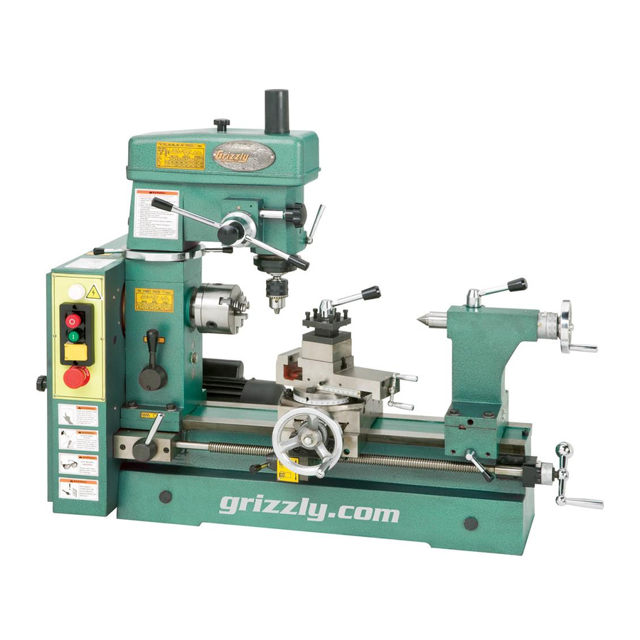
- Page 1 MODEL G4015Z COMBINATION LATHE/MILL OWNER'S MANUAL COPYRIGHT © MARCH, 2002 BY GRIZZLY INDUSTRIAL, INC. REVISED MAY, 2007 (TR) WARNING: NO PORTION OF THIS MANUAL MAY BE REPRODUCED IN ANY SHAPE OR FORM WITHOUT THE WRITTEN APPROVAL OF GRIZZLY INDUSTRIAL, INC.
- Page 2 Must be read and understood for your own safety. important: Keep this update with the owner's manual for future reference. For questions or help, contact our Tech Support at (570) 546-9663 or techsupport@grizzly.com. new feed rate & threading chart...
- Page 3 ���� ������ �������� �������� ������ ������������ �� ��� ������ ������ ���������� ����������� ��� ������� �� ���� ������������������ ������� �� ����� ���������� ��� ������ ��� ������������ ����� �� ���� ������ ��� ������ �� ������� �������� ������� ��������� ����������� ������������� �� ������ ���...
-
Page 4: Table Of Contents
Table Of Contents PAGE SAFETY SAFETY RULES FOR POWER TOOLS ....................2-3 ADDITIONAL SAFETY INSTRUCTIONS FOR LATHE/MILLS ..............4 CIRCUIT REQUIREMENTS 110V OPERATION ..........................5 EXTENSION CORDS ..........................5 GROUNDING ............................6 INTRODUCTION COMMENTARY............................7 UNPACKING ............................8 PIECE INVENTORY ..........................8 LIFTING ..............................9 CLEAN UP............................10 SITE CONSIDERATIONS ........................10 IDENTIFICATION MACHINE TERMS..........................11 ASSEMBLY &... -
Page 5: Safety
SECTION 1: SAFETY For Your Own Safety Read Instruction Manual Before Operating This Equipment The purpose of safety symbols is to attract your attention to possible hazardous conditions. This manual uses a series of symbols and signal words which are intended to convey the level of importance of the safety messages. - Page 6 Safety Instructions For Power Tools 9. USE PROPER EXTENSION CORD. Make 15. USE RECOMMENDED ACCESSORIES. sure your extension cord is in good condi- Consult the owner’s manual for recom- tion. Conductor size should be in accor- mended accessories. The use of improper dance with the chart below.
-
Page 7: Additional Safety Instructions For Lathe/Mills
Additional Safety Instructions For Lathe/Mills MAKE SURE ALL GUARDS are in place NEVER OPERATE THE LATHE/MILL and that the lathe/mill sits on a flat, stable WITH DAMAGED OR WORN PARTS. surface. Maintain your lathe/mill in proper working condition. Perform routine inspections and BEFORE STARTING THE MACHINE be maintenance promptly when called for. -
Page 8: Circuit Requirements 110V Operation
SECTION 2: CIRCUIT REQUIREMENTS Extension Cords 110V Operation The Model G4015Z Lathe/Mill is wired for 110 If you find it necessary to use an extension cord volt, single phase operation. The ⁄ H.P. motor with the Model G4015Z, make sure the cord is will safely draw 8.7 amps at 110V. -
Page 9: Grounding
Grounding In the event of an electrical short, grounding reduces the risk of electric shock by providing a path of least resistance to disperse electric cur- rent. This tool is equipped with a power cord hav- ing an equipment-grounding conductor. See Figure 1. -
Page 10: Introduction Commentary
The electrical package consists of a ⁄ H.P., any time with no obligation on the part of Grizzly. 110V motor, reversing switch and cord set. Whenever possible, though, we send manual updates to all owners of a particular tool or machine. -
Page 11: Unpacking
Unpacking Piece Inventory The Model G4015Z is, for the most part, pre- This combination lathe/mill is shipped from the assembled at the factory. Inside the crate you’ll manufacturer in a carefully packed crate. If you find: discover the machine is damaged after you’ve signed for delivery, and the truck and driver are gone, you will need to file a freight claim with the •... -
Page 12: Lifting
Lifting Machine The Model G4015Z is a heavy machine, 440 lbs. shipping weight. The Model G4015Z requires the use of lifting NOT move the machine equipment such as a fork lift, engine hoist or by yourself – you will boom crane. Do Not lift the machine by hand. need assistance See the warning at the right. -
Page 13: Clean Up
" footprint. Most commercial or vent cleaner or citrus-based degreaser, like garage shop floors should be sufficient to carry Grizzly’s G7895 Citrus Engine Degreaser. Avoid the weight. Before moving the Lathe/Mill onto a chlorine-based solvents as they may damage residential floor, inspect it carefully to determine painted surfaces should they come in contact. -
Page 14: Identification
SECTION 4: IDENTIFICATION Figure 3. The following is a list of controls and components on the Model G4015Z. Please take time to become familiar with each term and its location. These terms will be used throughout the manual and know- ing them will aid in comprehension. -
Page 15: Assembly & Setup
SECTION 5: ASSEMBLY & SETUP This section will cover the basics in assembly and setup. We recommend you complete assembly in the order in which it is presented to achieve the best results. Do not connect the machine to power at this time. -
Page 16: Lathe Chuck
Figure 6. Rotating the key clockwise closes the jaws. Grizzly offers 4-jaw chucks. Please note that a 5" adapter plate has been provided for mounting a 4-jaw chuck. Please see Grizzly’s current catalog for ordering information on 4-jaw chucks. -
Page 17: Lathe Chuck Removal
Lathe Chuck Removal To remove a chuck: Place a piece of plywood across the lathe bed and position it just under the chuck. The board should be at least 8" wide and 10" long. ALWAYS place a piece Locate the 3 socket head cap screws on the of plywood over the back of the back plate and remove 2 of them. - Page 18 To install a chuck: Chuck and back plate join here. Place a piece of plywood across the lathe bed and position it just under the spindle. Place a socket head screw into one of the holes in the back plate. Lift the chuck up to the spindle and align the threaded hole in the back of the chuck with the screw.
-
Page 19: Dead Center
The tailstock barrel and center have a Morse Dead Center Taper #3. Before assembling these, insure that the mating surfaces are “white glove” clean. Clean the mating surfaces so they are free of dirt and oil. These parts will last longer and remain The dead center is used to support stock which is accurate when properly cleaned before assem- too long to be supported by the chuck alone. -
Page 20: Tool Post
Tool Post The Model G4015Z comes supplied with a 4 way turret tool post. It is designed to accept up to 4- ⁄ " tool bits. Other devices and holders may be installed into the tool post and arranged as in Figure 9. -
Page 21: Drill Chuck
Drill Chuck Drill Chuck Removal The Model G4015Z comes supplied with a drill To remove the drill chuck from the drill press: chuck and arbor that can be used in the tailstock on the lathe or in the spindle for the drill press. Unplug the machine. -
Page 22: Drill Press Mounting
Drill chuck arbors with a standard tang (or flat) on the small end allow the operator to simply turn the tailstock handwheel counterclockwise until the drill chuck and arbor pop loose. Grizzly offers a variety of chucks and arbors. Please see our current catalog for more information. -
Page 23: Machine Vise
Machine Vise The Model G4015Z comes supplied with a milling vise which also serves as the compound for the lathe. The 4-way tool post must be removed before using the vise. Loosen the lock handle and slide the tool post off of the compound/vise as in Figure 13. -
Page 24: Lathe Controls Lathe Speeds
SECTION 6: LATHE CONTROLS the motor pulley. Lathe Speeds Place the upper belt in the desired position. Place the bottom belt in the desired pulleys. Before using the lathe, the hub on the end of the lathe spindle must be pulled out as shown in Pull tension on the upper belt with the middle Figure 15. -
Page 25: Feed Selection
Feed Selection Feed Lever Never move the feed rate lever while machine While the Lead Screw can be placed in neutral is running. with the feed selection lever, another lever allows the power feeding feature of the lathe to be The Model G4015Z Lathe/Mill has 2 feed control turned on and off. -
Page 26: Half Nut
Half Nut Carriage Controls The half nut lever is located under the left hand The lathe has 3 handles for manual control of the side apron as shown in Figure 19. This handle tool bit during machining operations. One full turn may be engaged and disengaged while the on the cross slide or longitudinal hand cranks will machine is running and while making a cut. -
Page 27: Tailstock Controls
Tailstock Controls Cross Slide - This hand wheel moves the com- pound slide across the lathe bed. Turning the dial clockwise moves the slide away from the opera- tor. The motion of this slide is used for facing a The tailstock comes supplied with a handwheel workpiece and when advancing a cut for reducing with graduated dial, barrel lock, tailstock lock and a diameter. -
Page 28: Drill Press Controls
SECTION 7: DRILL PRESS CONTROLS Drill Press Speeds ������������������ ����� ������� ������ The speed of the drill press spindle is controlled ���� ��� ��������� � ��� � by 2 groups of belts and pulleys. The belt posi- � tions on the end of the lathe control one speed ������... -
Page 29: Fine Down Feed
To change belt position: Fine Down Feed Unplug the machine. Remove the Upper Belt Guard, loosen the The up and down motion of the drill press spin- cover securing stud and pivot the belt ten- dle is controlled just like any other drill press with sioner to relax tension on the belt. -
Page 30: Adjustments
SECTION 8: ADJUSTMENTS Gibs There are three gib adjustments for the Model G4015Z. They are: the cross-slide gib, the com- pound slide gib and the apron gib. Cross-slide Gib - The gib on the cross-slide is adjusted by tightening or loosening the 4 setscrews located on the right hand side of the slide. -
Page 31: Head Stock
Apron Gib - There are 2 setscrews that tension Head Stock the saddle gib. Before making adjustments to the saddle gib, ensure that the front lock lever is loose by turning it counterclockwise. See Figure The Head Stock can be adjusted up or down to suit height requirements for different workpieces. -
Page 32: Tailstock
Place a center in your tailstock. Tailstock Attach a lathe dog to the bar stock and mount it between the centers. See Figure The tailstock on the Model G4015Z is aligned with the headstock at the factory. However, we Turn approximately .010" off of the diame- recommended that you take the time to ensure ter. - Page 33 NOTICE Before making adjustments to the tailstock, mount a dial indictor so that the dial plunger is on the tailstock barrel. See Figure 34. Figure 35. Adjusting for tailstock end taper. 7. Loosen the 4 tailstock mounting bolts. Adjust the tailstock offset by the amount of the taper by turning the adjustment setscrews.
-
Page 34: Operations
SECTION 9: OPERATIONS Power indicator light – shines when power is Control Panel turned on using the system reset switch. Motor off button – turns motor off. It is vital that you become familiar with the control panel before operating the Model G4015Z. Motor on button –... -
Page 35: Test Run
If the direction is reversed, contact our service Test Run department for further instructions. If the lathe/mill is running correctly, push the stop button, wait for the machine to come to a complete stop and take some time to review the various controls. Inspect your machine for loose nuts and bolts, and ensure no tools are left in... -
Page 36: Reading The Charts
Feed Rates Reading the Charts Gearing for feed rates are detailed in Figure 38. Charts for the powerfeed and thread cutting fea- In the example below we will be selecting gears tures are located on the inside of the Lower Belt for a feed rate of 0.002"... -
Page 37: Changing Gears
Changing Gears Changing gears on the Model G4015Z is straight forward. Refer to the label found inside of the Lower Belt Guard for proper gear selection while following the example below. We will be changing the gears to those that would be used to set the machine for a 0.002"... - Page 38 gear support arm and loosely fasten the Bushing assembly to the tee-nut using the cap screw. Figure 41 shows the proper sequence. Slide Tee-Nut the combination gear along the slot in the support arm until gear C meshes with gear D, as in Figure 42, and tighten the cap screw.
-
Page 39: Inch Threading
The Model G4015Z is capable of cutting many Inch Threading standard inch and metric threads. Follow the pro- cedures listed in Changing Gears in the previous section and change the gears according to the chart for the thread desired. Figures 45 - 48 The inch threading gear chart is illustrated in show the order the gears should be installed. - Page 40 Figure 47. 30 tooth gear installed at “D”. Figure 46. 125/127 tooth combination gear. Figure 48. 30 tooth gear installed at “D”. G4015 Lathe/Mill -37-...
-
Page 41: Power Feed
Example: Metric Threading To cut a thread with a pitch of 0.5 mm we would select a 60 tooth gear and place it in the A posi- tion; we would select a 30 tooth gear and place it The metric threading gear chart is illustrated in in the D position and we would use the 60/120 Figure 49. -
Page 42: Maintenance
SECTION 10: MAINTENANCE Disconnect power to the machine when perform- ing any adjustments or maintenance. Failure to do this may result in seri- ous personal injury. Lubrication Your Model G4015Z will function best when it is clean and well lubricated. Take the time to wipe Figure 52. -
Page 43: Bearing Preload
Tailstock - The tailstock is fitted with 2 oiling Motor - The bearings used in the motor are ports. The tailstock barrel may be oiled directly. shielded and lubricated for life, therefore, no Apply oil each week, or after every five uses lubrication is necessary. -
Page 44: Closure
However, due to Grizzly’s policy of contin- good places to start. uous improvement, changes may be made at any time with no obligation on the part of Grizzly. Whenever possible, though, we send manual updates to all owners of a particular tool or As with all power tools, there is danger machine. -
Page 45: Machine Data
MACHINE DATA SHEET Customer Service #: (570) 546-9663 • To Order Call: (800) 523-4777 • Fax #: (800) 438-5901 GRIZZLY MODEL G4015Z COMBO LATHE/MILL Overall Dimensions: Overall Length ......................42" Overall Width ......................23" Overall Height ......................35" Bed Width ........................5 ⁄ "... -
Page 46: Your Notes
Your Notes G4015 Lathe/Mill -43-... -
Page 47: Parts Breakdown And Parts Lists
-44- G4015 Lathe/Mill... - Page 48 PART # DESCRIPTION PART # DESCRIPTION PFH07M FLAT HD SCR M5-.8 X 8 P4015Z001 PIN 8 X 30 P4015Z061 V-BELT 710 P4015Z002 LINK BOARD P4015Z062 PULLEY P4015Z003 SPRING PIN P4015Z063 SHAFT P4015Z004 PIN 12 X 40 P4015Z064 COVER P4015Z006 SPRING PS07M PHLP HD SCR M4-.7 X 8 P4015Z007 STEEL BALL 5MM...
- Page 49 -46- G4015 Lathe/Mill...
- Page 50 PART # DESCRIPTION P4015Z026 CLUTCH PK40M KEY 8 X 8 X 12 P4015Z028 CLUTCH P4015Z029 TAB WASHER 30 P4015Z030 ROUND NUT PSS26M SETSCREW M5-.8 X 6 P4015Z032 HANDLE KNOB P4015Z037 BEARING D2007107 P4015Z038 COMP WASHER P4015Z039 SLEEVE P4015Z040 BEVEL GEAR P4015Z041 BEARING P4015Z042...
- Page 51 -48- G4015 Lathe/Mill...
- Page 52 PART # DESCRIPTION PART # DESCRIPTION P4015Z801 STRAIN RELIEF P4015Z101 MOTOR P4015Z802 PLASTIC HOUSING PSS20M SET SCREW M8-1.25 X 8 P4015Z803 SWITCH ASSEMBLY P4015Z103 PULLEY PK23M KEY 5 X 5 X 25 P4015Z804 SAFETY SWITCH P4015Z805 SPACER PB07M HEX BOLT M8-1.25 X 25 PLW04M LOCK WASHER 8MM P4015Z806...
- Page 53 -50- G4015 Lathe/Mill...
- Page 54 PART # DESCRIPTION PART # DESCRIPTION 130 P4015Z130 BODY 165 P4015Z165 HALF NUT 131 P4015Z131 CLUTCH B 166 P4015Z166 HALF NUT BASE 132 P4015Z132 CLUTCH A 167 P4015Z167 HALF NUT BRACKET 133 PRP25M ROLL PIN 5 X 21 168 PSS14M SET SCREW M8-1.25 X 12 134 P4015Z134 SLEEVE (LEFT)
- Page 55 265A 265B -52- G4015 Lathe/Mill...
- Page 56 PART # DESCRIPTION PART # DESCRIPTION P4015Z255 KNOB P4015Z100 DRAW BAR PRP16M ROLL PIN 3 X 25 P4015Z200 LEAD SCREW SLEEVE P4015Z257 KNOB PSB24M CAP SCREW M5-.8 X 16 P4015Z258 LEVER PW02M FLAT WASHER 5MM P4015Z259 PIN P4015Z203 CIRCLIP P4015Z261 WORM SHAFT P4015Z204 BEVEL GEAR P4015Z262 OILER P4015Z205 COMP WASHER...
- Page 57 -54- G4015 Lathe/Mill...
- Page 58 PART # DESCRIPTION P4015Z401 WASHER P4015Z402 LOCKING HUB P4015Z403 LEVER P4015Z404 KNOB P4015Z405 SQUARE HEAD BOLT P4015Z406 TOOL POST P4015Z407 HOLLOW SET PIN P4015Z408 SPRING P4015Z409 TOOL POST BASE P4015Z410 PS02M PHLP HD SCR 4-.7 X 12 P4015Z412 TOOL POST BOLT P4015Z413 CHELA PSB26M...
- Page 59 -56- G4015 Lathe/Mill...
- Page 60 PART # DESCRIPTION P4015Z153 KNOB P4015Z154 LEVER P4015Z155 LOCK HUB P4015Z179 ACORN NUT P4015Z189 LOCK PIN PSS06M SET SCREW M8-1.25 X 16 PSS21M SETSCREW M8-1.25 X 25 P4015Z192 TAILSTOCK BASE P4015Z193 P4015Z541 TAILSTOCK BODY PB31M HEX BOLT M10-1.5 X 40 PSS23M SETSCREW M4-.7 X 8 P4015Z545...
-
Page 61: Warranty And Returns
WARRANTY AND RETURNS Grizzly Imports, Inc. warrants every product it sells for a period of 1 year to the original purchaser from the date of purchase. This warranty does not apply to defects due directly or indirectly to misuse, abuse, neg- ligence, accidents, repairs or alterations or lack of maintenance. -
Page 62: Warranty Card
The following information is given on a voluntary basis. This information will be used for marketing purposes to help Grizzly develop better products. Your name will be included in our mailing list only. It will not be sold to other com- panies. - Page 63 FOLD ALONG DOTTED LINE Place Stamp Here GRIZZLY INDUSTRIAL, INC. P.O. BOX 2069 BELLINGHAM, WA 98227-2069 FOLD ALONG DOTTED LINE Send a Grizzly Catalog to a friend: Name_______________________________ Street_______________________________ City______________State______Zip______ TAPE ALONG EDGES--PLEASE DO NOT STAPLE...