Advertisement
Quick Links
1
DS-KIS702Y(-P)
Video Intercom Two-Wire Kit
UD29996B
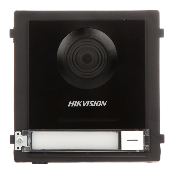
KD8003Y-IME2
Two-Wire Module Door Station
Diagram References
Appearance
1
3
1
Microphone
2
Low Illumination IR Supplement Light
Built-in Camera
4
Loudspeaker
5
Call Button
6
Nametag
7
TAMPER
8
Two-Wire Interface
9
Module-connecting Interface
10
Terminals
Note: The module-connecting interface is used to connect other function module, such as nametag module, keypad
module, card reader module, etc. All these modules are known as sub module.
2
Terminal
A1
B1
AIN2: For the access of Door Contact 2
NC1: Door Lock Relay Output (NC)
AIN1: For the access of Door Contact 1
A2
B2
NO1: Door Lock Relay Output (NO)
AIN3: For the access of Exit Button 1
A3
COM: Common Interface
B3
A4
NC2: Door Lock Relay Output (NC)
B4
AIN4: For the access of Exit Button 2
A5
NO2: Door Lock Relay Output (NO)
B5
485-: Module-connecting Interface
GND: Grounding
485+: Module-connecting Interface
A6
B6
A7
12 VDC: Power Output
B7
12V OUT: Module-connecting Interface
A8
GND: Grounding
B8
GND: Module-connecting Interface
Two-Wire Interface
C
3
Installation
Note: Video intercom module door sta�on support one-module installa�on, two-module installa�on, three-
module installa�on and more-than-three-module installa�on. Here takes three-module installa�on as an example.
Before you begin:
1. Tools that you need to prepare for installation: Drill (6), cross screw driver (PH1*150 mm), and gradienter.
2. Make sure all the related equipment is power-off during the installation.
3. Make sure you have configured the sub module address before installation. Valid sub module address range is
1 to 8. The No. should be unique for sub modules that connected to the same main unit. The sub module
3
address and corresponding switch status is shown as the figure.
Sub Module
Address
DIP 1 DIP 2 DIP 3 DIP 4 DIP 5 DIP 6 DIP 7 DIP 8
Module 1
ON
OFF
OFF
OFF
OFF
OFF
OFF
OFF
Module 2
OFF
ON
OFF
OFF
OFF
OFF
OFF
OFF
Module 3
ON
ON
OFF
OFF
OFF
OFF
OFF
OFF
Module 4
OFF
OFF
ON
OFF
OFF
OFF
OFF
OFF
Module 5
ON
OFF
ON
OFF
OFF
OFF
OFF
OFF
Module 6
OFF
ON
ON
OFF
OFF
OFF
OFF
OFF
Module 7
ON
ON
ON
OFF
OFF
OFF
OFF
OFF
Module 8
OFF
OFF
OFF
ON
OFF
OFF
OFF
OFF
Three-Module Flush Mounting
1. Cave the installation hole, and pull the cable out.
Note: The suggested dimension of the installation hole is 321.8(W) × 108(H) × 45.5(D) mm. The suggested length of the
cables left outside is 270 mm.
2. Select a cable entry and remove the plastic sheet. Route the cables through the gang box hole. Insert the
gang box into the installation hole. Mark the gang box screw holes' position with a marker, and take out the
gang box.
3. Drill 4 holes according to the marks on the wall, and insert the expansion sleeves into the screw holes.
Fix the gang box with 4 expansion bolts.Fill the gap between the gang box and wall with concrete or Silicone
sealant. Remove the mounting ears
with tool after concrete is dry.
4. Connect cables and insert the modules.
a.Connect Cable 1 and one end of Cable 2 to the corresponding interfaces of the main unit, then insert the
main unit into the upper grid.
b.Connect the other end of Cable 2 to the input interface of Sub Module 1. Connect one end of Sub Module
1 and insert it into the middle grid.
c.Connect the other end of Cable 3 to the input interface of Sub Module 2. Insert it into the bottom grid.
5. Fix the cover and the main unit with 2 socket head cap screws by using a hexagon wrench.
Three- Module Surface Moun�ng
1. Paste the installa�on s�cker 1 onto the wall. Make sure the s�cker is placed
horizontally via measuring with the gradienter. Drill 4 holes according to the screw holes
on the s�cker.
3
Note: The suggested size of hole is 6(diameter) × 25(depth) mm. The suggested length of the cables le�
outside is 270 mm.
2. Remove the s�cker and insert the expansion sleeves into the screw holes. Fix the
moun�ng frame onto the wall with 4 expansion bolts.
3. Thread the module-connec�ng line across the thread holes of the frame. Pass the
main unit connec�ng line across the thread hole to the top grid and connect the cables.
a.Connect the lines and module-connec�ng line 1 to the corresponding interfaces of
the main unit, then place the main unit into the upper grid.
b.Connect the other end of the module-connec�ng line 1 to the input interface of the
sub modules via module-connec�ng line 2.
c.Organize the cables with cable �e in the package.
4. Insert the modules into the frame a�er wiring. The main unit must be placed in the
top grid.
5. Use the hexagon wrench in the package to fix the cover onto the frame.
4
Installation Positions
Recommended Installation Height (The distance between the camera and the ground): 1.4 m to 1.6 m
The FOV of the camera is :
Horizontal:
146°,
Vertical: 82°.
The highest visual height and lowest visual height of the camera is shown as picture.
Note:
The power source should be qualified and meet limited power
source or PS2 requirements according to IEC 60950-1 or IEC 62368-1 standard.
2
1
2
Gang Box
Expansion Bolt
1
2
Module-Connec�ng
Line1
Module-Connec�ng
Line2
3
4
1
Main Unit
2
1
2
2
Sub Module 1
3
3
3
Sub Module 2
Moun�ng Ear
3
4
Moun�ng Frame
Main Unit
Hexagonal
Screw
Thread Hole
Cables
Connected
to Main
Unit
Sub Module
4
Scan the QR code to get User Manual for details.
5
Hexagonal
Screw
5
Cover
Hexagon Wrench
Recommended Installation Height (The distance
between the camera and the ground): 1.4 m to 1.6 m
1.4 m
1.5 m
Advertisement

Related Manuals for HIKVISION DS-KIS702Y


Summary of Contents for HIKVISION DS-KIS702Y
- Page 1 DS-KIS702Y(-P) Recommended Installation Height (The distance between the camera and the ground): 1.4 m to 1.6 m Scan the QR code to get User Manual for details. Video Intercom Two-Wire Kit UD29996B KD8003Y-IME2 Two-Wire Module Door Station Diagram References Appearance...
- Page 2 3. Fix the wall mounting plate to the junction box with 2 screws. The power adapter is contained only in the DS-KIS702Y-P Kit. 4. Hook the indoor station to the wall mounting plate tightly by inserting the plate hooks into the slots on the rear panel of the indoor station, during which the lock catch will be locked automatically.