Grizzly G4003 Manual Insert
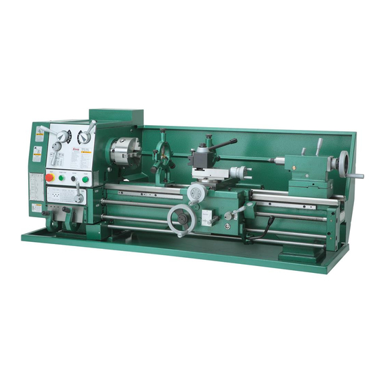
Gear head metal lathe
Hide thumbs
Also See for G4003:
- Owner's manual (60 pages) ,
- Parts list (19 pages) ,
- Read this first manual (18 pages)
Table of Contents
Advertisement
model g4002/g4003
gear head metal
lathe
manual insert
the Model g4002/g4003 lathe is shipped without oil. you must fill the headstock and apron with oil, and
complete the lubrication procedures outlined in the maintenance section on page 27. if you run this
lathe without oil, even for a short period of time, drivetrain parts will be damaged and your lathe warranty
will be void. We recommend using iso 68 or a good grade non-detergent sAe 30W motor oil in your lathe.
Make sure to change the oil immediately after lathe break-in.
If you have any questions about this manual insert or machine lubrication and break-in, please contact
Grizzly Technical Support at (570) 546-9663 or email techsupport@grizzly.com.
GEARBOXES MUST
BE FILLED WITH OIL!
NO OIL SHIPPED WITH
MACHINE!
Requires ISO 68
or Non-Detergent
SAE 30W Motor Oil.
Copyright © MArCh, 2008 By grizzly industriAl, inC.
Warning: no portion of this manual may be reproduced in any shape
or form Without the Written approval of grizzly industrial, inc.
#Cr10598 printed in ChinA
Advertisement
Table of Contents

Related Manuals for Grizzly G4003


Summary of Contents for Grizzly G4003
- Page 1 Model g4002/g4003 lathe is shipped without oil. you must fill the headstock and apron with oil, and complete the lubrication procedures outlined in the maintenance section on page 27. if you run this lathe without oil, even for a short period of time, drivetrain parts will be damaged and your lathe warranty will be void.
- Page 2 MODEL G4002 / G4003 INSTRUCTION MANUAL COPYRIGHT © 2000 BY GRIZZLY INDUSTRIAL, INC. WARNING: NO PORTION OF THIS MANUAL MAY BE REPRODUCED IN ANY SHAPE OR FORM WITHOUT THE WRITTEN APPROVAL OF GRIZZLY INDUSTRIAL, INC. REVISED JANUARY, 2000 PRINTED IN CHINA...
-
Page 4: Table Of Contents
SAFETY SAFETY RULES FOR POWER TOOLS ...2-3 ADDITIONAL SAFETY INSTRUCTIONS FOR METAL LATHES ...4 CIRCUIT REQUIREMENTS 220V OPERATION ...5 EXTENSION CORDS ...5 GROUNDING ...5 INTRODUCTION COMMENTARY...6 UNPACKING ...7 PIECE INVENTORY ...7 CLEAN UP...8 SITE CONSIDERATIONS ...8 ASSEMBLY & SETUP MOUNTING ...9 LUBRICATION ...9 CHUCKS ...9-10 LIVE CENTER ...10... -
Page 5: Safety
SECTION 1: SAFETY For Your Own Safety Read Instruction Manual Before Operating This Equipment The purpose of safety symbols is to attract your attention to possible hazardous conditions. This manual uses a series of symbols and signal words which are intended to convey the level of importance of the safety messages. - Page 6 Safety Instructions For Power Tools 9. USE PROPER EXTENSION CORD. Make sure your extension cord is in good condi- tion. Conductor size should be in accor- dance with the chart below. The amperage rating should be listed on the motor or tool nameplate.
-
Page 7: Additional Safety Instructions For Metal Lathes
Additional Safety Instructions For The Lathe MAKE SURE ALL GUARDS are in place and that the lathe sits on a flat, stable sur- face. BEFORE STARTING THE MACHINE be certain the workpiece has been properly engaged in the chuck and tailstock center (if in use) and that there is adequate clearance for full rotation. -
Page 8: Circuit Requirements 220V Operation
SECTION 2: CIRCUIT REQUIREMENTS 220V Operation The Model G4002/3 is wired for 220 volt, single phase operation. The 2 HP motor will safely draw 9 amps at 220V. A 10-amp fuse or circuit break- er should be used when connecting this metal lathe. -
Page 9: Introduction Commentary
We are proud to offer the Grizzly Model G4002 / G4003 Gear Head Metal Lathe. The Model G4002 / G4003 is part of a growing Grizzly fami- ly of fine metalworking machinery. When used according to the guidelines set forth in this man-... -
Page 10: Unpacking
Customer Service. The G4002 and G4003 are heavy machines (1015 lbs. and 1040 lbs. shipping weight). DO NOT over-exert yourself while unpacking or moving your machine –... -
Page 11: Clean Up
Grizzly catalog. If you choose to use the stand, you will find the holes for bolt- ing the G4002/3 to the stand are already in place. -
Page 12: Assembly & Setup Mounting
This lathe should be securely mounted to a stand or bench top. An accessory stand is available from Grizzly, please see our current catalog for pricing. There are 2 holes in the base at the tail- stock end of the lathe and four holes on the gear- head end which can be used to secure the machine to a stand. - Page 13 To remove a chuck: 1. Place a piece of plywood across the lathe bed and position it just under the chuck. The board should be at least 8" wide and 10" long. Never leave a chuck key in the chuck when it is not in use.
-
Page 14: Live Center
Live Center The live center is used to support stock which is too long to be supported by the chuck alone. Stock protruding more than three times its diam- eter should be supported by the live center. Figure 4. Live center installed in tailstock. The tailstock barrel and live center have a Morse taper #3. -
Page 15: Follow Rest
Follow Rest The follow rest is normally used with small diam- eter stock to prevent the workpiece from “spring- ing” under pressure from the turning tool. To install the follow rest: 1. The follow rest is secured to the saddle with two cap screws. -
Page 16: Controls Spindle Speeds
SECTION 5: CONTROLS Spindle Speeds Never change speeds while spindle or motor is in motion. The speed of the spindle is controlled by the positions of the speed control knobs. See Figure 7. By positioning the knobs using the chart in Figure 8, you can achieve all of these speed ranges: 70, 200, 220, 270, 360, 600, 800, 1000 and 1400 RPM. -
Page 17: Feed Direction
Feed Direction Never move selection levers while machine is running. The G4002/3 Metal Lathe can cut left or right while feeding or threading and across both ways for fac- ing operations. This feed direction is controlled by the selection knob as shown in Figure 9. Figure 9. -
Page 18: Quick Change Selection
Figure 11. Feed rate selector levers. Important: Do not force any selection lever on the machine. If the lever will not engage, rotate the chuck by hand while keeping light pressure on the selector. As the chuck rotates, it aligns the gears and the selector will engage. -
Page 19: Thread Selection
Thread Selection Inch thread selection: To cut threads with inch pitches, a selection must be made for feed direction, pitch and lead screw. Select the desired direction of cut as described in the section titled Feed Direction. Rotate the Feed/Lead Screw selection lever to the position shown in Figure 14. - Page 20 NOTICE The threading dial cannot be used when cut- ting metric threads. Once the half nut has been engaged, it must remain engaged throughout the threading process. Half Nut Lever - This lever compresses and releases the half nut that engages the leadscrew. See Figure 16.
- Page 21 Metric thread selection: The chart in Figure 17 lists 29 metric threads that can be cut on the G4002/3. Five ranges are used on the left hand quick change selector and 6 on the right hand quick change selector. Additionally, 5 gear changes are necessary to accomplish all of the available metric threads.
- Page 22 Thread Selection Cont. Metric threading requires 5 gear changes to achieve all of the available pitches listed on the chart. Refer to Figure 19 while reading the instructions below. To change gears: 1. Loosen the nut below the middle gear and rotate the bracket so the middle gear moves away from gear F.
-
Page 23: Carriage Controls
Carriage Controls The carriage handwheel allows the cutting tool to move along the length of the lathe bed. The cross slide allows the cutting tool to travel per- pendicular to the bed. The carriage features a top slide which allows linear movement of the cutting tool at any preset angle. -
Page 24: Toolpost
More styles of tool holders are available through Grizzly Industrial, Inc. Consult the latest catalog for styles, prices and ordering information. Figure 22. Quick change tool post. -
Page 25: Test Run
Test Run Always make sure the power switch is in the “OFF” position and the spindle control lever is in the neutral position before plugging in power cord. Now that the lathe is securely in place and you’ve read the safety guidelines, it’s time to give the machine a test run. -
Page 26: Adjustments
SECTION 6: ADJUSTMENTS Gibs There are three main gib adjustments for the Model G4002/3. They are: the cross-slide gib, the compound slide gib and the saddle gib. Cross-slide Gib - The gib on the cross-slide is adjusted by the two screws located at each end. See Figure 25. -
Page 27: Steady Rest/Follow Rest
Saddle Gib - The saddle is supplied with a square head bolt on the front right hand side of the slide. Before making adjustments to the sad- dle gib, ensure that this bolt is loose by turning it counter clockwise. See Figure 26b. It is important that the apron gib be properly adjusted. -
Page 28: Tailstock
Tailstock The tailstock on the Model G4002/3 is aligned at the factory with the headstock. It is recommend- ed that you take the time to ensure that the tail- stock is aligned to your own desired tolerances. To align the tailstock: 1. -
Page 29: Tailstock
If the stock is thinner at the tailstock end, the tailstock needs to be moved away from the operator by at least the amount of the taper. See Figure 31. Figure 31. Adjusting for tailstock end taper. 7. Loosen the tailstock mounting bolt. Adjust the tailstock offset by the amount of the taper by turning the adjustment setscrews. -
Page 30: Maintenance
SECTION 7: MAINTENANCE ALWAYS disconnect the electric power to the machine before servicing. NEVER lubri- cate your lathe while it is running. Lubrication Your Model G4002/3 will function best when it is clean and well lubricated. Take the time to wipe down and oil the machine after use. -
Page 31: Bearing Preload
Slides and Ways - Apply oil to the ways and slides after each use. Wipe the ways with a clean rag prior to lubrication to ensure that no grime is carried along with your lubricant into friction-sen- sitive areas. Applying oil to the bedways and other bare metal parts also protect the lathe from rust and pitting. -
Page 32: Closure
However, due to Grizzly’s policy of contin- uous improvement, changes may be made at any time with no obligation on the part of Grizzly. Whenever possible, though, we send manual updates to all owners of a particular tool or machine. -
Page 33: Machine Data
Customer Service #: (570) 326-3806 • To Order Call: (800) 523-4777 • Fax #: (800) 438-5901 GRIZZLY MODEL G4002 12" X 24" GEAR HEAD LATHE Design Type ...Floor Model Overall Dimensions: Overall Length ...53" Overall Width ...26" Height With Optional Stand ...52 Height Without Optional Stand ...23"... -
Page 34: Machine Data
Customer Service #: (570) 326-3806 • To Order Call: (800) 523-4777 • Fax #: (800) 438-5901 GRIZZLY MODEL G4003 12" X 36" GEAR HEAD LATHE Design Type ...Floor Model Overall Dimensions: Overall Length ...61" Overall Width ...23" Height With Optional Stand ...54 Height W⁄O Optional Stand ...23"... -
Page 35: Parts Breakdown And Parts Lists
Electrical Components -32- G4002/3 Gear Head Lathes... - Page 36 G4002/3 Gear Head Lathes PART # DESCRIPTION P4002001 START BUTTON P4002002 INDICATOR LIGHT P4002003 JOG BUTTON P4002004 RESET BUTTON P4002050 THERMAL PROT. BLOCK P4002051 TRANSFORMER P4002052 MAGNETIC CONTACTOR P4002053 MAGNETIC CONTACTOR P4002054 FUSE HOLDER P4002055 CONTROL PANEL PLATE P4002933 FUSE 2 AMP -33-...
- Page 37 -34- G4002/3 Gear Head Lathes...
- Page 38 PART # DESCRIPTION P4002101 SCREW P4002102 COVER P4002103 OIL SEAL P4002104 SPINDLE P7212 BEARING D-7212 P4002106 P4002107 P4002108 SCREW P4002109 GEAR P4002110 GEAR P4002111 GEAR P4002112 P4002113 SCREW P4002114 P4002115 COLLAR P4002116 SCREW P4002117 GEAR P7211 BEARING D-7211 P4002119 P4002120 OIL SEAL P4002121 COVER...
- Page 39 z178 1100 1101 1102 1103 1104 1104B P40021104B O-RING 1105 1106 1107 1108 1109 1110 1111 1112 1113 1114 1115 1116 1117 -36- PART # DESCRIPTION P4002178 ECCENTRIC SHAFT P4002179 GEAR P4002180 SCREW P4002181 P4002182 SHAFT P4002183 OIL SEAL P4002184 SHAFT ARM P4002185 C-CLIP...
- Page 40 207B P4002207B G4002/3 Gear Head Lathes PART # DESCRIPTION PSB26M CAP SCREW M6-1 X 12 P4002202 WASHER P4002203 GEAR PK12M KEY 5 X 5 X 30 PSB26M CAP SCREW M6-1 X 12 P4002206 WASHER STEP GEAR 86-91T P6202 BALL BEARING 6202 P4002210 QUADRANT P4002211...
- Page 41 -38- G4002/3 Gear Head Lathes...
- Page 42 PART # DESCRIPTION P4002301 LEAD SCREW P4002302 P8103 BEARING 8103 P4002305 SHAFT PK19M KEY 5 X 5 X 14 P4002308 GEAR PN09M HEX NUT M12-1.75 P4002310 WASHER P4002311 SCREW P4002312 COVER PK12M KEY 5 X 5 X 30 PK06M KEY 5 X 5 X 10 P4002315 SHAFT P4002316...
- Page 43 -40- G4002/3 Gear Head Lathes...
- Page 44 PART # DESCRIPTION P4002401 HANDLE P4002402 HAND WHEEL P4002403 INDEXING RING P4002404 P4002405 SCREW P4002406 BRACKET P4002407 GEAR SHAFT P4002408 BUSHING PRP05M ROLL PIN 5 X 30 P4002410 GEAR P4002411 RETAINING RING P4002412 GEAR SHAFT P4002413 GEAR P4002414 GEAR P4002415 P4002417 SHAFT P4002418...
- Page 45 -42- G4002/3 Gear Head Lathes...
- Page 46 529A P4002529A 530A P4002530A 531A P4002531A G4002/3 Gear Head Lathes PART # DESCRIPTION P4002501 SADDLE P4002502 SCREW P4002503 WIPER P4002504 SCREW P4002505 COVER P4002506 SCREW P4002507 WIPER P4002508 P4002509 SCREW P4002510 SCREW P4002511 SCREW P4002512 CROSS SLIDE P4002513 P4002514 BUSHING P4002515 P4002518 SLIDE PLATE...
- Page 47 615A P4002615A 616A P4002616A 617A P4002617A 618A P4002618A -44- PART # DESCRIPTION P4002601 SCREW P4002602 P4002603 COMPOUND SLIDE PN08M HEX NUT M10-1.25 P4002605 SCREW P4002606 SCREW P4002607 LEAD SCREW NUT P4002608 SCREW PN01M HEX NUT M6-1.0 P4002610 LEAD SCREW P8101 BEARING 8101 P4002612 BRACKET...
- Page 48 G4002/3 Gear Head Lathes -45-...
- Page 49 -46- PART # DESCRIPTION P4002701 CENTER P4002702 P4002703 QUILL P4002704 TAIL STOCK P4002705 BASE P4002706 SCREW P4002707 SCREW P4002708 P8101 BEARING 8101 P4002710 BRACKET P4002711 INDEX RING P4002712 SCREW P4002713 HAND WHEEL P4002714 HANDLE PN09M HEX NUT M12-1.75 P4002716 HANDLE P4002717 LOCK SCREW P4002718...
- Page 50 G4002/3 Gear Head Lathes PART # DESCRIPTION P4002801 COVER P4002802 SCREW P4002803 P4002812 MOTOR 2 HP PW04M FLAT WASHER 10MM P4002814 SCREW P4002815 P4002816 PULLEY P4002817 MOTOR MOUNT BRKT P4002818 FLAT WASHER P4002819 HEX BOLT -47-...
- Page 51 -48- PART # DESCRIPTION P4002901 BRACKET P4002902 SCREW P4002903 OIL CAP P4002904 P4002905 SCREW P4002906 COLLAR P4002907 P4002908 P4002909 P4002910 SPRING P4002911 HANDLE P4002912 BRACKET P4002913 SCREW P4002914 P4002915 BRACKET P4002916 C-CLIP PSB31M CAP SCR M8-1.25 X 25 P4002918 BRACKET 919A P4002919A FOR/REV SWITCH G4002/3 Gear Head Lathes...
- Page 52 1001 1002 1002B P40021002B RACK, GAP 1003 1004 1005 1008 1009 1010 1011 G4002/3 Gear Head Lathes PART # DESCRIPTION P40021001 LATHE BED P40021002 RACK P40021003 P40021004 SCREW P40021005 SCREW P40021008 CHIP PAN P40021009 WASHER P40021010 P40021011 SPLASH GUARD -49-...
-
Page 53: Warranty And Returns
WARRANTY AND RETURNS Grizzly Imports, Inc. warrants every product it sells for a period of 1 year to the original purchaser from the date of purchase. This warranty does not apply to defects due directly or indirectly to misuse, abuse, neg- ligence, accidents, repairs or alterations or lack of maintenance. -
Page 54: Warranty Card
The following information is given on a voluntary basis. This information will be used for marketing purposes to help Grizzly develop better products. Your name will be included in our mailing list only. It will not be sold to other com- panies. - Page 55 FOLD ALONG DOTTED LINE FOLD ALONG DOTTED LINE Send a Grizzly Catalog to a friend: Name_______________________________ Street_______________________________ City______________State______Zip______ GRIZZLY INDUSTRIAL, INC. P.O. BOX 2069 BELLINGHAM, WA 98227-2069 TAPE ALONG EDGES--PLEASE DO NOT STAPLE Place Stamp Here...