Advertisement
Quick Links
I.
DESCRIPTION
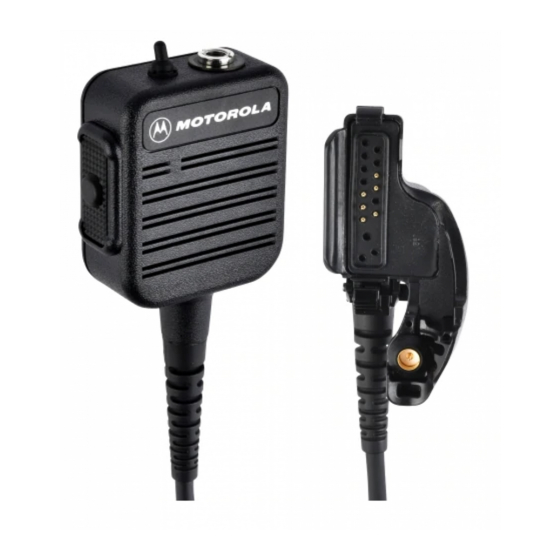
The NMN6247, NMN6250, and NMN6251 Public-Safety
Speaker/Microphones (PSSM) include a speaker, microphone,
push-to-talk (PTT) switch, high/low volume switch, swivel clip,
and cord connector assembly. All three models are exactly the
same, except that the PSSMs' cord lengths are different:
NMN6247 is 30", NMN6251 is 18", and NMN6250 is 24".
The PSSMs also have a threaded antenna jack located on top
of the housing, which accepts any of the following antennas:
Table 1. Antennas
Antenna
Frequency
Kit Number
NAE6546
UHF, 403-435 MHz
NAE6547
UHF, 435-470 MHz
NAE6548
UHF, 470-512 MHz
•
The antenna is not supplied with the PSSM kit; it
must be ordered separately.
•
It is not recommended to use these PSSMs with VHF
radios, since radio performance is reduced.
•
In shipping, a protective rubber seal (Motorola part
number 3205782P01) is inserted in the PSSM's
antenna port. Use this seal to cover the microphone's
antenna port when not in use.
The public safety speaker/microphone (PSSM) includes a
3.5mm earphone jack (J1) located on top of the accessory
connector. A seal, which is attached to the accessory
connector, is provided to cover the earphone jack when it is
not in use.
When the PSSM is attached to the radio, the speaker in the
radio is disabled, and the receiver audio is connected to the
accessory speaker. Similarly, the accessory microphone is
connected to the transmitter, and the accessory PTT switch
can now control the PTT function of the radio. The radio
microphone and PTT switch are still operational, but since the
radio speaker is disabled, you can listen to the received audio
only through the accessory speaker.
, and Motorola are trademarks of Motorola, Inc.
© 1997, 1998 by Motorola, Inc.
Radio Products Group
8000 W. Sunrise Blvd., Ft. Lauderdale, FL 33322
Printed in U.S.A. 4/98. All Rights Reserved.
Models: NMN6247, NMN6250, and NMN6251
Description
Insulator
Color Code
3" Helical
3" Helical
GREEN
3" Helical
BLACK
NOTES
II. PERFORMANCE TEST
A.
General
The PSSM's audio performance is designed to be similar to
that of the radio. The receive audio speaker loudness, with the
high/low switch on the PSSM set for "high," will equal or
exceed the loudness of the radio speaker.
The threaded antenna jack on the PSSM is not wired
as coaxial. Transmit power measurements should
read ZERO at this connector.
The threaded antenna jack (J2) on the PSSM is wired as center
and shield shorted together and connected to the radio
frequency (RF) coax cable center. The RF coax shield is
connected to printed circuit board (PCB) ground for best
RED
radiation performance.
B.
Audio test
The PSSM accessory can be checked for proper performance
by comparison with another new or known good unit on the
radio. Start each of the following two tests with the new or
known good unit on the radio, which must have an RF adapter
attached.
1.
Microphone - Transmit to a communications monitor
while voicing a tone or the spoken word "four." The
speaker/microphone should be held at a distance that
causes approximately 3kHz deviation (1.5kHz deviation
for 900Mhz radios). Repeat these conditions using the PSSM
to be tested. Good units compare to each other within
±2kHz deviation.
2.
Speaker - Using the communications monitor, generate
an RF signal to the radio. Set the modulation to a 1kHz
tone at 3kHz deviation (1.5kHz deviation for 900Mhz
radios). Set the high/low switch on the PSSM to "high."
Set the volume control on the radio to a loud, yet
undistorted, position. Without disturbing any settings,
repeat these conditions using the PSSM to be tested.
Good units should sound equally loud and undistorted.
The "low" setting loudness should compare as above.
C.
Antenna test
Refer to Table 1 and verify that the proper antenna is being
used. Use one of the following to conduct this test:
•
a communications monitor set to spectrum analyzer is
best,
•
a monitor receiver set to threshold squelch, or
•
a field strength meter.
PUBLIC-SAFETY
SPEAKER/MICROPHONE
NOTE
Service Manual
*6881085C36*
68P81085C36-A
Advertisement

Related Manuals for Motorola XTS Series


Summary of Contents for Motorola XTS Series
- Page 1 “four.” The • In shipping, a protective rubber seal (Motorola part speaker/microphone should be held at a distance that number 3205782P01) is inserted in the PSSM’s causes approximately 3kHz deviation (1.5kHz deviation...
- Page 2 IV. MAINTENANCE CAUTION Refer to the schematic diagram, the exploded view, and the Wearing a conductive wrist strap (Motorola No. RSX- parts lists. Every part in the microphone is identified and 4015A) will minimize static buildup during servicing. illustrated for assistance in removal and replacement.
- Page 3 - - - - - - - - - - Mechanical parts; items 2, 3, 5, 6, 8, 9, and 10 on exploded view Note: For optimum performance, order replacement diodes by Motorola part 0905830Z01 Connector, Coaxial SMT number only.
- Page 4 Exploded View Parts List 3205264L06 SEAL, PTT ITEM MOTOROLA 8405296R03 PRINTED CIRCUIT BOARD, PTT PART NO. DESCRIPTION SEE NOTE SPEAKER (LS1) 4305407R01 SPACER, Speaker 0104007J20 ASSEMBLY, Housing, Mic Head (includes 3205190R05 PAD, Seal items 28, 29, and 31) 7505136L03 PAD, Silicon Sponge (2 req’d)