Advertisement
Quick Links
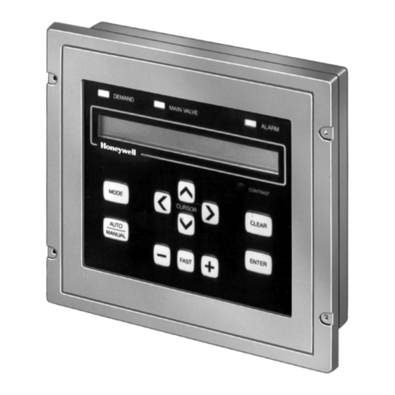
Keyboard and Display Module
Boiler Control System 7700
The Honeywell BCS 7700 is a microprocessor
based integrated control system for gas, oil, or
combination fuel single burner applications. The
BCS 7700 consists of a Chassis Module, Pro-
gram Module, Keyboard and Display Module,
Flame Amplifier, Solid State Sensors (Fuel Oil
and Water Temperature, Steam Pressure, Gas
Pressure, and Oil Pressure) and a Firing Rate
Motor. The BCS 7700 provides levels of safety,
functional capability and features beyond the
capacity of conventional controls. Functions of
the BCS 7700 include automatic burner sequenc-
ing, flame supervision, system status indication
and system diagnostics.
The Keyboard and Display Module is the pri-
mary user interface to the BCS 7700. The Key-
board and Display Module is used to configure
the system modules, adjust system operating pa-
rameters, and monitor system status.
2 row x 40 character Liquid Crystal Display.
3 Status LEDs.
T.M. • Rev. 9-91 • ©Honeywell Inc. 1991 • Printed in U.S.A. • Form Number 63-2287-1
Manual Firing Rate Control.
Alarm Silencing Switch.
CONTENTS
Specifications ................................................. 2
Ordering Information ..................................... 2
Installation ..................................................... 3
Checkout ......................................................... 8
ST7700
Advertisement

Related Manuals for Honeywell ST7700


Summary of Contents for Honeywell ST7700
- Page 1 Manual Firing Rate Control. 3 Status LEDs. Alarm Silencing Switch. CONTENTS Specifications ..........2 Ordering Information ........2 Installation ............. 3 Checkout ............8 T.M. • Rev. 9-91 • ©Honeywell Inc. 1991 • Printed in U.S.A. • Form Number 63-2287—1...
-
Page 2: Specifications
If you have additional questions, need further information, or would like to comment on our products or services, please write or phone: 1. Your local Honeywell Residential and Building Controls Division Sales Office (check white pages of your phone directory). - Page 3 ST7700 SPECIFICATIONS Fig. 2—BCS 7700 internal wiring diagram. (HOT) EARTH GROUND OIL SELECT 120 VAC GAS SELECT 11K1 OIL LINE PURGE VALVE LOAD ATOMIZING AIR ALARM DEMAND COMPRESSOR SIGNAL MOTOR STARTER WATER TEMP. 10K1 SENSOR / CON- DIGITAL COMMON FIG. ANALOG...
- Page 4 ST7700 SPECIFICATIONS Fig. 3—BCS 7700 field wiring diagram.
-
Page 5: Installation
ST7700 INSTALLATION Installation WHEN INSTALLING THIS PRODUCT… 1. Read these instructions carefully. Failure to follow Fig. 4—Keyboard and display module mount- them could damage the product. ing. 2. Refer to Fig. 2 and 3 for proper system wiring. 3. Installer must be a trained, experienced flame safe- guard technician. - Page 6 IN PROGRAM MODE 2. Cursor keys [</>]—The </> keys move the cursor BLC Program OperSetPoint 185 PSI around the ST7700 LCD fields. The cursor is the one [>] to set value [v] for next segment wide flashing horizontal line in the LCD.
- Page 7 ST7700 INSTALLATION Fig. 8—[Auto/Manual] key function. Fig. 9—[Enter] key function. IN "AUTO" AND OPERATE MODE Auto 190 PSI FlameSignal 2.5V IN OPERATE MODE 30% Rate OperSetPoint 185 PSI Auto 190 PSI FlameSignal 2.5V Standby GAS OperSetPoint 200 PSI PLACE SYSTEM IN MANUAL CONTROL,...
-
Page 8: Checkout
System Programming, refer to form 63-2290. M1117 Residential and Residential and Helping You Control Your World Building Controls Division Building Controls Division Honeywell Inc. Honeywell Limited—Honeywell Limitée 1985 Douglas Drive North 740 Ellesmere Road Golden Valley, MN 55422 Scarborough, Ontario QUALITY IS M1P 2V9...