Advertisement
Quick Links
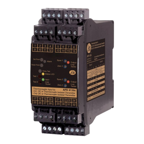
Thermocouple Input to Dual DC Output Splitter/Converter, Factory Ranged
1 Input:
Any Thermocouple
2 Outputs:
Two Independent Process Voltage or mA Signals, Alarm Relay Options
O Split or Convert a T/C Into 2 Independent DC Outputs
O Add Additional Isolated Output to Existing T/C
O Zero and Span Output Calibration
O Input LoopTracker
LED
®
O Sink/Source for DC Outputs
Applications
Q Split/Isolate T/Cs for PLC Input, Control or Validation
Q Interface Thermocouples with Panel Meters, PLCs,
Recorders, Data Acq., DCS, & SCADA Systems
Thermocouple Input, Factory Set
T/C types:
J, K, T, E, M, N, P, R, S, B, C, D, G
Temp. range: Full ANSI range, or specify °F or °C range
Linearity:
±0.1°C and 0.001°C resolution
Linearization: Polynomials, 1°C segments for types M and P
T/C CJC:
Automatic
T/C current: Less than 10 µA, including burnout sense
T/C burnout: Upscale (standard), B: downscale, N: none
Custom:
Provide T/C millivolt data, °F or °C range
Status LEDs
LoopTracker:
Variable brightness green for input level
Yellow LED:
Output Push-to-Test status, error status
Red/green LED: Alarm state (with alarm option only)
DC Output, Channel 1, Factory Set
Linearized to temperature
Voltage:
0-1 V to 0-10 V (10 mA max.), ±1 V to ±10 V
Current:
0-1 mA to 0-20 mA
20 V compliance, 1000 Ω at 20 mA
Sinking or sourcing output
Loop power: 20 VDC nom., regulated, 25 mADC
<10 mV
max. ripple
RMS
DC Output, Channel 2, Factory Set
Linearized to temperature
Voltage:
0-1 V to 0-10 V (10 mA max.), ±1 V to ±10 V
Current:
0-1 mA to 0-20 mA
20 V compliance, 1000 Ω at 20 mA
Sinking or sourcing output
Loop power: 20 VDC nom., regulated, 25 mADC
<10 mV
max. ripple
RMS
Output Calibration
Zero and span potentiometers for each output, ±15% range
Output Push-to-Test (Output 1 & Output 2)
Front push buttons and terminals enable/disable test level out-
puts. Each set to 75% of output span. Specify custom setting.
Output Resolution
16 bit
Output Ripple and Noise
Less than ±0.2% of span
Optional Alarm Relay
Single setpoint dual DPST contact sets, factory configured
1 Form A (NO) and 1 Form B (NC) contact sets (4 terminals)
May be field wired for Form C operation
8 A max @ 240 VAC
AC inductive load
(cos f = 0.4)
resistive load
8
Use external contact
5
protection (RC snub-
3
ber) for inductive loads
DC inductive load
1
(L/R = 7 ms)
Red/Green bi-color
LED indicates alarm
0.5
DC resistive
0.3
status
load
One set point, 12
0.1
0
3 5 10
turn potentiometer,
Switching Voltage (V)
0-100% of span
One reset point, 12 turn potentiometer, 0-100% of span
Default: HI alarm, non-latching, normal acting (failsafe)
Relay Test button toggles relay to opposite state or resets
relay with HT option
Ambient Temperature Range and Stability
–10°C to +60°C operating ambient
Better than ±0.02% of span per °C stability
Response Time
500 milliseconds minimum
Isolation
A
A
P
P
BSOLUTE
BSOLUTE
ROCESS
ROCESS
H H H H H H
H H H H H
H H H H H H
H H H H H
H H H H H H
H H H H H
H H H H H H
H H H H H
H H H H H H
Made in USA
Applications Link
api-usa.com/apps
Free Factory
I/O Setup!
Full 4-way galvanic: input, output 1, output 2,
power, 1200 V
RMS
600 VACp or 600 VDC common mode protection
75 dB minimum common mode rejection
Simultaneous 50 Hz and 60 Hz rejection
Housing and Connectors
IP 40, requires vertical installation on a 35 mm DIN
rail inside a panel or enclosure. Allow room for
air flow. For use in Pollution Degree 2 Environment.
Eight 4-terminal removable connectors,
14 AWG max. wire size
Power
85-265 VAC, 50/60 Hz or 60-300 VDC, 3 W maximum
D versions: 9-30 VDC or 10-32 VAC 50/60 Hz, 3 W maximum
Dimensions
1.78" W x 4.62" H x 4.81" D
(45 mm W x 117 mm H x 122 mm D)
Description
The APD 41393 accepts a thermocouple temperature input and
provides two independent DC process outputs. This makes it
useful to split, isolate, and transmit a thermocouple signal for
measurement, data recording, or validation.
The thermocouple input type and temperature range are fac-
tory set. The two DC output types and ranges are factory set.
The DC outputs can be different and both correspond to the
input temperature range specified. Use appropriate thermo-
couple extension wire for the input as needed.
The input is sampled, CJC compensated, digitally converted to
a linearized temperature signal, and then passed to the output
stages where it is converted to the two DC outputs.
AC resistive
Output Sink/Source Versatility
load
The APD 41393 includes a 20 VDC loop excitation supply for
any channel ordered with a mA output. A mA output can be
selectively wired for sinking or sourcing allowing use with a
powered or unpowered milliamp device.
How to Order—Factory Ranged and Configured
Model
30 50 100 300 500
APD 41393
APD 41393 D
APD 41393 H
APD 41393 DH
APD 41393 L
APD 41393 DL
I
I
NSTRUMENTS
NSTRUMENTS
Output Test for
DC Channels
9 10 11 12
Sink or Source
Output for
mADC Channels
Optional Alarm
Relay
Zero and
Span for
Each Output
Status LED
Input
LoopTracker
LED
Pb
Lead
Free
Universal Power
min.
17 18 19 20
Power
Input
85-265 VAC, 60-300 VDC
9-30 VDC, 10-32 VAC
Specify
85-265 VAC, 60-300 VDC
T/C type,
temperature
range in
9-30 VDC, 10-32 VAC
°F or °C
85-265 VAC, 60-300 VDC
9-30 VDC, 10-32 VAC
1220 American Way Libertyville, IL 60048
Phone:
800-942-0315
APD 41393
Quick Link:
1
2
3
4
5
6
7
8
13 14 15 16
21 22 23 24
25 26 27 28
29 30 31 32
Full 4-way galvanic isolation (input, output 1, output 2, power)
make this module useful for ground loop elimination, common
mode signal rejection, and noise pickup reduction.
LoopTrackers
An API exclusive feature includes a green LoopTracker LED
that varies in intensity with changes in the input signal and
red LoopTracker LEDs that vary in intensity with changes in
the DC output signals. It provides a quick visual picture of your
process at all times and can greatly aid in saving time during
initial startup and troubleshooting.
Output Push-to-Test
An API exclusive feature includes output test switches for each
DC output to provide a fixed output (independent of the input)
when pressed. The output test greatly aids in saving time dur-
ing initial startup and/or troubleshooting.
The output test level is factory set to approximately 75% of
span but a custom test level may be ordered.
Outputs
Alarm
Code
-
Upscale burnout (standard)
Ch. 1 specify
B
Downscale burnout
VDC or mADC
none
N
No burnout, last valid value
range
Custom
RA
Reverse-acting alarm
Push-to-Test
___% span
HI alarm
HP
Latching relay, power-off reset
(failsafe std.)
Ch. 2 specify
HT
Latching relay, push button reset
VDC or mADC
U
range
Conformal coating for moisture
resistance
Custom
LO alarm
Push-to-Test
(failsafe std.)
___% span
api-usa.com
Fax: 800-949-7502
api-usa.com/tc
Removable Plugs
See Wiring
Diagrams on
Next Page
Options
Description
© 02-20
Advertisement

Related Manuals for Absolute Process Instruments APD 41393


Summary of Contents for Absolute Process Instruments APD 41393
- Page 1 The output test greatly aids in saving time dur- The APD 41393 includes a 20 VDC loop excitation supply for Use external contact ing initial startup and/or troubleshooting. any channel ordered with a mA output. A mA output can be...
- Page 2 Instructions APD 41393 Optional Precautions Optional Alarm Relay * Do not make alarm WARNING! All wiring must be performed by a qualified electrician or See model/serial number label for the factory configured relay connections to Output 1 Output 1 contacts instrumentation engineer.